

Bosch GLL 150 E, LR 3 Operating/safety Instructions Manual
IMPORTANT: IMPORTANT : IMPORTANTE:
Read Before Using Lire avant usage Leer antes de usar
Operating/Safety Instructions
Consignes de fonctionnement/sécurité
Instrucciones de funcionamiento y seguridad
For English Version Version française Versión en español
See page 6 Voir page 17 Ver la página 31
1-877-BOSCH99 (1-877-267-2499) www.boschtools.com
Call Toll Free for
Consumer Information
& Service Locations
Pour obtenir des informations
et les adresses de nos centres
de service après-vente, appelez
ce numéro gratuit
Llame gratis para
obtener información
para el consumidor y
ubicaciones de servicio
GLL 150 E
LR 3
-2-
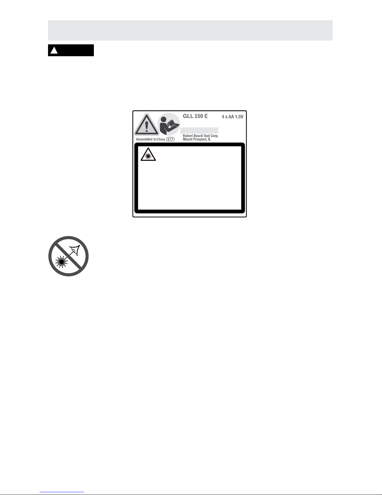
3 601 K63 K80
IEC 60825-1:2007-03
max output <1 mW @ 640 nm
2
Laser Radiation. Do not stare into the beam. Class 2 laser
product. Complies with 21 CFR 1040.10 and 1040.11 except
for deviations pursuant to Laser Notice 50, 6/24/2007
8
7
1
1
2
3
4
6
5
-3-
ED
A
C
B
-4-
F
G
12
10
11
9
14
F
G
13
-5-
Read all instructions. Failure to follow all instructions listed below may result
in hazardous radiation exposure, electric shock, fire and/or serious injury. The
term “tool” in all of the warnings listed below refers to your mains-operated (corded) tool or batteryoperated (cordless) tool.
The following labels are on your laser tool for your convenience and safety. They indicate
where the laser light is emitted by the tool. ALWAYS BE AWARE of their location when
using the tool.
DO NOT direct the laser beam at persons or animals and do not stare into the
laser beam yourself. This tool produces laser class 2 laser radiation and complies
with 21 CFR 1040.10 and 1040.11 except for deviations pursuant to Laser Notice
No. 50, dated June 24, 2007. This can lead to persons being blinded.
DO NOT remove or deface any warning or caution labels. Removing labels
increases the risk of exposure to laser radiation.
Use of controls or adjustments or performance of procedures other than those specified in
this manual, may result in hazardous radiation exposure.
ALWAYS make sure that any bystanders in the vicinity of use are made aware of the
dangers of looking directly into the laser tool.
DO NOT place the laser tool in a position that may cause anyone to stare into the laser
beam intentionally or unintentionally. Serious eye injury could result.
ALWAYS position the laser tool securely. Damage to the laser tool and/or serious injury to the
user could result if the laser tool falls.
ALWAYS use only the accessories that are recommended by the manufacturer of your
laser tool. Use of accessories that have been designed for use with other laser tools could result in
serious injury or unsatisfactory performance.
DO NOT use this laser tool for any purpose other than those outlined in this manual. This
could result in serious injury or unsatisfactory performance.
DO NOT leave the laser tool “ON” unattended in any operating mode.
DO NOT disassemble the laser tool. There are no user serviceable parts inside. Do not
modify the product in any way. Modifying the laser tool may result in hazardous laser radiation
exposure.
SAVE THESE INSTRUCTIONS
General Safety Rules
Radiación Láser. No mire al rayo. Producto láser de Clase
2. Cumple con las normas 21 CFR 1040.10 y 1040.11,
excepto por las desviaciones conforme al Aviso para
láseres 50 del 24 de juio de 2007.
Rayonement laser. Ne regardez pas directement dans le
faisceau. Produit laser de Classe 2. Conforme à 21 CFR
1040.10 et 1040.11, sauf pour les écarts suivant l’Avis laser
50, 24/6/2007.
3 601 K63 K80
IEC 60825-1:2007-03
max output <1 mW @ 640 nm
2
Laser Radiation. Do not stare into the beam. Class 2 laser
product. Complies with 21 CFR 1040.10 and 1040.11 except
for deviations pursuant to Laser Notice 50, 6/24/2007
!
WARNING

-6-
Work area safety
Keep work area clean and well lit. Cluttered
or dark areas invite accidents.
DO NOT operate the laser tool around
children or allow children to operate the
laser tool. Serious eye injury could result.
DO NOT use measuring tools, attachments
and accessories outdoors when lightening
conditions are present.
Electrical safety
Batteries can explode or leak, cause injury
or fire. To reduce this risk, always follow all
instructions and warnings on the battery
label and package.
Remove the batteries from the tool when not
using it for extended periods. When storing
for extended periods, the batteries can corrode
and discharge themselves.
DO NOT short any battery terminals.
DO NOT charge alkaline batteries.
DO NOT mix old and new batteries.
Replace all old batteries at the same time
with new batteries of the same brand and
type.
DO NOT mix battery chemistries.
Dispose of or recycle batteries per
local code.
DO NOT dispose of batteries in fire.
Keep batteries out of reach of children.
Personal safety
Stay alert, watch what you are doing and
use common sense when operating a tool.
Do not use a tool while you are tired or
under the influence of drugs, alcohol or
medication. A moment of inattention while
operating a tool may result in serious personal
injury or incorrect measurement results.
Use safety equipment. Always wear eye
protection. Safety equipment such as dust
mask, non-skid safety shoes, hard hat, or
hearing protection used for appropriate
conditions will reduce personal injuries.
DO NOT use the laser viewing glasses as
safety goggles. The laser viewing glasses
are used for improved visualization of the laser
beam, but they do not protect against laser
radiation.
DO NOT use the laser viewing glasses as
sun glasses or in traffic. The laser viewing
glasses do not afford complete UV protection
and reduce color perception.
DO NOT use any optical tools such as, but
not limited to, telescopes or transits to view
the laser beam. Serious eye injury could result.
DO NOT stare directly at the laser beam or
project the laser beam directly into the eyes
of others. Serious eye injury could result.
Use caution when using measuring tools in
the vicinity of electrical hazards.
Magnets
Keep the tool and laser
target away from cardiac
pacemakers. The magnets of
the tool and laser target plate
generate a field that can impair
the function of cardiac
pacemakers.
Keep the tool and laser target away from
magnetic data medium and magneticallysensitive equipment.
The effect of the magnets of the tool and laser
target plate can lead to irreversible data loss.
Noise Information
Do not hold the measuring tool close to
your ear! Do not hold the measuring tool
closer than 1 meter from your ear when
using loud volume! The A-weighted sound
pressure level of the audio signal at one meter
distance is 75-85dB(A). Serious injury could
result.
Use and care
Use the correct tool for your application. The
correct tool will do the job better and safer.
Do not use the tool if the switch does not
turn it on and off. Any tool that cannot be
controlled with the switch is dangerous and
must be repaired.
Store idle tool out of the reach of children
and do not allow persons unfamiliar with the
tool or these instructions to operate the tool.
Tools are dangerous in the hands of untrained
users.
Maintain tools. Check for misalignment or
binding of moving parts, breakage of parts
and any other condition that may affect the
operation. If damaged, repair tool before
use. Many accidents are caused by poorly
maintained tools.
Use the tool, accessories, etc., in
accordance with these instructions and in
the manner intended for the particular type

-7-
The numbering of the product features shown
refers to the illustration of the tool on the graphic
page.
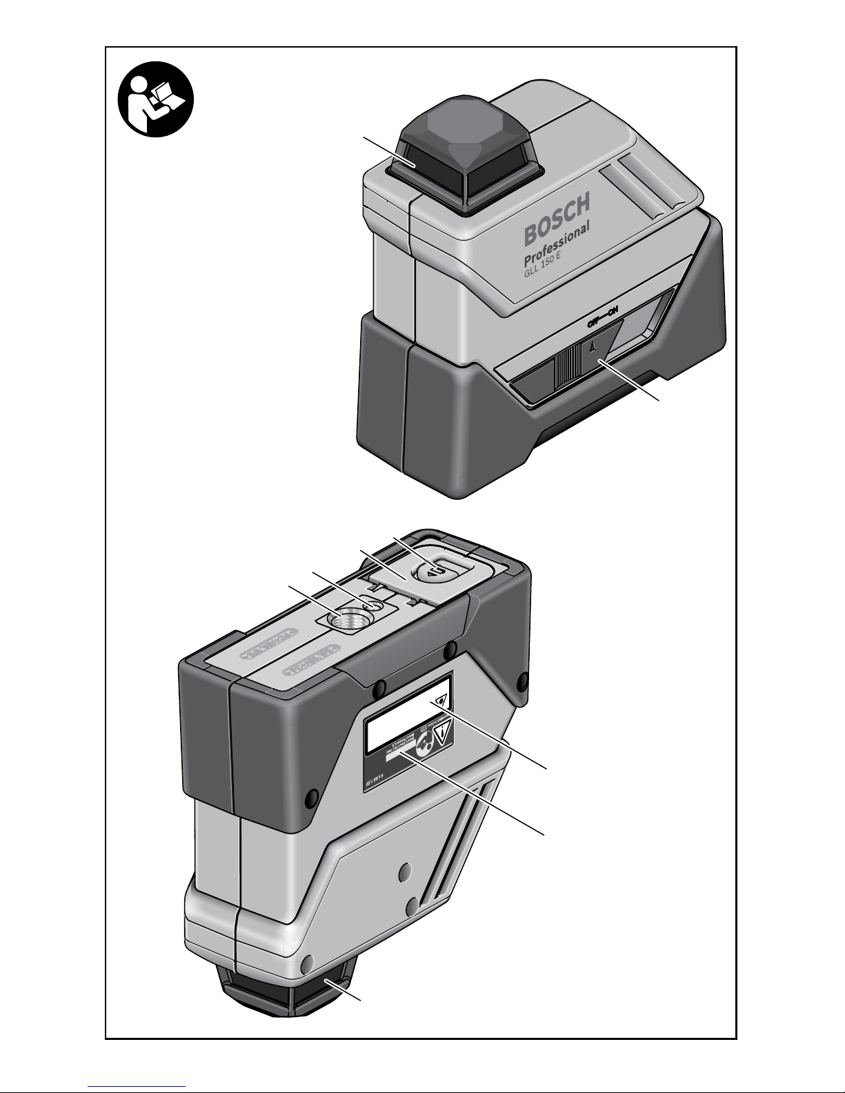
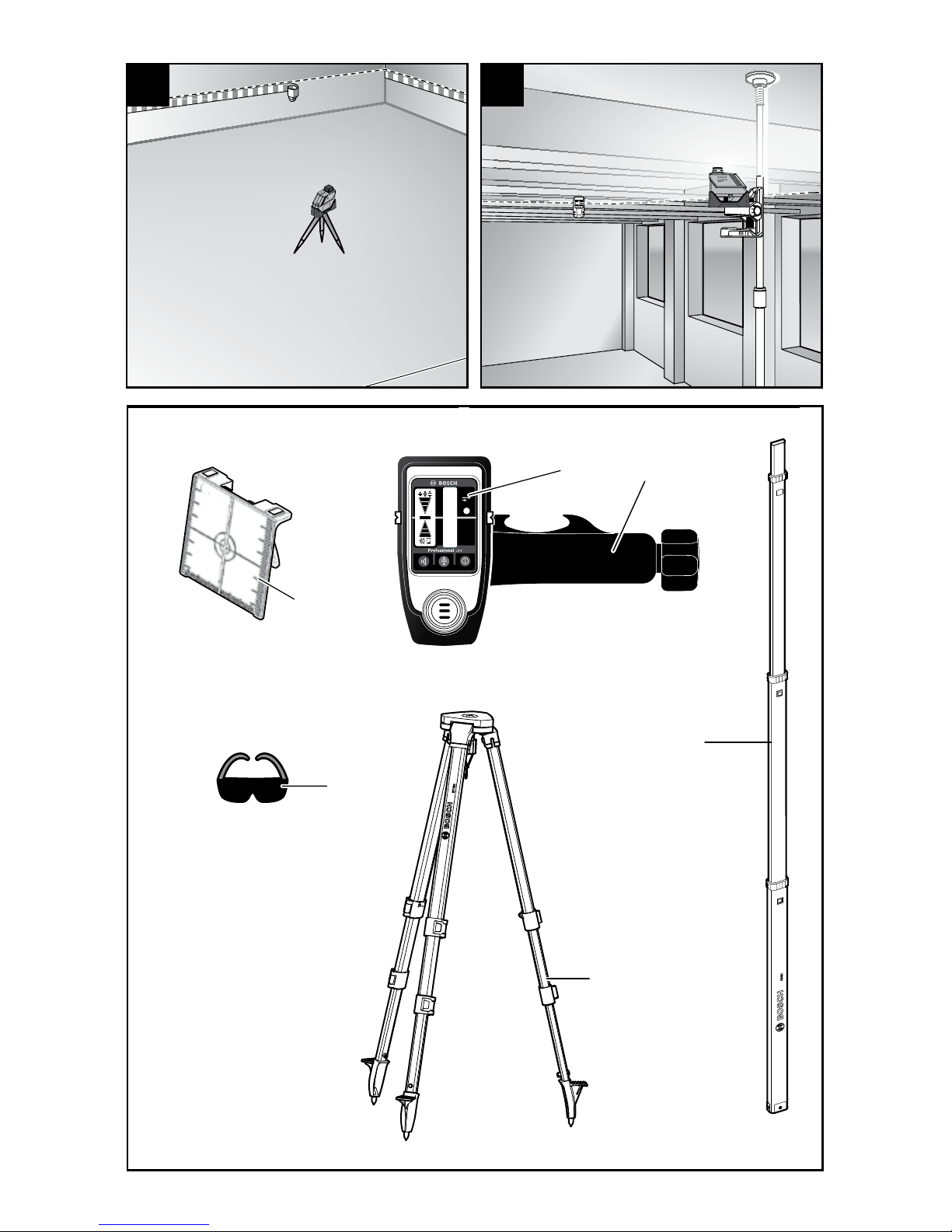
1 Exit opening for laser beam
2 On/Off switch
3 Tripod mount 5/8”-11
4 Tripod mount 1/4”-20
5 Latch of battery lid
6 Battery lid
7 Laser warning label
8 Serial number
9 Laser target plate*
10 Laser receiver (LR 3)
11 Rod clamp
12 Laser viewing glasses*
13 Tripod (BT 152)
14 Leveling rod (GR 8 C)
* The accessories illustrated or described are
not included as standard delivery.
Inserting/Replacing the Battery
Always replace all batteries
at the same time. Only
use batteries from one brand and with the
identical capacity.
Remove the batteries from the tool when not
using it for extended periods. When storing
for extended periods, the batteries can corrode
and discharge themselves.
Alkaline batteries are recommended for
the tool.
To open the battery compartment 6, slide the
latch 5 in the direction of the arrow and fold the
battery lid up. Insert the batteries.
When inserting, pay attention to the correct
polarity according to the representation on the
inside of the battery lid.
At approximately 6 hours battery life remaining,
the unit will indicate "battery weak" status by
rapidly flashing the laser on and off for 30
seconds. It will then resume normal operation
until complete switch-off. The 30-second
flashing will repeat on initial startup.
Intended Use
Preparation
Features
The tool is intended for determining and checking level.
!
WARNING
of tool, taking into account the working
conditions and the work to be performed.
Use of the tool for operations different from
those intended could result in a hazardous
situation.
Service
Have your tool serviced by a qualified repair
person using only identical replacement
parts. This will ensure that the safety of the tool
is maintained.
Develop a periodic maintenance schedule
for tool.
Follow checking recalibration procedures
outlined in this instruction manual.
When cleaning a tool be careful not to
disassemble any portion of the tool since
internal wires may be misplaced or pinched
or may be improperly mounted. Certain
cleaning agents such as gasoline, carbon
tetrachloride, ammonia, etc. may damage
plastic parts. agents such as gasoline, carbon
tetrachloride, ammonia, etc. may damage
plastic parts.
SAVE THESE INSTRUCTIONS.

-8-
Standard Range Mode
- Range Radius X-Axis 3 ft to 196 ft (1 m to 60 m)
- Range Radius Y-Axis 3 ft to 65 ft (1 m to 20 m)
Long Range Mode
- Range Radius X-Axis 66 ft to 260 ft (20 m to 80 m)
- Range Radius Y-Axis 66 ft to 260 ft (20 m to 80 m)
Self Leveling Range
(typically)
± 4 degrees
Out of Level Warning Slow flashing of the laser for 30 secs
Pendulum Transport Lock Yes
Low Battery Warning At approximately 6 hours battery life remaining:
Flashing Laser – (ON 0.2 secs and OFF 0.2 secs for a
30-second period then ON until battery is exhausted,
repeats on initial startup)
Mounting Threads 1/4-20 and 5/8-11
Auto Shut-off 15 min. if not level, none if level
IP Rating IP55
Battery Type 4 x AA cell Alkaline
Battery Life 50 hours
Safety Class 2
Laser Diode 640 nm
Operating Temperature 14° F to 122° F (-10° C to 50° C)
Level Accuracy ± 3/16 in @ 100 ft (± 4.5 mm @ 30 m)
Accessories Laser Detector w/bracket, Case
The working range can be decreased by unfavorable environmental conditions (e.g. direct sun
irradiation).
Technical Data

-9-
Initial Operation
An accuracy check should always be carried
out before use.
Protect the tool against
moisture and direct
sun light.
Do not subject the tool to extreme
temperatures or variations in temperature.
As an example, do not leave it in vehicles for
longer periods. In case of large variations in
temperature, allow the tool to adjust to the
ambient temperature before putting it into
operation. In case of extreme temperatures or
variations in temperature, the accuracy of the
tool can be impaired.
Avoid heavy impact or dropping of the
tool. After heavy exterior impact on the tool,
an accuracy check should always be carried
out before continuing to work (see “Leveling
Accuracy”).
Switch the tool off during transport. When
switching off, the leveling unit, which can be
damaged in case of intense movement, is
locked.
Switching On and Off
To switch on the tool, slide the On/Off switch 2
to the “on”. position. Immediately after switching
on, the tool sends laser beams out of the exit
opening 1.
Align arrow of ON-OFF
switch directly below
ON position. If ON -OFF switch is not fully
engaged, self-leveling feature is not activated
and laser line will be out of level.
To switch off the tool, slide the On/Off switch
2 to the “off” position. When switching off, the
leveling unit is locked.
Do not point the laser beam
at persons or animals and
do not look into the laser beam yourself, not
even from a large distance.
Do not leave the switched on tool
unattended and switch the tool off after use.
Operating Modes
The tool has two operating mode:
- Horizontal operation: generates a self-
leveled, horizontal plane that's pulsed. The
LR 3 laser receiver can be used.
- Slope operation: generates a sloped
plane for indoor work at an angle. Pulse
is deactivated and the LR 3 laser receiver
cannot be use
Pulse Function
To work with the laser receiver 10, the pulse
function is activated when using the tool in
horizontal operation.
With the pulse function, the laser lines flash
at very high frequency and thus become
detectable by the laser receiver 10.
Automatic Leveling
Working with Automatic Leveling
Position the tool on a level and firm support,
such as the BT 152 tripod 13.
Push the On/Off switch 2 to the “on” position.
After switching on, the leveling function
automatically compensates irregularities within
the self-leveling range of ±4°. The leveling is
finished as soon as the laser beams do not
move any more.
If automatic leveling is not possible, e.g.
because the surface on which the tool stands
deviates by more than 4° from the horizontal
plane, the laser lines begin to flash.
Set up the tool in level position and wait for the
self-leveling to take place. As soon as the tool
is within the self-leveling range of ±4°, the laser
beam lights up continuously.
In case of ground vibrations or position changes
during operation, the tool is automatically
re-leveled. To avoid errors, check the position
of the horizontal laser line with regard to the
reference point upon releveling.
Working without Automatic
Leveling
Tilt the unit so the line is projected at the angle
you need it. The laser will flash for the first 30 s
until it turns into a solid line.
Working Advice
Always use the center of
the laser beam for marking.
The thickness of the laser line changes with the
distance.
Operation
!
WARNING
!
CAUTION
!
CAUTION
!
WARNING
-10-
Working with the laser target plate
The laser target plate 9 increases the visibility
of the laser beam under unfavourable
conditions and at large distances.
The reflective part of the laser target plate 9
improves the visibility of the laser line. Due to
transparency, the laser line is also visible from
the back side of the laser target plate.
Working with the Tripod
A tripod offers a stable, height-adjustable
measuring support. Position the tool with either
the 1/4-20 tripod mount 4 onto the thread of
a commercially available camera tripod or the
preferred method is to mount to a construction
tripod, use the 5/8-11 tripod mount 3. Tighten
the tool with the tripod mounting stud.
Laser Viewing Glasses (Optional
Accessory)
The laser viewing glasses filter out the ambient
light. This makes the red light of the laser
appear brighter for the eyes.
Do not use the laser
viewing glasses as safety
goggles. The laser viewing glasses are used
for improved visualization of the laser beam, but
they do not protect against laser radiation.
Do not use the laser viewing glasses as sun
glasses or in traffic. The laser viewing glasses
do not afford complete UV protection and
reduce color perception.
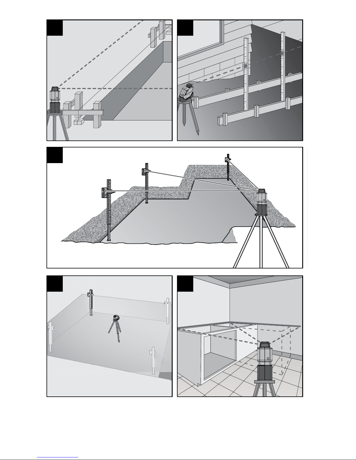
Work Examples (see figures A–G)
Applicational examples for the tool can be
found on the graphics pages.
Use with Attachments
!
WARNING
Influences on Accuracy
The ambient temperature has the greatest
influence. Especially temperature differences
occurring from the ground upward can divert
the laser beam.
Because the largest difference in temperature
layers is close to the ground, the tool should
always be mounted on a tripod when working
at distances exceeding 65 ft (20 m). If possible,
also set up the tool in the center of the work
area.
Apart from exterior influences, device-specific
influences (such as heavy impact or falling
down) can lead to deviations. Therefore, check
the accuracy of the tool each time before
starting your work.
Should the tool exceed the maximum deviation
during one of the tests, please have it repaired
by a Bosch after-sales service center.
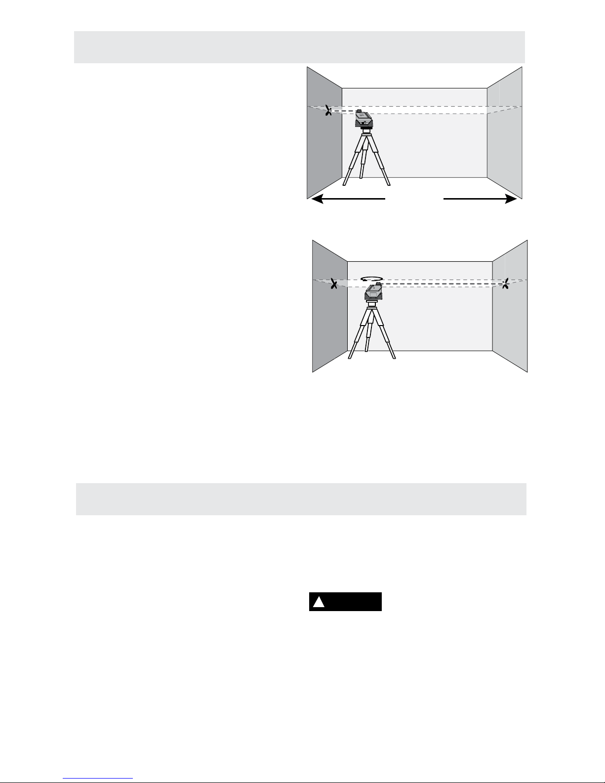
Checking the Horizontal Leveling Accuracy.
A free measuring distance of 16 ft (5 m)on a
firm surface in front of two walls A and B is
required for the check.
– Mount the tool onto a tripod, or place it on
a firm and level surface close to the wall A.
Switch the tool on.
– Direct the laser against the close wall A and
allow the tool to level in. Mark a point on
both walls where the laser indicates (point
y). Mark the center of the laser beam on the
wall (at point y and point z).
– Turn the tool around by 180°, allow it to level
in. The laser line should indicate the same
point within product specification tolerances.
Leveling Accuracy
AB
AB
y
180˚
y
z
16 ft (5m)
AB
y
16 ft (5m)
-11-
LR 3 Laser Line Detector
1
6
2
3
10
7
8
5
4
9
Fig. 1
3
10
7
8
5
4
14
11
12
15
9
16
13
1
1
2
4
3
3
Fig. 2 Fig. 6
Fig. 3 Fig. 4 Fig. 5

-12-
– To attach the rod clamp (fig. 6 #1) to the
detector, align projections on the rod clamp
with corresponding recess on the back of
the detector, and tighten the knob (fig. 6
#2). To detach rod clamp (fig. 6 #1) from
the detector, unscrew the knob (fig. 6 #2)
completely.
– To attach the rod clamp (fig. 6 #1) to
leveling rod 14, loosen the knob (fig. 6 #3)
on the rod clamp (fig. 6 #1), slide the rod
clamp on the leveling rod 14 to the desired
location, and tighten the knob (fig. 6 #3).
The spirit level (fig. 6 #4) can be used to
approximately level the leveling rod. Adjust
the position of the leveling rod until the
bubble in the spirit level (fig. 6 #4) is within
the circle.
Wear eye protection. If the
spirit level leaks, soak up
with appropriate absorbent material and
dispose of safely. The spirit level contains
flammable liquid that may cause respiratory
tract, eye and skin irritation.
– Turn on the instrument by pressing the
ON/OFF button on the keypad. The LCD
symbols will momentarily be lit and the
unit will beep once. The Coarse bandwidth
indicator and soft volume indicator will
remain lit.
– Expose the beam capture window of the
laser detector towards the direction of the
pulsed laser line.
– Slowly move the laser detector in an upward
and downward direction until the LCD beam
indicator arrows appear and/or a pulsing
audio signal is heard. Use the Bandwidth
Resolution Selection feature to choose
between the Fine/Coarse setting. Coarse
resolution setting is for approximating level
or for initial locating of the center level point.
Fine resolution setting is used for most
accurate pin pointing of level.
– Move the detector upward when the bottom
arrow icon is lit (fig. 5) (with volume on, a
slow pulsing audio tone is heard). Move the
detector downward when the top arrow icon
The numbering of the product features shown
refers to the illustration of the tool on the graphic
page 11 (Fig. 1).
1 LCD readout window
2 Speaker
3 Beam capture window
4 Bandwidth Resolution Selection
5 Power ON/OFF
6 Volume OFF/SOFT/LOUD
7 Rear LCD readout window
8 Battery door
9 Range Extender Indicator LED
10 Range Extender Feature Button
LCD Display (Fig. 2)
11 Top Arrow
12 Bottom Arrow
13 Speaker Volume
14 Bandwidth Resolution Indicators
15 Level Beam
16 Low Battery Indicator
Power
Two AA batteries will provide up to 30 hours of
continuous use. When the instrument is turned
on and the low battery symbol remains lit, the
battery should be replaced.
Installing and Removing Batteries
To replace batteries, detach the rod clamp (fig.
6 #1) from the detector by turning the knob (fig.
6 #2) on the rod clamp. Open the battery door
(fig. 1 #8) by pulling latch.
Install batteries with correct polarity as indicated
in the battery compartment. Close the battery
door and engage the latch.
The Bosch Electronic Laser Line Detector aids in locating and targeting a visible or invisible beam
emitted by a Pulsed Line laser; perfect for use in outdoor conditions, where sunlight and distance
may make locating the beam more difficult. The laser detector includes a rod clamp which allows to
mount the detector onto square, round or oval leveling rods.
Introduction
LR 3 Features
LR 3 Operation
!
WARNING
-13-
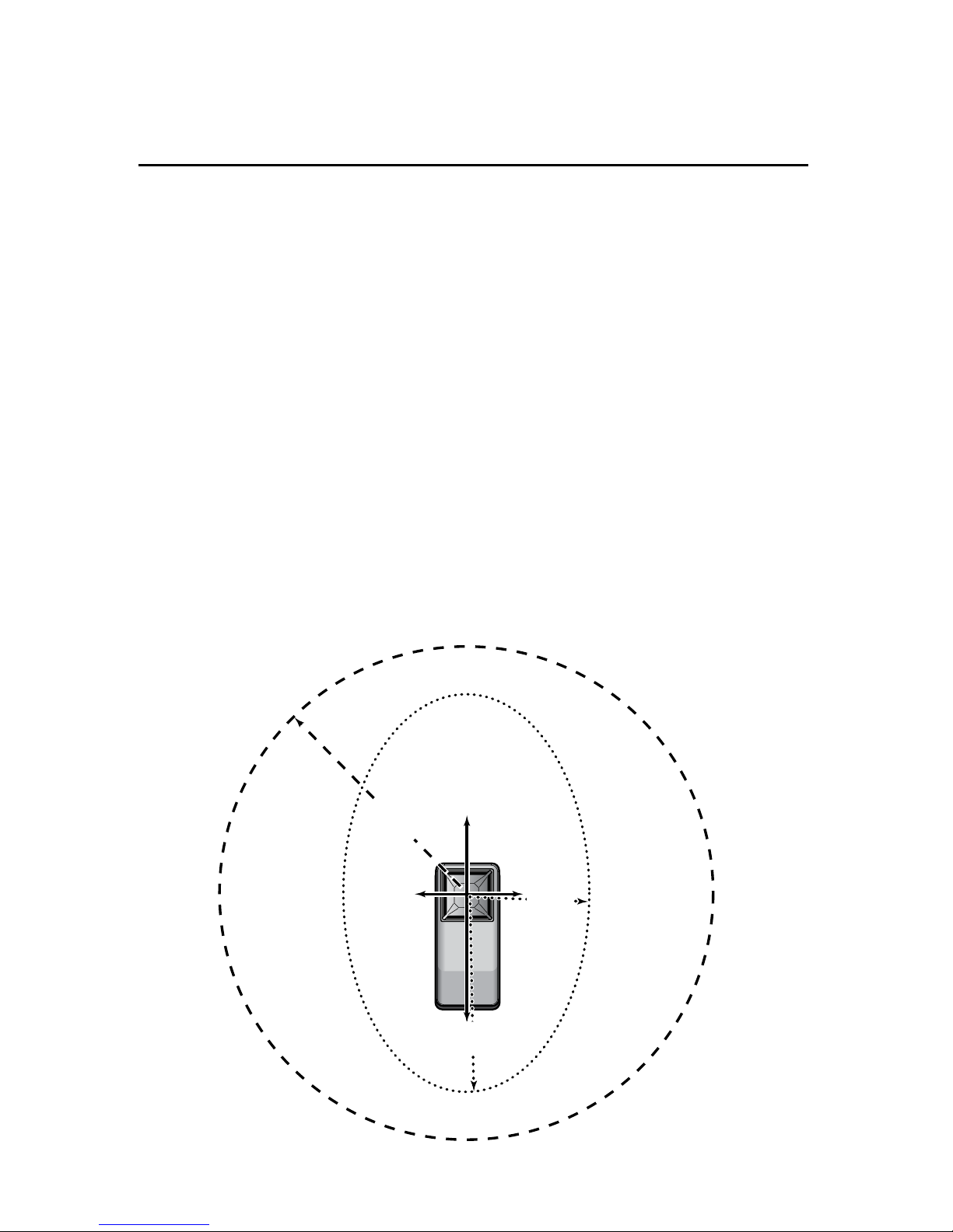
The design of the LR 3 detector is an innovation
to the market. The detector can be switched
between standard and long range modes
enabling extended distance capabilities for the
GLL 150 E and reducing the issue with “scatter”
associated with close in use of line lasers.
When used with the GLL 150 E exterior laser,
the LR 3 receiver enables the instrument to be
used in a work area up to 530 feet (160 m) in
diameter. In standard mode the GLL 150 E and
LR 3 combination will have the elliptical pattern
typical of cone lasers with a maximum range
radius of 196 feet (60 m) along the X-axis and
a minimum range raduis of 65 feet (20 m) along
the Y-axis. Long range mode enables a 265
feet (80 m) circular radius working area.
The area designated by the DASHED circle is
the work area in LONG RANGE MODE.
The area designated by the DOTTED ellipsoid
is the work area in STANDARD RANGE
MODE.
Extended Range Function
The LR 3 receiver defaults to and should be
used in its standard operating mode for most
leveling projects. If the operator is having
difficulty receiving a reading at extended
distances (greater than 65 ft or 20 meters),
indicated by difficulty in locating the center bar
then the extended range button (fig. 1 #10) on
the detector can be pressed and the LED will
be illuminated (fig. 1 #9).
Close Proximity Use
When using the LR 3 in close proximity to the
laser (3ft to 15ft) care must be taken due to the
high sensitivity of the LR 3 and the scatter from
the cone, glass, dust on glass, and surrounding
objects. Close proximity detection should be
validated against reflections and scatter by
ensuring that both the directional arrows are on
either side of the center bar (see fig 3 thru 5).
This can be done by moving the LR 3 up and
down relative to the center bar to locate the
arrows. Do not use the detector closer than 3 ft
from the laser.
X-Axis
Y-Axis
265 ft
(80 m)
65 ft
(20 m)
196 ft
(60 m)
is lit (fig. 3)(with volume on, a slightly faster
audio tone is heard). When the line is level,
the level laser line indicator will be lit (fig. 4)
(with volume on, a rapid audio tone will be
heard).
If the detector is not struck by a laser beam
after 5 minutes, the detector will automatically
shut itself off to preserve battery life. Turn the
instrument back on using the power button.

-14-
Note: Sensitivity values based on standard conditions with GLL 150 E.
LR 3 Technical Data
Range
In standard range mode
In long range mode
3 to 590 ft (1 to 180 m maximum) dependent on laser
source, laser orientation and selected LR 3 range.
the minimum operating distance is 3 ft (1m),
the maximum operating distance is:
- up to 196 ft (60 m) to GLL 150 E in 0 & 180 degree
orientations (X-Axis)
- up to 65 ft (20 m) to GLL 150 E in 90 & 270 degree
orientations (Y-Axis)
the minimum operating distance is 65 ft (20 m),
the maximum operating distance is
265 ft (80 m) to GLL 150 E in all orientations
The LR 3 powers on in standard range mode.
Accuracy
Fine = ± 1/16” (1.5mm) selectable
Coarse = ± 1/8” (3.0mm) selectable
Fine and Coarse modes are switch pad selectable.
This instrument is gasket sealed for water and dust protection. Use a soft, dry cloth to remove any
dirt or moisture from the instrument before storage. Do not use benzene, paint thinner, or other
solvents to clean the instrument. Remove battery before long-term storage of the instrument.
Care of Your Laser Detector
LR 3 Special Features
The laser detectors have built in electronic
filtering for bright sunlight and electromagnetic
interference. Three distinct audio patterns
(high, on-grade, and low) assist targeting from
a distance.
The detector LR 3 has three speaker selections
(Off, Soft (~75 dB) and Loud (~85 dB)),
measured at 3 ft (1 meter).
Audio Volume Control
Pressing the volume button (fig. 1 #6) causes
the unit to cycle through volume off, soft
volume, loud volume. After each press, the
speaker will beep once to acknowledge the
button press and demonstrate the volume level.
When the volume is off or soft selected, there
will be one short beep. When the volume is
loud, there will be a loud beep.
 Loading...