

Installation and
service instructions
Room controller
Logamatic EMS
6 720 618 477-00.1RS
Programming unit RC35
6 720 801 387 (2011/05) GB

Table of contents
Logamatic EMS – 6 720 801 387 (2011/05)
2
Table of contents
Guide to instructions . . . . . . . . . . . . . . . . . . . . . . . . . . . . . . . . . . . . . . . . . . . . . . . . . . . . . . . 4
1 Key to symbols and safety instructions . . . . . . . . . . . . . . . . . . . . . . . . . . . . . . . . . . . . . . . 5
1.1 Explanation of symbols . . . . . . . . . . . . . . . . . . . . . . . . . . . . . . . . . . . . . . . . . . . . . . . . . . . . . 5
1.2 Safety instructions . . . . . . . . . . . . . . . . . . . . . . . . . . . . . . . . . . . . . . . . . . . . . . . . . . . . . . . . 6
2 Product information . . . . . . . . . . . . . . . . . . . . . . . . . . . . . . . . . . . . . . . . . . . . . . . . . . . . . . . . 7
2.1 Correct use . . . . . . . . . . . . . . . . . . . . . . . . . . . . . . . . . . . . . . . . . . . . . . . . . . . . . . . . . . . . . . 7
2.2 EU Declaration of Conformity . . . . . . . . . . . . . . . . . . . . . . . . . . . . . . . . . . . . . . . . . . . . . . . 7
2.3 Included in Delivery . . . . . . . . . . . . . . . . . . . . . . . . . . . . . . . . . . . . . . . . . . . . . . . . . . . . . . . 7
2.4 Specification . . . . . . . . . . . . . . . . . . . . . . . . . . . . . . . . . . . . . . . . . . . . . . . . . . . . . . . . . . . . . 8
2.5 Validity of these instructions for function modules (accessories) . . . . . . . . . . . . . . . . . . 9
2.6 Accessories . . . . . . . . . . . . . . . . . . . . . . . . . . . . . . . . . . . . . . . . . . . . . . . . . . . . . . . . . . . . . . 9
2.7 Replacement of ERC with RC35 . . . . . . . . . . . . . . . . . . . . . . . . . . . . . . . . . . . . . . . . . . . 10
3 Installation . . . . . . . . . . . . . . . . . . . . . . . . . . . . . . . . . . . . . . . . . . . . . . . . . . . . . . . . . . . . . . . 11
3.1 Choosing the right installation position . . . . . . . . . . . . . . . . . . . . . . . . . . . . . . . . . . . . . . 11
3.1.1 Installation in the reference room . . . . . . . . . . . . . . . . . . . . . . . . . . . . . . . . . . . . . . . . . . . 11
3.1.2 Installation on boiler . . . . . . . . . . . . . . . . . . . . . . . . . . . . . . . . . . . . . . . . . . . . . . . . . . . . . . 12
3.2 Types of installation . . . . . . . . . . . . . . . . . . . . . . . . . . . . . . . . . . . . . . . . . . . . . . . . . . . . . . 12
3.3 Installation and connections . . . . . . . . . . . . . . . . . . . . . . . . . . . . . . . . . . . . . . . . . . . . . . . 13
3.4 Hooking in or removing the programming unit . . . . . . . . . . . . . . . . . . . . . . . . . . . . . . . . . 15
4 Principles of operation . . . . . . . . . . . . . . . . . . . . . . . . . . . . . . . . . . . . . . . . . . . . . . . . . . . .16
4.1 Overview of controls . . . . . . . . . . . . . . . . . . . . . . . . . . . . . . . . . . . . . . . . . . . . . . . . . . . . . 16
4.2 Introduction to the service menu . . . . . . . . . . . . . . . . . . . . . . . . . . . . . . . . . . . . . . . . . . . . 17
4.3 Overview of the service menu . . . . . . . . . . . . . . . . . . . . . . . . . . . . . . . . . . . . . . . . . . . . . . 19
5 Commissioning . . . . . . . . . . . . . . . . . . . . . . . . . . . . . . . . . . . . . . . . . . . . . . . . . . . . . . . . . . . 20
5.1 General commissioning . . . . . . . . . . . . . . . . . . . . . . . . . . . . . . . . . . . . . . . . . . . . . . . . . . . 20
5.2 Checklist: important parameters for commissioning . . . . . . . . . . . . . . . . . . . . . . . . . . . . 21
5.3 Quick start-up (quick programmer menu) . . . . . . . . . . . . . . . . . . . . . . . . . . . . . . . . . . . . 22
5.4 Detailed commissioning . . . . . . . . . . . . . . . . . . . . . . . . . . . . . . . . . . . . . . . . . . . . . . . . . . . 24
5.5 System handover . . . . . . . . . . . . . . . . . . . . . . . . . . . . . . . . . . . . . . . . . . . . . . . . . . . . . . . . 24
5.6 Shutting down/switching off . . . . . . . . . . . . . . . . . . . . . . . . . . . . . . . . . . . . . . . . . . . . . . . 24
5.7 Operating information . . . . . . . . . . . . . . . . . . . . . . . . . . . . . . . . . . . . . . . . . . . . . . . . . . . . 25

Logamatic EMS – 6 720 801 387 (2011/05)
3
Table of contents
6 System settings (Service menu – Settings) . . . . . . . . . . . . . . . . . . . . . . . . . . . . . . . . . . 26
6.1 System data . . . . . . . . . . . . . . . . . . . . . . . . . . . . . . . . . . . . . . . . . . . . . . . . . . . . . . . . . . . . . 26
6.1.1 Building type (adjusting the outside temperature) . . . . . . . . . . . . . . . . . . . . . . . . . . . . . . 27
6.1.2 Minimum outside temperature . . . . . . . . . . . . . . . . . . . . . . . . . . . . . . . . . . . . . . . . . . . . . . 28
6.2 Hybrid . . . . . . . . . . . . . . . . . . . . . . . . . . . . . . . . . . . . . . . . . . . . . . . . . . . . . . . . . . . . . . . . . . 29
6.3 Boiler data . . . . . . . . . . . . . . . . . . . . . . . . . . . . . . . . . . . . . . . . . . . . . . . . . . . . . . . . . . . . . . 30
6.4 Heating circuit data . . . . . . . . . . . . . . . . . . . . . . . . . . . . . . . . . . . . . . . . . . . . . . . . . . . . . . 31
6.4.1 Assignment of programming unit / remote control unit in the software . . . . . . . . . . . . . 35
6.4.2 Control mode (outside temperature compensated/room influence) . . . . . . . . . . . . . . . . 35
6.4.3 Heating curve . . . . . . . . . . . . . . . . . . . . . . . . . . . . . . . . . . . . . . . . . . . . . . . . . . . . . . . . . . . . 36
6.4.4 Reduction modes (night reduction) . . . . . . . . . . . . . . . . . . . . . . . . . . . . . . . . . . . . . . . . . . 37
6.4.5 Frost prot. . . . . . . . . . . . . . . . . . . . . . . . . . . . . . . . . . . . . . . . . . . . . . . . . . . . . . . . . . . . . . . . 38
6.5 DHW . . . . . . . . . . . . . . . . . . . . . . . . . . . . . . . . . . . . . . . . . . . . . . . . . . . . . . . . . . . . . . . . . . . 40
6.6 Solar data . . . . . . . . . . . . . . . . . . . . . . . . . . . . . . . . . . . . . . . . . . . . . . . . . . . . . . . . . . . . . . . 43
6.7 RC35 calibration . . . . . . . . . . . . . . . . . . . . . . . . . . . . . . . . . . . . . . . . . . . . . . . . . . . . . . . . . 44
6.8 Contact details . . . . . . . . . . . . . . . . . . . . . . . . . . . . . . . . . . . . . . . . . . . . . . . . . . . . . . . . . . . 45
7 Diagnosis . . . . . . . . . . . . . . . . . . . . . . . . . . . . . . . . . . . . . . . . . . . . . . . . . . . . . . . . . . . . . . . . 46
7.1 Function test . . . . . . . . . . . . . . . . . . . . . . . . . . . . . . . . . . . . . . . . . . . . . . . . . . . . . . . . . . . . 47
7.2 Monitor value . . . . . . . . . . . . . . . . . . . . . . . . . . . . . . . . . . . . . . . . . . . . . . . . . . . . . . . . . . . . 48
7.3 Error message . . . . . . . . . . . . . . . . . . . . . . . . . . . . . . . . . . . . . . . . . . . . . . . . . . . . . . . . . . . 49
7.4 Heating curve . . . . . . . . . . . . . . . . . . . . . . . . . . . . . . . . . . . . . . . . . . . . . . . . . . . . . . . . . . . . 50
7.5 Versions . . . . . . . . . . . . . . . . . . . . . . . . . . . . . . . . . . . . . . . . . . . . . . . . . . . . . . . . . . . . . . . . 50
8 Service . . . . . . . . . . . . . . . . . . . . . . . . . . . . . . . . . . . . . . . . . . . . . . . . . . . . . . . . . . . . . . . . . . 51
9 Reset . . . . . . . . . . . . . . . . . . . . . . . . . . . . . . . . . . . . . . . . . . . . . . . . . . . . . . . . . . . . . . . . . . . . 52
10 Troubleshooting . . . . . . . . . . . . . . . . . . . . . . . . . . . . . . . . . . . . . . . . . . . . . . . . . . . . . . . . . 53
11 Service menu RC35 . . . . . . . . . . . . . . . . . . . . . . . . . . . . . . . . . . . . . . . . . . . . . . . . . . . . . . . 60
Index . . . . . . . . . . . . . . . . . . . . . . . . . . . . . . . . . . . . . . . . . . . . . . . . . . . . . . . . . . . . . . . . . . . . 61
Guide to instructions
Logamatic EMS – 6 720 801 387 (2011/05)
4
Guide to instructions
These installation and maintenance instructions contain all the information about the functions and
settings of the Logamatic RC35 programming unit.
Introduction to the service menu
Chapter 4.2 explains in detail the steps needed for programming all the settings in the service menu.
Operation is only briefly dealt with in the following sections.
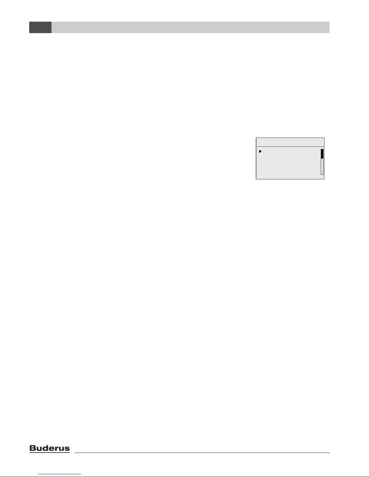
Display texts
Words appearing on the display are shown in bold in the text.
Example: USER MENU
standard display
operation modes
switching programme
sum./win. threshold
USER MENU
Logamatic EMS – 6 720 801 387 (2011/05)
5
Key to symbols and safety instructions
1
1 Key to symbols and safety instructions
1.1 Explanation of symbols
Warnings
Signal words at the start of a warning indicate the type and seriousness of the ensuing risk if
measures to prevent the risk are not taken.
• NOTE indicates that material losses may occur.
• CAUTION indicates that minor to medium injury may occur.
• WARNING indicates that serious injury may occur.
• DANGER indicates a risk to life.
Important information
Additional symbols
Warnings in this document are framed and identified by a warning triangle printed
against a grey background.
If there is a risk of electric shock, the exclamation mark in the warning triangle is
replaced by a lightning symbol.
Important information where there is no risk to people or property is indicated with the
adjacent symbol. It is bordered by lines above and below the text.
Symbol Explanation
B Action step
Æ Cross-reference to other parts of this document or to other documents
• List/list entry
– List/list entry (second level)
Table 1

Key to symbols and safety instructions
Logamatic EMS – 6 720 801 387 (2011/05)
6
1
1.2 Safety instructions
Installation and commissioning
B Observe these instructions to ensure satisfactory operation.
B The appliance must only be installed and commissioned by an authorised installer.
Risk of death from electric shock
B The power supply must be connected by a qualified electrician.
B Observe the connection diagram.
B Before installation: isolate all poles of the power supply (230 V AC). Secure against unintentional
reconnection.
B Never install this appliance in wet rooms.
B Never connect this appliance to the 230 V mains.
Damage through operator error
Operator errors can lead to injuries and/or material losses.
B Ensure that children never operate this appliance unsupervised or play with it.
B Ensure that only individuals who can operate this appliance correctly have access to it.
Warning: frost
The heating system can freeze up in cold weather if it is not in operation:
B Leave the heating system permanently switched on.
B Enable frost protection.
B In case of faults: remedy any faults immediately.

Logamatic EMS – 6 720 801 387 (2011/05)
7
Product information
2
2 Product information
2.1 Correct use
The RC35 programming unit must only be used to operate and control Buderus heating systems in
detached houses and residential buildings.
B Always use this appliance correctly and in conjunction with the specified control systems.
B Observe all regulations and standards applicable to the installation and operation of the system
in your country!
The boiler must be equipped with EMS (Energy Management System) or UBA1.x (Universal Burner
Automation).
Do not operate the programming unit with controllers of the Logamatic 2000/4000 control systems.
We recommend that you always operate the heating system with a programming unit (without a
programming unit only emergency mode is possible).
If RC2xremote programmers are used, which were manufactured up to and including 2005, only two
remote programmers can be connected. In case of related questions, please contact your local
Buderus sales office.
These instructions describe all possible functions of the RC35 programming unit. Some of these
functions may not be available, depending on which boiler (combustion controller) is used. You will
find information on this in the relevant chapter.
For information regarding the combustion controller, see menu DIAGNOSIS\VERSIONS
(Æ page 50).
RC35 as replacement for ERC
If the RC35 programming unit is used as a replacement for the ERC controller, there are differences
for example as regards the basic settings. For an overview of these, see Tab. 4, page 10.
2.2 EU Declaration of Conformity
The design and operation of this product conform to the European Directives and the supplementary
national requirements. Its conformity is demonstrated by the CE designation. You can call up the
Declaration of Conformity for this product on the internet at www.buderus.de/konfo or request a
copy from your local Buderus sales office.
2.3 Included in Delivery
• RC35 programming unit
• Operating instructions
• Installation and maintenance instructions
• Wall mounting base, fixing material
Product information
Logamatic EMS – 6 720 801 387 (2011/05)
8
2
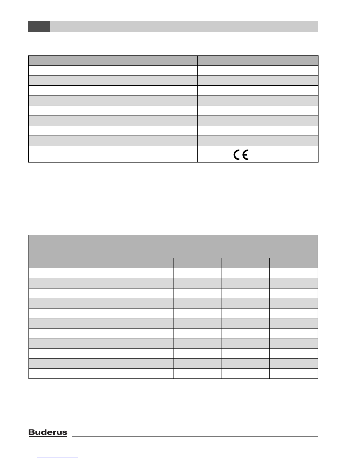
2.4 Specification
Temperature sensor characteristics
When measuring temperature sensors, observe the following requirements:
• Isolate the system before measuring.
• Measure the resistance at the cable ends.
• The resistances represent mean values and are subject to tolerances.
Unit RC35
Power supply via BUS system V 16 V DC
Power consumption W 0.3
Power consumption with backlighting W 0.6
Dimensions (width/height/depth) mm 150/90/32
Weight g 233
Operating temperature °C 0 to +50
Storage temperature °C 0 to +70
Relative humidity % 0 to 90
CE designation
Table 2 Specification - programming unit RC35
Outside temperature sensor
Flow temperature sensor
DHW temperature sensor
°C k Ω °C k Ω °C k Ω
– 20 96.358 10 19.872 60 2.49
– 15 72.51 16 15.699 65 2.084
– 10 55.054 20 12.488 70 1.753
– 5 42.162 25 10.001 75 1.481
0 32.556 30 8.060 80 1.256
5 25.339 35 6.535 85 1.070
10 19.872 40 5.331 90 0.915
15 15.699 45 4.372 95 0.786
20 12.488 50 3.606 100 0.677
25 10.001 55 2.989
30 8.060
Table 3 Resistances of the temperature sensors, for EMS only

Logamatic EMS – 6 720 801 387 (2011/05)
9
Product information
2
2.5 Validity of these instructions for function modules (accessories)
These instructions also apply to the programming unit when used in conjunction with the MM10
mixer module and the WM10 low loss header module.
Additional setting options may be found in some menus, if your heating system is equipped with
alternative function modules (e.g. solar module SM10). These setting options are explained in a
separate manual.
2.6 Accessories
For detailed information regarding suitable accessories, see the catalogue.
• Mixer module MM10
1)
for triggering a 3 way valve is not possible. A description of the MM10 is
included in the RC35 instructions.
• Switching moduleWM10
1)
for operation of a hydraulic low loss header
• Solar module and further EMS modules (e.g connection module ASM10)
1)
• Hybrid module HM10 for combined operation of the boiler with an air heating pump external unit.
• Remote programmer
1)
(e.g. RC2x,RC20/RF) for triggering one heating circuit at a time
• External temperature sensor
2)
, external room temperature sensor
1) With heating boilers with UBA1.x or DBA the use of modules
2) Required with weather compensated control.
Product information
Logamatic EMS – 6 720 801 387 (2011/05)
10
2
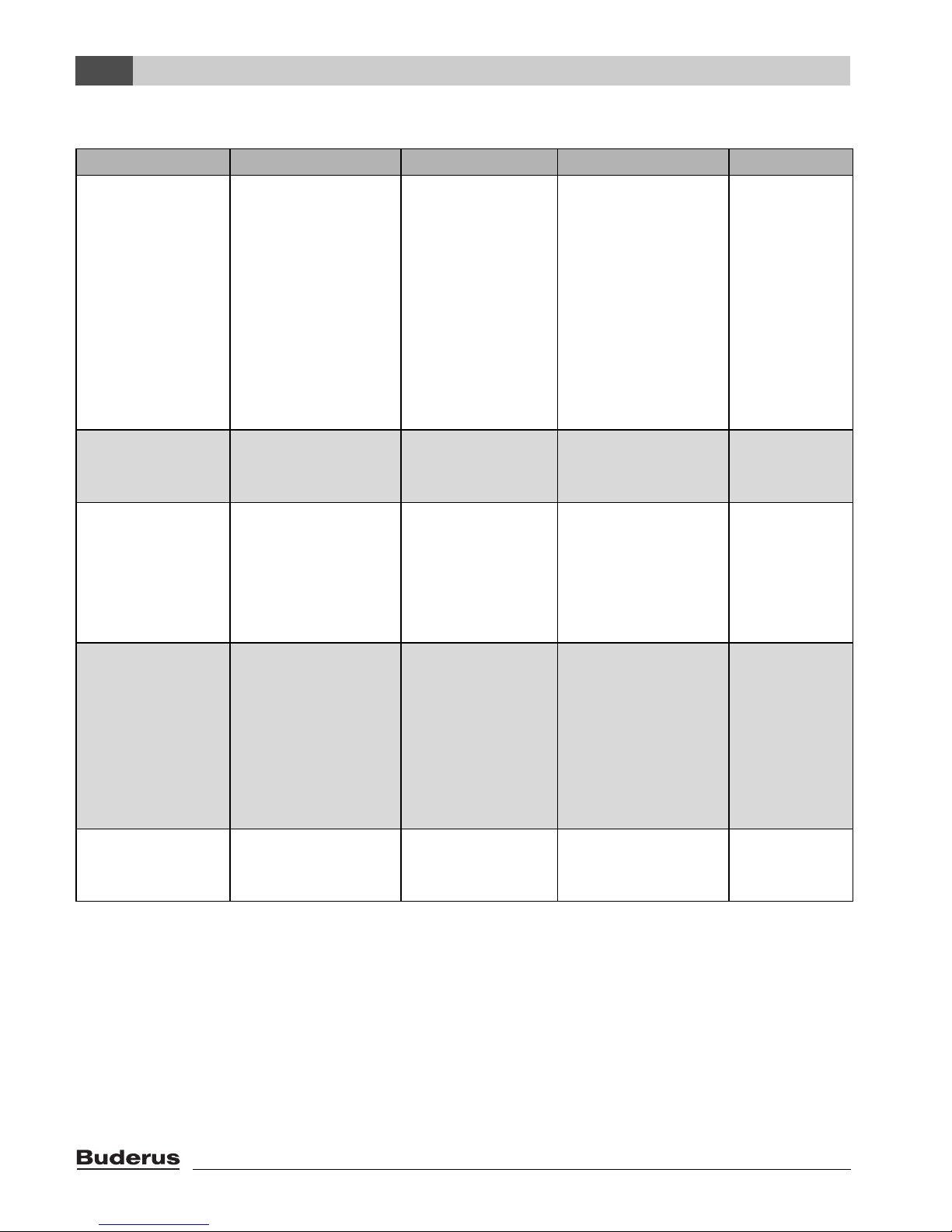
2.7 Replacement of ERC with RC35
Topic ERC RC35 Note See page
Setback modes
(night setback)
Changeover
between
“Shutdown” and
“Outdoor setback
mode” subject to
the selected outside
temperature
threshold.
Selection of four
setback modes:
• Reduced
operationShutdown
modeRoom
setback
modeOutdoor
setback mode
Deviation, e.g.
modified outside
temperature
threshold for outside
setback mode.
Settings at the
RC35 programming
unit possible as for
the ERC – requires
clarification with the
end user.
37 – 38
HS day,
night temperature
Day: 19/21 °C
Night: 16 °C
Day: 21 °C
Night: 17 °C
13
(operating
instructions)
Control method Room flow/room
output can be
changed over.
Room flow is the
default setting and
can only
be switched over
at the customer
service level.
If room output is to
be used, contact
your Buderus
customer service.
–
Self-test Self-test available
and can be
activated.
Permanent selftest in the
background - no
activation
required.
The RC35
programming unit
tests the system
continually If a fault
is found, the RC35
programming unit
automatically gives a
fault display.
–
Room
temperature hookup (control type)
HS = 3 K HS = 0 K 36
Table 4 Differences between ERC and RC35
Logamatic EMS – 6 720 801 387 (2011/05)
11
Installation
3
3 Installation
3.1 Choosing the right installation position
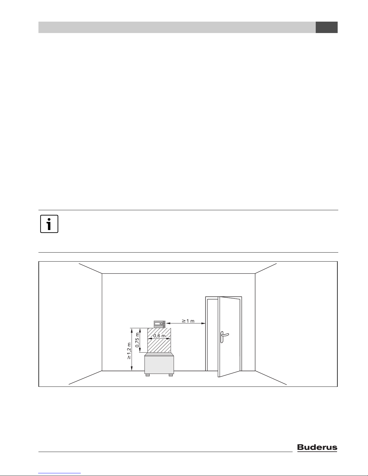
3.1.1 Installation in the reference room
If the system is operated in room temperature-dependent mode, observe the following requirements:
• Installation position on an internal wall (Æ fig. 1)
• Maintain the specified distance from the door (to avoid draughts).
• Allow clearance below the programming unit (Æ fig. 1, shaded area) to ensure correct
temperature measurement.
• The reference room (= installation room) must be as representative as possible of the entire
home. External heat sources in the reference room (e.g. sunlight or other heat sources such as
an open fire) affect the control functions. This means it may be too cold in rooms without external
heat sources.
• Always open the thermostatic radiator valves fully in the reference room to prevent the two
temperature controllers influencing each other.
Fig. 1 Minimum clearances for installation in a reference room
If there is no suitable reference room, we recommend setting the system to weathercompensated control instead (this requires an outside temperature sensor).
Alternatively, you could install an external room temperature sensor in the room with the
greatest heat demand (e.g. living room).
6 720 618 477-01.1RS

Installation
Logamatic EMS – 6 720 801 387 (2011/05)
12
3
3.1.2 Installation on boiler
Installation directly on the boiler is possible where the boiler is equipped with the Energy
Management System (EMS).
The outside temperature sensor for weather-compensated control is not delivered as standard, but
can be ordered as an accessory.
3.2 Types of installation
The programming unit can be installed in three different ways:
• As the only programming unit in the system (basic setting): the programming unit is installed in a
living room (reference room) or on the boiler
1)
.
Example: single family house with one heating circuit.
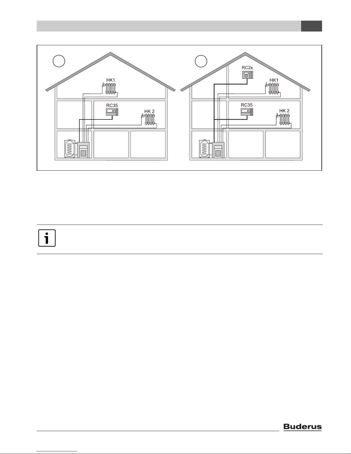
• As the only programming unit in a heating system with two or more heating circuits
2)
(Æ fig. 2, [1]).
Examples: underfloor heating on one storey, radiators in the others, or a home combined with a
separate dwelling unit or with a medical practice room.
• In association with a remote programmer (e.g.RC2x, RC20/RF, fig. 2, [2]) In this case there are
always two separate heating circuits. Remote control units cannot be used for boilers with
UBA1.x.
Examples: underfloor heating on one floor, radiators on the others; or a main flat together with a
separate granny flat or doctor's surgery.
If a HM10 hybrid module is used, the installation must be carried out with the wall
bracket. If it is installed on the boiler, it does not function correctly.
1) Not possible if the HM10 hybrid module is used
2) Not possible with boilers with UBA1.x and DBA.
Logamatic EMS – 6 720 801 387 (2011/05)
13
Installation
3
Fig. 2 Options for a heating system with two heating circuits
1 Both heating circuits are controlled by one programming unit.
2 Each heating circuit has its own programming unit / remote control unit.
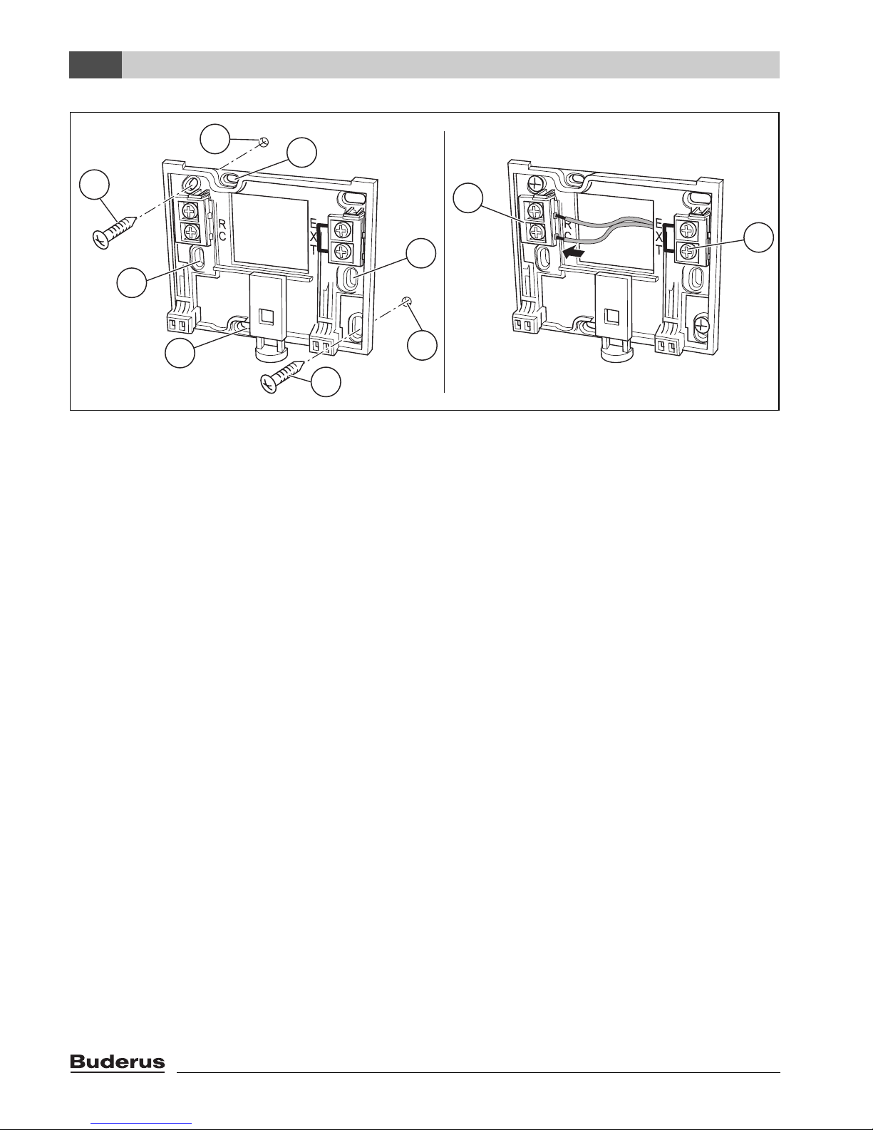
3.3 Installation and connections
The wall bracket can be attached directly to the wall or on a flush-mounting box.
When mounting on a flush box, note the following:
B Draught from within the flush box must not be able to falsify the capture of the room temperature
by the programming unit.
If required, stuff the flush box with insulation material.
B Use horizontal or vertical fixing holes [4].
B Fit the wall mounting base (Æ fig. 3, left).
B Connect a two-core BUS cable from the Energy Management System (EMS) to the “RC” cable
terminals [5].
– Cable type: 2 x 0.75 mm
2
(0.5 – 1.5 mm2), max. length 100 m
– Polarity is irrelevant for the two wires.
B Do not lay the cables parallel to power cables.
Only use the wall mounting base with screw terminals.
B Replace wall mounting bases without screw terminals that may already be installed.
6 720 641 642-01.1RS
2
1
Installation
Logamatic EMS – 6 720 801 387 (2011/05)
14
3
Fig. 3 Mounting the wall mounting base (left) and connecting the wires (right)
1 Hole drilled in the wall
2 Screws (included with the unit) for surface-mounting on the wall
3 Vertical mounting holes for mounting on a flush box
4 Horizontal mounting holes for mounting on a flush box
5 “RC” connection to the EMS (boiler)
6 “EXT” terminals for external room temperature sensor or for jumper
B If the RC35 programming unit is operated without external room temperature sensor, a jumper is
required at the “EXT” cable terminals [6] (condition as supplied from the factory).
B If the RC35 programming unit operates together with an external room temperature sensor,
remove the factory-fitted jumper at “EXT” and connect the external room temperature sensor in
its place.
6 720 618 477-03.1RS
2
2
3
3
4
4
5
6
1
1
Logamatic EMS – 6 720 801 387 (2011/05)
15
Installation
3
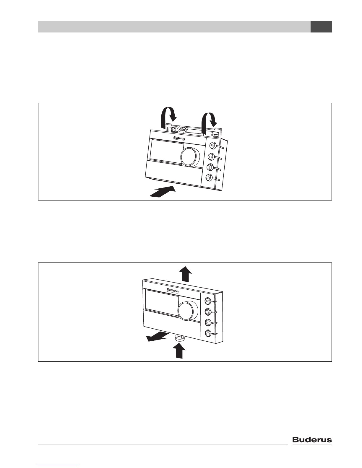
3.4 Hooking in or removing the programming unit
Hooking in the programming unit
1. Hook the programming unit at the top into the mounting plate in the direction of the arrows.
2. Push the programming unit at the bottom in the direction of the arrow against the mounting plate
until it clicks into place.
Fig. 4 Hooking in the programming unit
Removing the programming unit
1. Press the key underneath the mounting plate in the direction of the arrow.
2. At the same time pull the programming unit forwards.
3. Remove the programming unit by lifting upward.
Fig. 5 Removing the programming unit
6 720 618 477-04.1RS
2.
1.
6 720 618 477-10.1RS
3.
2.
1.
Principles of operation
Logamatic EMS – 6 720 801 387 (2011/05)
16
4
4 Principles of operation
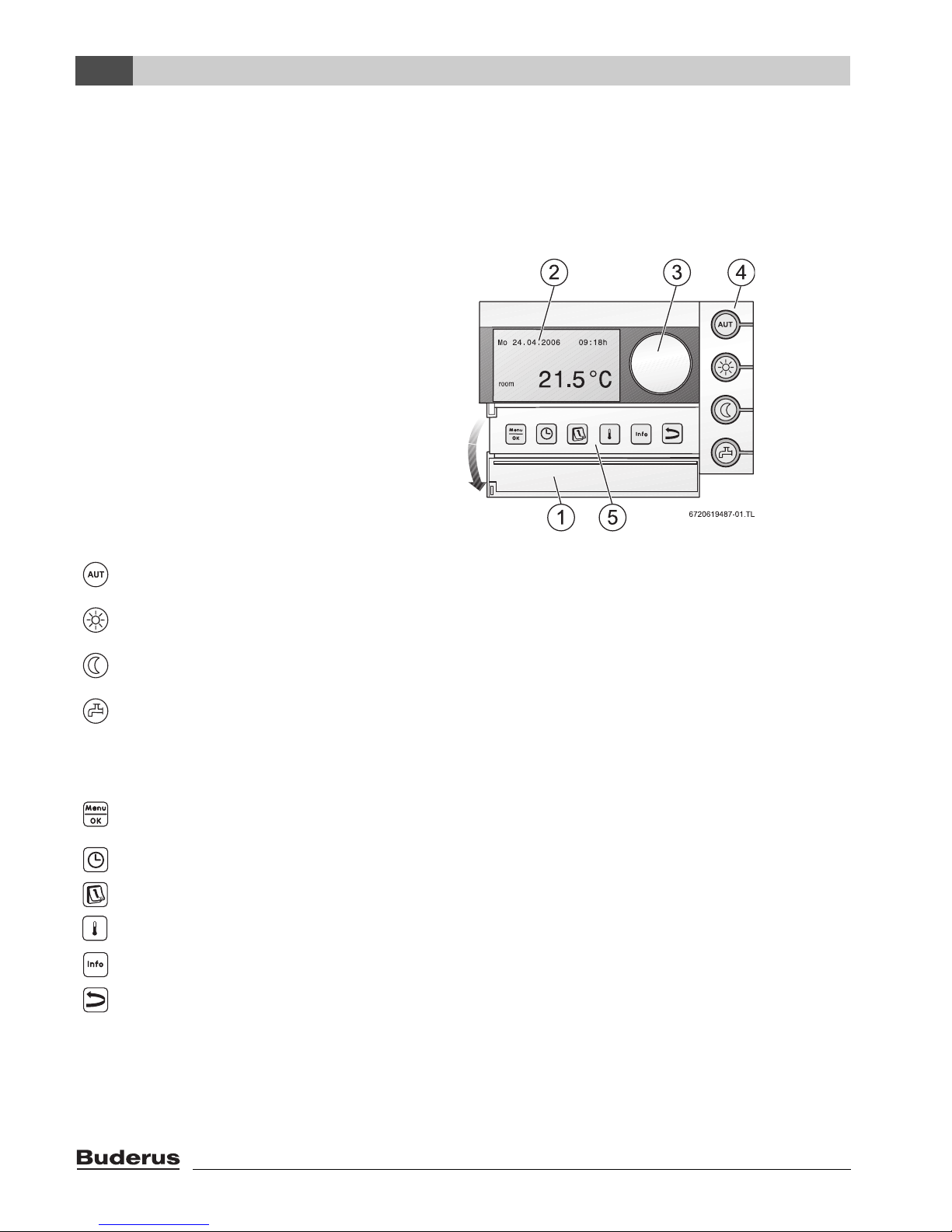
4.1 Overview of controls
Key to diagram:
1 Flap; pull the recessed grip
on the left to open
2 Display
3 Rotary selector for changing values
and temperatures or for moving within
the menus
4 Keys for basic functions: When the LED lights up,
“AUT” (automatic) • the switching program is active (automatic changeover between day and
night room temperatures).
“Day mode” (manual) • the heating system operates at the set day room temperature. The DHW
is switched on (basic setting).
“Night mode” (manual) • the heating system operates at the set night room temperature. Frost
protection is active. DHW heating is off (default setting).
“DHW” • the DHW temperature has fallen below its set value. Pushing this key
means DHW will be heated up again (the LED flashes during heat-up).
5 Keys for
additional functions:
Function:
“Menu/OK” Open the user menu and confirm the current selection.
When the rotary selector is turned simultaneously: change setting.
“Clock time” Set the time.
“Date” Set the date.
“Flow/returntemperature” Set the room temperature.
“Info” Open the Info menu (to view values).
“Back” Go back one step or one menu item.
In automatic mode the LED for the display of the current operating condition (“day” or “night”) also lights up in addition to the
LED “AUT”. Exception: with boilers with UBA1.x only the LED “AUT” lights up. The “DHW” LED can also be switched off. With
boilers with UBA1.x the “DHW” LED does not light up at all.
Logamatic EMS – 6 720 801 387 (2011/05)
17
Principles of operation
4
4.2 Introduction to the service menu
You can use the SERVICE MENU to set the parameters for the system. It also contains functions
for diagnosis, maintenance purposes, and carrying out a reset. The procedure for operation is
always the same:
1. Open the flap (by pulling the recessed grip on the left).
2. Press + + simultaneously to open the SERVICE MENU.
3. Turn the rotary selector to change the selection.
4. Press to make your selection.
5. To change the value, hold down the button (the value starts flashing) and turn the rotary
selector at the same time. Release the button.
The modified value is saved.
6. Press the button to go back one step.
Press the button several times or close the flap to show the standard display again.
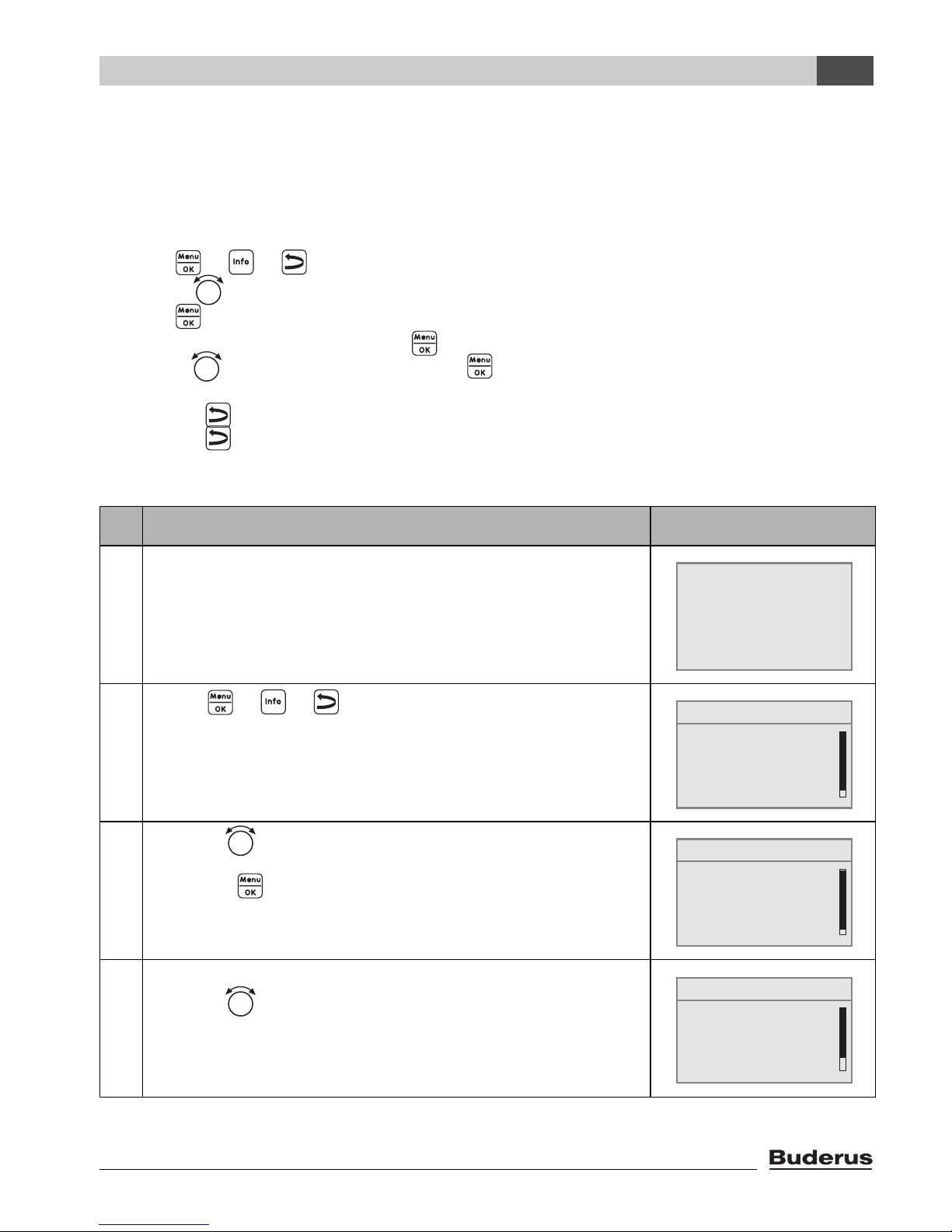
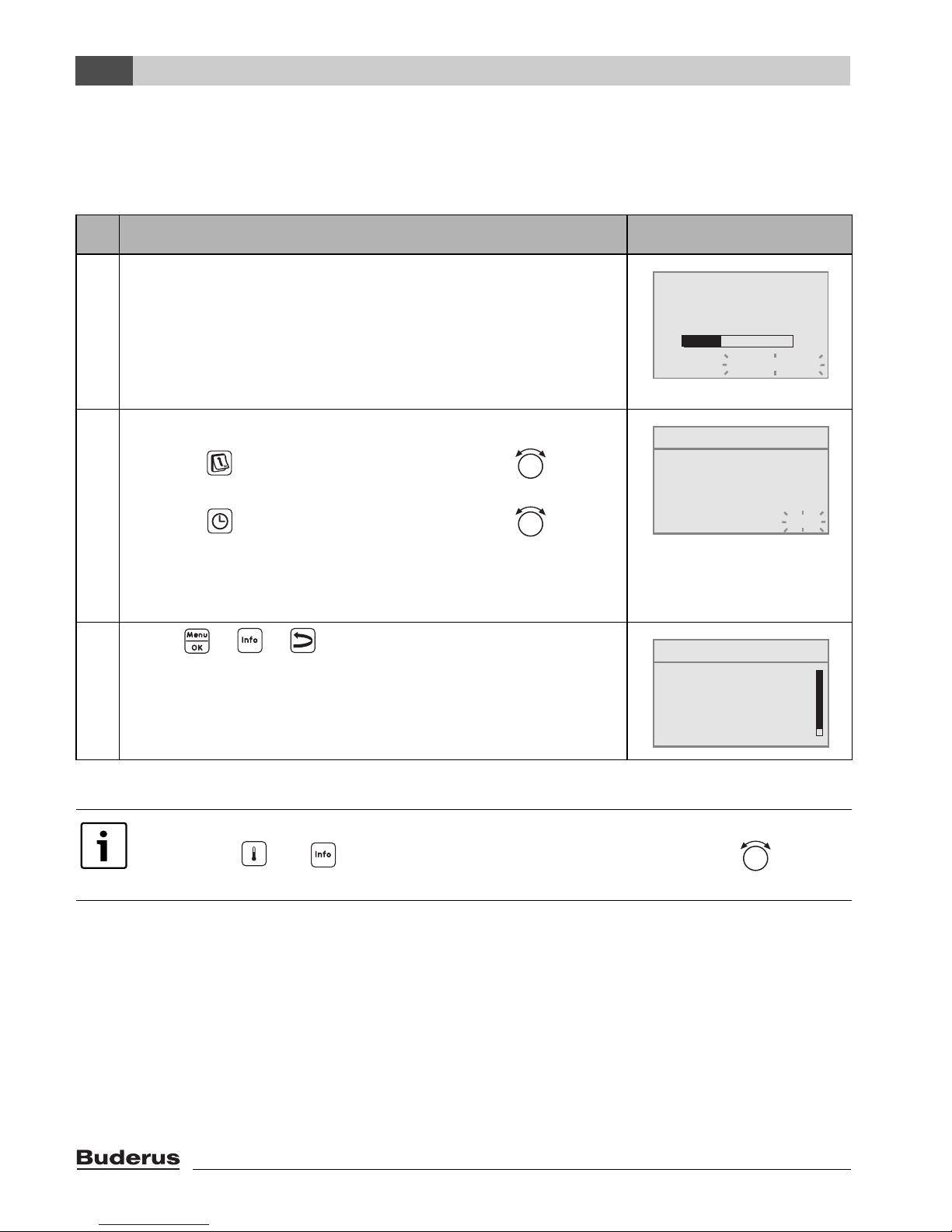
Example: Setting the building type (adjusted time)
Operation Result
1. Open the flap (by pulling the recessed grip on the left).
2. Press + + simultaneously,
to open the SERVICE MENU.
3. Turn the rotary selector to the left until settings is
selected.
Press the button to confirm the selection.
4. The SERVICE\SETTINGS menu is opened.
Turn the rotary selector to the left until boiler data is
selected.
Table 5 How to use the service menu (example)
6° 02.12.2005 10:20h
Temp. Exterior -1°C
21.5°C
SERVICE MENU
B
quick operation
settings
diagnosis
servicing
SERVICE MENU
quick operation
settings
diagnosis
servicing
B
SERVICE\SETTINGS
B
plant data
boiler data
domestic hot water
heating circuit 1
Principles of operation
Logamatic EMS – 6 720 801 387 (2011/05)
18
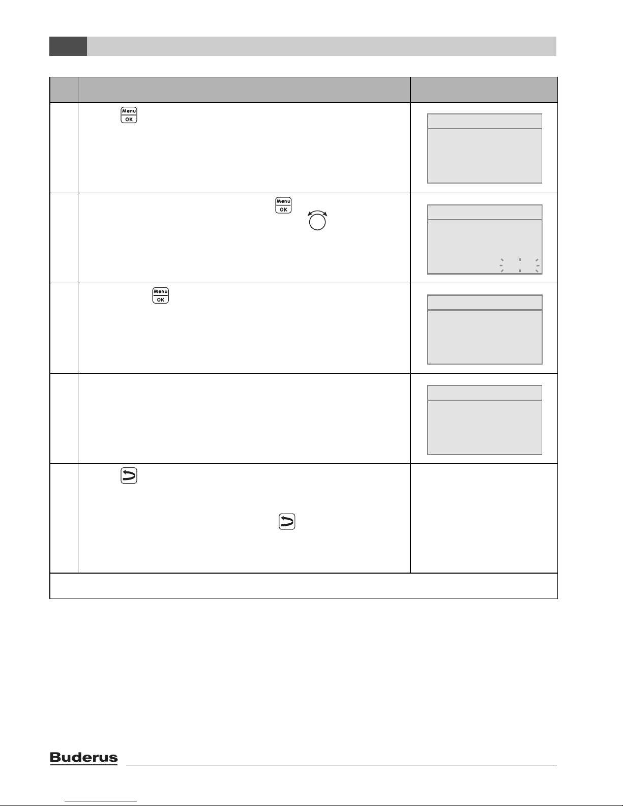
4
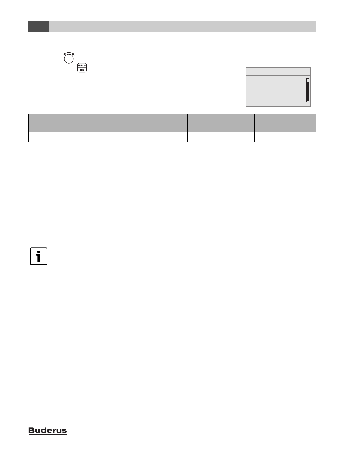
5. Press to select boiler data.
The menu SETTINGS\BOILER is opened.
6. To change the value, hold down the button (the value
starts flashing) and turn the rotary selector at the same
time.
7. Release the button.
The value stops flashing. The modified value is saved.
8. If you have carried out this example as practice only, make
sure that the original setting is retained.
To do so, repeat steps 6 and 7 if necessary.
9. Press to go back one step.
-or-
To finish entering the settings: press several times or
shut the flap.
The standard display reappears.
You can enter all settings in the SERVICE MENU using this procedure.
Operation Result
Table 5 How to use the service menu (example)
SETTINGS\BOILER
What type of building
do you have?
medium
SETTINGS\BOILER
What type of building
do you have?
medium
SETTINGS\BOILER
What type of building
do you have?
light
SETTINGS\BOILER
What type of building
do you have?
medium

Logamatic EMS – 6 720 801 387 (2011/05)
19
Principles of operation
4
4.3 Overview of the service menu
The SERVICE MENU is divided into the following menus and submenus:
Menu Sub-menu Contents/function Page
Quick operation The most important parameters from the
“settings” menu to configure the heating
system
22
Settings (all
parameters)
Plant data
1)
1) Limited use depending on the boiler used.
Parameters: language, number of heating
circuits, installed modules, building type,
minimum outside temperature
26
Hybrid If HM10 hybrid module is installed: see
documents on the hybrid system
29
Boiler data
1)2)
2) May not be available or possible, depending on the boiler used.
Parameters: pump run-on time and modulation 30
Heating circuit
data
1)
Parameters of the installed heating circuits 31
Domestic hot
water
1)
Parameters for DHW 40
Solar data
2)
If solar is installed: see documentation for the
solar module
43
RC35 calibration Parameters: calibration of the displayed room
temperature
44
Contact details Entering the heating contractor's name and
telephone number
45
Diagnosis Function test
1)2)
Activating individual components for test
purposes
47
Monitor value Viewing target values and actual values 48
Error message
1)
Viewing faults 49
Heating curve Display the set heating curve graphically 50
Versions Viewing software versions 50
Service
1)2)
Maintenance interval Setting times for maintenance, by hours run or
by date
51
Current messages Viewing service messages 51
RESET servicing Resetting service messages 51
Reset
1)
Factory setting Resetting of parameters to basic settings 52
Error list 52
Service message 52
Working hours 52
Table 6 Service menu navigator
Commissioning
Logamatic EMS – 6 720 801 387 (2011/05)
20
5
5 Commissioning
5.1 General commissioning
Operation Result
1. Switch on the heating system.
While setting up the connection between the RC35 and EMS
or UBA1.x, the display shows the message on the right.
If the display shows a different message, look it up in
Chapter 10, page 53.
2. Set the date and time:
Hold the button pressed down and with the rotary
selector set the respective flashing value. Release button.
Hold the button pressed down and with the rotary
selector set the respective flashing value. Release button.
In the event of a power failure, the date and time are retained
for up to 8 hours. All other settings are saved.
3. Press + + simultaneously,
to open the SERVICE MENU.
Table 7 General commissioning
If necessary, you can change the contrast on the display:
B Hold the and buttons pressed down and simultaneously turn the rotary
selector.
RC35 version:
connect to:
connection setup ...
please wait
SET DATE
set year
01.01.2000
SERVICE MENU
B
quick operation
settings
diagnosis
servicing

Logamatic EMS – 6 720 801 387 (2011/05)
21
Commissioning
5
5.2 Checklist: important parameters for commissioning
When commissioning the device, ensure the satisfaction of both parties, making sure that the
heating system meets the customer's needs and will not give cause for complaints. In our
experience, the following parameters are very important for the satisfaction of the system user:
B Find out the system owner's requirements and preferences regarding:
Setting options
Standard
setting
SERVICE
MENU\
Settings\
The required type of reduction
(night setback)
Outdoor setback
mode; Reduced
operation; Room
setback mode; Shutdown mode
Outdoor
setback
mode
Heating circuit x,
page 32
The required control mode Outside temperature
compensated, room
temperature
compensated
Outside
temperature
compensated
Heating circuit x,
page 35
of the correct heating curve
By means of the
following parameters:
design temperature,
minimum outside
temperature, offset, and
set room temperature
Heating circuit x,
page 32
of the correct building type
(damping of the outside
temperature)
Light, medium, heavy Medium Plant data,
page 27
of the switching frequency of the
circulation pump.
1)
1) This function is not possible with boilers with UBA1.x, DBA, UBA-H3 or with DHW with
instantaneous water heating.
Permanent operation,
1 x, 2 x, 3 x, 4 x, 5 x, 6 x
per hour for 3 minutes
at a time
2 x DHW, page 41
DHW priority Yes, No Yes Heating circuit x,
page 33
Switching program
(times)
Standard program
(e.g. family), user
defined program
Family Heating circuit x,
page 34
Table 8 Checklist: important parameters for commissioning

Commissioning
Logamatic EMS – 6 720 801 387 (2011/05)
22
5
5.3 Quick start-up (quick programmer menu)
B Press button to open the quick operation menu.
SHORTPROG\ Menu item Input range
Standard
setting Other information
LOW LOSS
HEADER
Have you installed a
module for the
hydraulic low loss
header?
Yes, No no In association with
MCM10 the setting is
automatically set to
“Yes”the screen is
hidden.
1)2)
Is a sensor for the low
loss header
connected?
No, at the
boiler, at the
low loss
header
module
no If a low loss header
module is used, connect
the temperature sensor
to the low loss header
module.
3)
SYSTEM Is heating circuit 1
installed (unmixed
heating circuit)?
Yes, No Yes
NO. OF MIXERS How many mixed
heating circuits are
installed?
0 to 3 0 Set the address on the
rotary coding selector of
the mixer module (basic
setting HK2).
1)
HEATING CIRCUIT
1
(and other heating
circuits)
Which operating unit
is assigned to heating
circuit 1?
RC2x/
RC20/RF,
RC35, none
RC35 Assigning programming
units to heating circuits
(Æ page 35). General
heating circuit data (Æ
page 31).
Set up any other heating
circuits as per heating
circuit 1.
How should heating
circuit 1 be
controlled?
Outside
temperature
compensate
d, room
temperature
compensate
d
Outside
temperatur
e
compensat
ed
Which heating system
does heating circuit 1
have?
Radiator,
convector,
floor
Radiator Heating curve (Æ
page 36)
Table 9 Quick programmer menu navigator
SERVICE MENU
B
quick operation
settings
diagnosis
servicing

Logamatic EMS – 6 720 801 387 (2011/05)
23
Commissioning
5
DHW Have you installed
domestic hot water?
Yes, No no
4)
What should be used
for domestic hot
water heating?
3-way
diverter valve
cylinder
primary
pump
Three-way
diverter
valve
5)
To which temperature
should your domestic
hot water be heated?
30 °C to
80 °C
60 °C In order to be able to
change the DHW
temperature, set the
DHW on the boiler
programming unit to
“AUT” or activate DHW.
SOLAR MODULE Have you installed a
solar module?
Yes, No no
1)
1) Not possible or not available with boilers with UBA1.x or DBA.
2) Not possible with boilers with UBA4.
3) Only possible with boilers with UBA4
4) Not possible or not available with boilers with DBA.
5) Not available with boilers with UBA1.x, DBA or UBA-H3.
Check whether further settings are required using the checklist on page 21.
SHORTPROG\ Menu item Input range
Standard
setting Other information
Table 9 Quick programmer menu navigator

Commissioning
Logamatic EMS – 6 720 801 387 (2011/05)
24
5
5.4 Detailed commissioning
B Check whether the basic settings in the SERVICE\SETTINGS menu match the heating system.
B Note down modified settings if needed.
5.5 System handover
B Ensure that no temperature limits for central heating and DHW have been set at the boiler
programming unit, so DHW and flow temperature can be regulated via the RC35 programming
unit.
B Explain to the customer how the appliance works and how to operate it.
B Inform customer about the selected settings.
5.6 Shutting down/switching off
The RC35 programming unit is powered via the heating system and remains permanently on. The
heating system is only switched off for maintenance work, for example.
B For switching the heating system on or off: switch the On/Off switch on the boiler programming
unit to position 1 (ON) or 0 (OFF).
B With hybrid systems with HM10: shut off power to the hybrid module.
We recommend that you hand over these installation and maintenance instructions to
the customer for safe keeping at the heating system.
After shutting down or in the event of a power failure, the date and time are retained for
up to 8 hours. All other settings are retained permanently.

Logamatic EMS – 6 720 801 387 (2011/05)
25
Commissioning
5
5.7 Operating information
Subscribers on the EMS-BUS
In a BUS system, only one subscriber can carry out the calculations for a heating circuit.
Consequently, only one RC35 programming unit may be installed in each heating system. If
additional programming units (e.g. RC2x) are required, they must be installed as remote
programmer
1)
with a set heating circuit address (Æ page 31).
Thermostatic radiator valves in the reference room
Thermostat valves on the radiators in the reference room2) are not required with room temperature
compensated control. Fully open any thermostatic radiator valves in the reference room.
Anti-block protection
1)
In all operating modes all heating pumps are switched on for 10 seconds and then switched off
again each Wednesday at 12:00 o'clock, in order to prevent damage to the pumps. The mixers are
then set to "OPEN" for 10 seconds and then "CLOSED". All pumps and mixers then return to their
normal, regulated operation.
1) this function is not possible with boilers with UBA1.x or DBA)
Disable this on boilers with integral weather-compensated control.
2) room in which a RC35 or RC2x/RC20/RF is fitted)

System settings (Service menu – Settings)
Logamatic EMS – 6 720 801 387 (2011/05)
26
6
6 System settings (Service menu – Settings)
B Press + + simultaneously, to open the SERVICE MENU.
B Turn the rotary selector to the left until settings is selected.
B Press to open menu SERVICE\SETTINGS.
6.1 System data
B Press button to select plant data.
The menu SETTINGS\SYSTEM opens.
Note that the menu items shown will vary depending on the heating system.
Menu item
Input
range
Standard
setting
Other information
Have you installed a module for
the low loss header?
Yes, No No In association with MCM10 the
setting is automatically set to “Yes”;
screen is hidden.
1)2)
Is a sensor for a low loss header
connected?
No,
at the
boiler, at
the low loss
header
module
No If a low loss header module is used,
connect the temperature sensor to
the low loss header module.3)
4)
Is heating circuit 1 installed
(unmixed heating circuit)?
Yes, No Yes
How many mixed heating circuits
are installed?
0 to 3 0 Setting the address on the rotary
coding selector of the mixer module
(basic setting HK2).
1)
Have you installed a solar
module?
Yes, No No
1)
Table 10 Navigator for service menu SETTINGS\SYSTEM
SERVICE MENU
quick operation
settings
diagnosis
servicing
B
SERVICE\SETTINGS
B
plant data
boiler data
domestic hot water
heating circuit 1

Logamatic EMS – 6 720 801 387 (2011/05)
27
System settings (Service menu – Settings)
6
6.1.1 Building type (adjusting the outside temperature)
A building's heat storage capacity and its characteristic resistance to heat transfer will delay the
effect of outside temperature fluctuations on the rooms inside. Consequently, it is not the current
outside temperature that is crucial but the so-called adjusted outside temperature. Parameter
building type enables the adjustment to be applied that takes account of the fluctuating outside
temperatures. This enables the control to be matched to the characteristics of the building.
The control unit calculates the time constant for adjusting the outside temperature, using the factor
given in Tab. 11 for the stated building type and an internal multiplier, the "runtime" (= 6 minutes).
The time constant is the product of: factor x runtime = adjustment time constant in hours.
Should the adjusting of the
outside temperature be switched
off?
Yes, No No When selecting “yes” the following
parameter building type will be
hidden.
What type of building do you
have?
Light,
medium,
heavy
Medium Building type (heat storage capacity),
Æ Chapter 6.1.1, page 27.
What is the lowest expected
outside temp. in your region?
– 30 °C to
0°C
– 10 °C Æ Chapter 6.1.2, page 28
1) Not possible or not available with boilers with UBA1.x or DBA.
2) Not possible with boilers with UBA4
3) Only possible with boilers
4) UBA4
Parameter:
building type Type Factor
Light E.g. prefabricated building, wood-frame construction 10
Medium e.g. house made of hollow blocks (basic setting) 30
Heavy E.g. brick house 50
Table 11 Calculating the adjustment time constant
Menu item
Input
range
Standard
setting Other information
Table 10 Navigator for service menu SETTINGS\SYSTEM

System settings (Service menu – Settings)
Logamatic EMS – 6 720 801 387 (2011/05)
28
6
Example:
Fig. 6 This greatly simplified example shows how the adjusted outside temperature follows the
outside temperature, but does not reach its extreme values.
1 Current outside temperature
2 Adjusted outside temperature
6.1.2 Minimum outside temperature
The minimum outside temperature is the average value of each of the coldest outside temperatures
or recent years, and it has an influence on the heating curve. The value can be taken from the heat
demand calculation which should be done for every building, or from the climatic zone chart for your
region.
In the basic setting any changes in the outside temperature have an effect after a delay
of three hours at the latest (30 x 6 minutes = 180 minutes) on the calculation of the
outside temperature compensated control.
B To control the calculated, adjusted outside temperature and the actual measured
outside temperature: open the menu for Diagnostics\monitor value 4
boiler\burner.
6 720 618 477-05.1RS
2
1

Logamatic EMS – 6 720 801 387 (2011/05)
29
System settings (Service menu – Settings)
6
6.2 Hybrid
B Turn the rotary selector to the left until Hybrid is selected.
B Press to select Hybrid.
The SETTINGS\HYBRID menu is opened
Menu item Input range Standard setting
Other
information
Is there a buffer in the
system?
Yes, No no
Triggering of boiler / heat
pump depends on:
Environmental factors,
costs, switching threshold,
environment and costs
Environment
Energy price ratio for
electricity / fossil fuel
0.0 to19.9 3.3
What is the primary energy
factor for the fossil fuel?
0.0 to 5.0 1.1
What is the primary energy
factor for the electrical
energy?
0.0 to 5.0 2.6
What should the dual-mode
switching threshold be?
-20 °C to +20 °C +6 °C
How is the pump on the
HM10 integrated
hydraulically?
serial, parallel serial
By what amount of time
should the boiler switch-in
be delayed?
5 to 120 minutes
Temperature difference for
delayed boiler switch-in?
1K to 99K
Table 12 Navigator for Service menu\Settings\Hybrid
You can find explanations on the settings in the documents for the hybrid system.
plant data
SERVICE\SETTINGS
B
hybrid
boiler data
heating circuit 1

System settings (Service menu – Settings)
Logamatic EMS – 6 720 801 387 (2011/05)
30
6
6.3 Boiler data
B Turn the rotary selector to the left until boiler data is selected.
B Press to select boiler data.
The menu SETTINGS\BOILER is opened.
Menu item Input range
Standard
setting
Other information
Boiler pump after-run time
after burner stops?
deactivated,
1 to 60
minutes,
24 hours
5 min Setting is only possible with boilers
with internal pump.
1)
1) Not possible or not available with pumps with UBA1.x.
Set the pump logic
temperature.
0 to 65 °C 47 °C Setting only possible in conjunction
with BRM10.
Table 13 Navigator for service menu SETTINGS\BOILER
SERVICE\SETTINGS
B
plant data
boiler data
domestic hot water
heating circuit 1

Logamatic EMS – 6 720 801 387 (2011/05)
31
System settings (Service menu – Settings)
6
6.4 Heating circuit data
This chapter explains the settings for all heating circuits using heating circuit 1 as an example.
B Turn the rotary selector to the left until heating circuit 1 is selected.
B Press to select heating circuit 1.
The menu for SETTING\HEATING CIRCUIT 1 is opened.
Menu item Input range
Standard
setting Other information
Do you want to enable
heating circuit 1?
Yes, No Yes
Which programming unit
is assigned to heating
circuit 1?
RC2x/RC20/RF,
RC35, none
RC35 See page 35. With UBA1.xyou can
not select RC2x.
With selection of“None”the control
mode is switched to“Outside
temperature” compensatedand it is
hidden.
How should heating
circuit 1 be controlled?
Outside
temperature
compensated,
room temperature
compensated
Outside
temperature
compensated
“Room temperature compensated”
can only be set if RC2x or RC35 has
been allocated. If “room temperature
compensated” is selected, room
flow is used.
Which heating system
does heating circuit 1
have?
Radiator,
convector, floor
Radiator With HK1 “underfloor” setting only if
it is a case of a oil/gas condensing
boiler. Additional heating circuits
can then be installed.
Use a safety thermostat with
underfloor heating systems.
Table 14 Navigator for service menu of SETTING\HEATING CIRCUIT 1
SERVICE\SETTINGS
B
plant data
boiler data
domestic hot water
heating circuit 1

System settings (Service menu – Settings)
Logamatic EMS – 6 720 801 387 (2011/05)
32
6
Heating curve
Std. tmp. ( – 10 °C) 30 °C to 90 °C 75 °C
(radiator,
convector)
45 °C
(floor)
The value in brackets is the setting
for the minimum outside
temperature (Æ page 31). Setting
only if the control mode is set to
“outside temperature
compensated”(Æ page 36).
Max flow temp. Radiators,
convectors: 30 °C
to 90 °C.
1)
Underfloor heating:
30 °C to 60 °C
Radiators,
convectors:
75 °C
Underfloor
heating:
50 °C
Setting only if the control mode is
set to“outside temperature
compensated”(Æ page 36).
Enter the maximum
flow temperature:
Setting only if the control mode is
set to“room temperature
compensated”(Æ page 36).
Min flow temp. 5 °C to 70 °C 5 °C Setting only if the control mode is
set to“outside temperature
compensated”(Æ page 36)
Enter the minimum flow
temperature:
Setting only if the control mode is
set to“room temperature
compensated”(Æ page 36).
Rm. tmp. offset -5.0 K to +5.0 K 0.0 K Offset of heating curve.
Setting only if the control mode is
set to “outside temperature
compensated”(Æ page 36).
Enter the maximum room
influence:
0 K to 10 K 3 K Setting only if the control mode is
set to “outside temperature
compensated”(Æ page 35).
Which reduction mode
should be implemented?
Outdoor
compensation
mode,
reduced mode,
room compensation
mode (only if RC35
or RC2x have been
allocated to the
heating circuit),
switch-off mode
Outdoor
setback
mode
Night reduction
(Æ page 37)
Menu item Input range
Standard
setting Other information
Table 14 Navigator for service menu of SETTING\HEATING CIRCUIT 1

Logamatic EMS – 6 720 801 387 (2011/05)
33
System settings (Service menu – Settings)
6
What outside temp.
should be used for
reduced operation?
– 20 °C to +10 °C 5 °C Temperature threshold for outdoor
setback mode (Æ page 37).
Adjustment only if the setback mode
is set to “outdoor setback mode”.
Frost prot.
What temp. should be
used to trigger frost
protection?
Outside
temperature, room
temperature, no
frost protection
Outside
temperatur
e
Room temperature adjustment only
if RC2x or RC35 have been
assigned to the heating circuit
(Æ page 38).
Which frost protection
temp. should be used?
-20 °C to +10 °C 5 °C Refers to outside temperature
(Æ page 38).
From which outside
temperature should the
reduction be
interrupted?
OFF,
-30 °C to +10 °C
OFF Reduction in accordance with
DIN 12831 (Æ page 39).
Should domestic hot
water priority be
activated?
Yes, No no
Mixer
2)
Is a mixer installed? Yes, No Yes Can only be set for heating circuit 2
onwards.
2)
What running time
does the mixer have?
10 s to 600 s 120 sec.
2)
What increase should
be used for the boiler?
0K to 20K 5K
2)
Screed drying
2)
Should a drying cycle
be carried out?
Yes, No no Adjustment only if floor has been
selected. DHW heating is not
enabled while screed is drying.
2)
Every how many days
should the flow temp.
be raised?
Every day, every
2nd day to
every 5th day
Every day
2)
By how many Kelvin
should the flow
temperature be
increased in each
case?
0K to 40K 5K
2)
Menu item Input range
Standard
setting Other information
Table 14 Navigator for service menu of SETTING\HEATING CIRCUIT 1

System settings (Service menu – Settings)
Logamatic EMS – 6 720 801 387 (2011/05)
34
6
What is the desired
maximum flow
temperature?
25 °C to 60 °C 45 °C
2)
For how many days
should maximum flow
temp. be maintained?
0 days to 20 days 4 days
2)
Every how many days
should the flow temp.
be reduced?
Direct normal
operat., every day,
every 2nd day to
every 5th day
Every day
2)
By how many K should
the flow temperature
be reduced
respectively?
0 K to 20 K 5 K Adjustment only if, for flow
temperature reduction,“direct
normal operation” has not been
selected.
4)
Do you wish to change
the switching program?
Yes, No no When selecting “yes” the system
jumps to the heating circuit
switching program.
Should the switching
programme be
optimised?
Yes, No no Start and stop times are
automatically adjusted according to
the outside temperature, room
temperature and building type (heat
storage capacity).
What reduction mode
should be used for
holiday?
Outdoor
compensation
mode,
reduced mode,
room compensation
mode, switch-off
mode
Outdoor
setback
mode
See page 37.
Setting for “room compensation
mode” only if a remote programmer
(e.g. RC2x) has been allocated to
the heating mode. If “reduced
mode” is selected, the normal night
temperature is used.
What outside temp.
should be used?
-20 °C to +10 °C 5 °C Temperature threshold for outdoor
setback mode (Æ page 37).
Adjustment only if setback mode for
holiday was set to “outdoor setback
mode.”
1) Depending on the boiler the setting range can be limited
2) Not possible or not available with boilers with UBA1.x or DBA.
Menu item Input range
Standard
setting Other information
Table 14 Navigator for service menu of SETTING\HEATING CIRCUIT 1

Logamatic EMS – 6 720 801 387 (2011/05)
35
System settings (Service menu – Settings)
6
6.4.1 Assignment of programming unit / remote control unit in the software
This function is not available with boilers with UBA1.x and DBA.
Example: heating system with heating circuit 1 and heating circuit 2 (Æ page 12)
6.4.2 Control mode (outside temperature compensated/room influence)
In the Logamatic control unit the heating curve specifies the temperature of the heating water in the
boiler. It can be selected whether this heating curve is influenced solely by the outside temperature,
or whether a mix from the characteristics of the outside temperature and the room temperature
define the heating curve.
• Outside temperature compensated: with this setting a boiler temperature, which is
calculated in the control unit, is controlled by means of a change in the adjusted outside
temperature combined with selected settings for room target value, offset, design temperature
and minimum outside temperature. This temperature is then delivered to the radiators or
underfloor heating system by means of permanent operation of the heating circuit pump.
The only circumstances in which this setting can result in the heating circuit pump being
switched off are summer mode, night setback (subject to the selected setback mode) or DHW
mode (only with DHW priority).
• Outside temperature compensated with the influence of room temperature (basic
setting): this type of control works exactly as the pure weather compensated control, but with the
difference that, by means of the parameters for maximum room influence, it can be defined
whether, and to what degree, the room temperature has an influence on the heating curve.
The programming unit/remote control must be installed in a reference room to ensure that a
representative room temperature is captured.
The larger the parameter is set, the larger is the proportion of the room temperature on the design
formation of the heating curve (basic setting 0 Kelvin) This applies when the room temperature
exceeds or falls below the set room temperature. If the maximum room influence parameter
is set to 0, the heating characteristics will be controlled solely by outside temperature.
AlternativeSetting: Which operating unit is
assigned to the heating circuit?
Effect
A HK 1 = RC35, HK 2 = RC35
(Æ fig. 2, [1],Seite 13)
same room temperatures for HK 1 and HK 2
B HK 1 = none, HK 2 = RC35
(Æ fig. 2, [1],Seite 13)
Room temperatures for HK 1 and HK 2 can be
set separately
C HK 1 = RC2x, HK 2 = RC35
(Æ fig. 2, [2], Seite 13)
Room temperatures for HK 1 and HK 2 can be
set separately;
set room temperature for HK 1 at RC2x
Table 15 Settings for room temperature depending on programming unit

System settings (Service menu – Settings)
Logamatic EMS – 6 720 801 387 (2011/05)
36
6
6.4.3 Heating curve
Parameter: design temperature, maximum and minimum flow temperature and room temperature
offset (parallel shift).
The heating curve is the decisive basic factor for an economic and convenient operation of the
heating system with outside temperature compensated control. For the calculation of this curve the
Logamatic control system requires information about some of the heating system characteristics,
and from this it calculates automatically and by means of a mathematical formula the optimum
heating curve. As part of this it takes into account the adjusted outside temperature and the room
control temperature. The room control temperature is in turn an internal calculation factor, which is
comprised of the desired room temperature (room target temperature) and the room influence. By
means of this the user can immediately influence the heating curve by changing the room target
temperature. The heating curve (Æ display 7, page 37) is essentially defined by its base point and
end point. The base point is located at 20 °C flow temperature at a room temperature of 20 °C with
an adjusted outside temperature of 20 °C. The end point of the heating curve must be set according
to the design temperature of the heating system. The defining factors for the run of heating curve
(incline/steepness) are the two parameters minimum outside temperature (the lowest expected
outside temperature in a region, page 28) and the design temperature (the flow temperature
which should be reached at the minimum outside temperature), Æ display 7, left.
With the parameter for minimum flow temperature a minimum target value can be specified
(Æ display 7, [4], page 37). The burner starts again if the set value is no longer achieved.
The heating characteristic curve can be shifted up or down parallel to the original curve by adjusting
the room temperature offset parameter and/or the set room temperature (Æ fig. 7, right,
page 37). Setting the offset may be advisable should the room temperature measured by a
thermometer deviate from the selected set value.
The X axis of the heating curve depicted graphically in the display relates to the area of
+20 °C to – 20 °C.
Under design parameter the minimum outside temperature, which is set under system
data, is depicted by a circle. If a minimum outside temperature of under – 20 °C is
entered, the depiction is however no longer completely correct (the circle no longer lies
on the heating curve).

Logamatic EMS – 6 720 801 387 (2011/05)
37
System settings (Service menu – Settings)
6
Fig. 7 Setting of the heating curve. Left: setting the gradient by means of design temperature
and minimum outside temperature. Right: parallel offset possible by means of offset or
set room temperature.
T
minA
Minimum outside temperature
T
A
Design temperature (flow temperature that should be achieved at min. outside temperature)
1 Setting: design temperature 75 °C, minimum outside temperature – 10 °C (standard curve)
2 Setting: design temperature 75 °C, minimum outside temperature – 20 °C
3 Setting: design temperature 50 °C, minimum outside temperature – 10 °C
4 Setting: minimum flow temperature 35 °C
5 Setting: design temperature 75 °C, minimum outside temperature – 10 °C (standard curve)
6 Parallel offset of standard curve by changing the offset +3 or by increasing the set room temperature
7 Parallel offset of the standard curve by changing the offset – 3 or by reducing the set room temperature
6.4.4 Reduction modes (night reduction)
There are a number of different setback modes available, which allow night setback to be adjusted
to suit the differing needs of the user:
• Reduced operation: the rooms are maintained at a reasonable temperature at night by constant
heating operation (pump runs constantly). A set room temperature for nighttime can be set. It is
at least 1 K lower than the set day temperature. The heating curve is calculated in accordance
with these details.
We recommend these settings for an underfloor heating system.
• Shutdown operation: boiler and heating circuit pump are off, frost protection is active. The
pump only starts in frost protection mode.
This setting is not recommended if there is a risk that the building would cool down too severely.
T
minA
T
A
T
A
T
minA
6 720 618 477-06.1RS
2
3
4
5
6
7
1

System settings (Service menu – Settings)
Logamatic EMS – 6 720 801 387 (2011/05)
38
6
• Room setback mode: The heating system operates as if in setback mode (as described under
“reduced operation”), if the room temperature falls below the selected night temperature (set
value). Boiler and heating circuit pump stop (as described under setback mode “shutdown
operation”) if the room temperature exceeds the set night temperature by more than 1 K.
This setback mode is only possible if a programming unit/remote control is installed in a
representative room (reference room) or if the room temperature is captured by an external room
temperature sensor.
• Outdoor compensation mode: if the adjusted outside temperature falls below the value of a
settable outside temperature threshold, the heating system works as in the reduced heating
mode (as described under “reduced mode).” The heating system remains off above this threshold
(as described under setback mode “shutdown operation”). This setback mode is suitable for
heating circuits which do not have their own programming unit / remote control unit. The
operating mode protects the rooms from cooling down too much once a certain outside
temperature is reached.
6.4.5 Frost prot.
The frost protection function offers the following options:
• No frost protection (frost protection is switched off).
• Outside temperature(outside temperature sensor required)If the outside temperature falls
below the threshold of the settable frost limit temperature, the heating circuit pump is
automatically switched on.
• Room temperature(Room temperature sensor of the RC35 or RC2x). If the room temperature
falls below the fixed set value of 5 °C, the heating circuit pump is automatically switched on. The
heating circuit pump stops automatically if the room temperature rises above 7 °C.
CAUTION: System damage through frost!
The settings no frost protection and room temperature provide either no frost
protection or inadequate frost protection. When these settings are selected, the display
shows a message indicating the risk of freezing.
B For reliable frost protection, use the outside temperature setting.
The setting room temperature offers no absolute frost protection, as lines routed
through external walls may freeze up, for example, although the temperature in the
reference room may be significantly above 5 °C.

Logamatic EMS – 6 720 801 387 (2011/05)
39
System settings (Service menu – Settings)
6
From which outside temperature should the reduction be interrupted?
DIN-EN 12831 requires that, for the maintaining of a comfortable heat, all heating surfaces and heat
generators are designed to a defined output, if the heating system cools down below a defined value
due to night reduction.
In the parameter From which outside temperature should the reduction be interrupted?
it is possible to set an outside temperature threshold (related to the adjusted outside temperature,
(Æ page 27).
Fig. 8 shows how the frost protection function works, with and without this parameter activated.
Settings selected: frost protection by outside temperature; frost protection temp. 5°C.
Fig. 8 Effect of the parameter 'From which outside temperature should the reduction be
interrupted?'. Left: parameter is set to 'Off' (basic setting).
Right: parameter is set to – 15 °C
T
A
Outside temperature
T
V
Flow temperature
1 Shut-down mode
2 Reduced mode (at set nighttime room temperature)
3 Heating mode (at set daytime room temperature)
If the outside temperature falls below – 15 °C, the heating system goes out of reduced mode into
heating mode[3]. This allows smaller heating surfaces to be utilised.
T
A
T
A
T
V
5°C
T
V
5°C -15°C
2
3
1
2
1
6 720 618 477-07.1RS

System settings (Service menu – Settings)
Logamatic EMS – 6 720 801 387 (2011/05)
40
6
6.5 DHW
B Turn the rotary selector to the left until DHW is selected.
B Press to select domestic hot water.
Menu SETTINGS\DOMESTIC HOT WATER opens.
WARNING: Scalding hazard at the DHW taps.
If DHW temperatures over 60 °C are settable and present during thermal disinfection,
there is a scalding hazard at the DHW taps.
B Inform the customer that he should only turn on mixed water.
Menu item Input range
Standard
setting Other information
Have you installed domestic hot
water?
Yes, No no DHW cannot be uninstalled in
the case of boilers with DBA.
Limiting value for maximum
dom. hot water temp. setting:
60 °C to 80 °C 60 °C Subject to the boiler in use, a
the maximum possible set
DHW temperature is limited to
60 °C.
To which temperature should
your domestic hot water be
heated?
30 °C to 80 °C 60 °C If the limit has been set to
> 60 °C, this higher value can
also be selected in the“USER
MENU”.
What should be used for
domestic hot water heating?
3-way diverter
valve, cylinder
primary pump
Three-way
diverter
valve
1)
Do you wish to change the dom.
hot water switching
programme?
Yes, No no When selecting “yes” the
system jumps to the DHW
switching program.
Table 16 Navigator for service menu SETTINGS\DHW
SERVICE\SETTINGS
B
plant data
boiler data
domestic hot water
heating circuit 1

Logamatic EMS – 6 720 801 387 (2011/05)
41
System settings (Service menu – Settings)
6
Circulation
2)3)
Is a circulation pump
installed?
Yes, No no
How frequently should the
circul. pump be switched on
per hour?
once for 3
minutes, twice for
3 minutes, 3 times
for 3 minutes, 4
times for 3
minutes, 5 times
for 3 minutes, 6
times for 3
minutes,
permanent
operation
twice for 3
minutes
Switch on circ. pump Graphical display of number of
times the pump is switched on
per hour.
Do you wish to change the
circulation switching
programme?
Yes, No no When selecting “yes” the
system jumps to the DHW
circulation switching program.
Thermal disinfection
2)
Should a thermal
disinfection be carried out?
Yes, No no
At which temperature
should the thermal
disinfection take place?
60 °C to 80 °C
4)
70 °C At temperatures above 60 °C
there is a risk of scalding at the
draw-off points during and after
thermal disinfection!
On which day of the week
should the thermal
disinfection take place?
Monday, Tuesday,
Wednesday,
Thursday, Friday,
Saturday, Sunday,
daily
Tuesday
At which time should the
thermal disinfection take
place?
00:00h to 23:00h 1:00h Times entered must be whole
hours only (no minutes).
Menu item Input range
Standard
setting Other information
Table 16 Navigator for service menu SETTINGS\DHW

System settings (Service menu – Settings)
Logamatic EMS – 6 720 801 387 (2011/05)
42
6
Should the LED of the single
charge key be activated?
Yes, No Yes The single loading function
remains, but it is not displayed
via LED.
5)
Start delay in case of preheated
DHW (e.g. solar)
Off,
1 second to 50
seconds
OFF This function depends on the
boiler used.
1) Not possible or available on boilers with UBA1.x, UBA-H3 or DBA.
2) Not possible or not available with boilers with UBA1.x or DBA.
3) With boilers with UBA-H3 depending on the existence of a PZ output (e.g. on module LM10)
4) Subject to the boiler in use, the temperature is permanently fixed an cannot be modified.
5) Not possible or not available with boilers with UBA1.x.
Menu item Input range
Standard
setting Other information
Table 16 Navigator for service menu SETTINGS\DHW

Logamatic EMS – 6 720 801 387 (2011/05)
43
System settings (Service menu – Settings)
6
6.6 Solar data
B Turn the rotary selector to the left until solar data1) is selected.
B Press to select solar data.
Menu SETTINGS\SOLAR opens.
Menu item Input range Standard setting
Other
information
What is the max. stor.
cylinder temp. of the solar
system?
30 °C to 90 °C 60 °C
1)
1) Not possible or not available with boilers with UBA1.x or DBA.
Below which temperature
should the cylinder not fall?
30 °C to 54 °C, off OFF
1)
What is the minimum pump
rating?
20 % to 100 % 100 %
1)
Table 17 Navigator for service menu\Settings\Solar data
For explanations of the settings, see the documentation for the solar module.
boiler data
domestic hot water
heating circuit 1
solar data
SERVICE\SETTINGS
B
System settings (Service menu – Settings)
Logamatic EMS – 6 720 801 387 (2011/05)
44
6
6.7 RC35 calibration
B Turn the rotary selector to the left until RC35 calibration is selected
B Press button to select RC35 calibration.
The menu for SETTING/RC35 CAL is opened.
Calibrating the displayed room temperature (calibration)
If there is a separate thermometer near the programming unit, it may show a different room
temperature to that shown on the programming unit. You can use this function to adjust (“calibrate”)
the programming unit to match the thermometer.
Before adjusting the room temperature, consider the following:
• Is the thermometer more accurate than the programming unit?
• Is the thermometer located close to programming unit so that they are both subject to the same
heat influences (e.g. sunlight, fireplace)?
Example: if the thermometer is showing a temperature 0.5 °C higher than the programming unit,
enter +0.5 K as the calibration value.
Menu item Input range Standard setting
Other
information
RC35 calibration – 5.0 K to +5.0 K 0.0 K
Table 18 Navigator for service menu SETTINGS\CALIB. RC35
A thermometer may indicate temperature fluctuations more slowly or rapidly than the
programming unit.
B Therefore, never calibrate the programming unit during phases when the heating
system is cooling down or heating up.
domestic hot water
heating circuit 1
solar data
RC35 calibration
SERVICE\SETTINGS
B

Logamatic EMS – 6 720 801 387 (2011/05)
45
System settings (Service menu – Settings)
6
6.8 Contact details
Contact details are automatically displayed to the end user if a fault develops.
B Turn the rotary selector to the left until contact data is selected.
B Press to select contact data.
Menu SETTING\CONTACT opens.
Entering company name and telephone number
Two rows are available, each with 21 characters (capital letters, numbers and some other symbols).
The current cursor position will flash (marked by “_”).
1. Hold the button pressed down and simultaneously turn the rotary selector to select
another character. Release the button.
The modified character is saved.
2. Turn the rotary selector to the left or right to move the cursor position.
3. Enter a space to delete a character.
4. Press to save your entries and leave the menu.
Menu item Input range Other information
Name and tel. No. of
supplier:
_ _ _ _ _ _ _ _ _ _ _
_ _ _ _ _ _ _ _ _ _ _
Table 19 Navigator for service menu SETTINGS\CONTACT
heating circuit 1
SERVICE\SETTINGS
B
solar data
RC35 calibration
contact data

Diagnosis
Logamatic EMS – 6 720 801 387 (2011/05)
46
7
7 Diagnosis
The diagnosis service menu contains a number of tools for diagnosis:
• Function test:
1), 2)
• Monitor value
• Fault display:
3)
• Heating curve
•Versions
B Press + + simultaneously, to open the SERVICE MENU.
B Turn the rotary selector to the left until diagnosis is selected.
B Press to open the SERVICE\DIAGNOSIS menu.
1) this function is only possible to a limited extent with boilers with UBA-H3
2) This function is not possible or not available with boilers with UBA1.x or DBA.
3) this function is only possible to a limited extent with boilers with DBA, UBA1.x or UBA-H3.
Note that the menu items shown will vary depending on the heating system.
SERVICE MENU
quick operation
settings
diagnosis
servicing
B

Logamatic EMS – 6 720 801 387 (2011/05)
47
Diagnosis
7
7.1 Function test
With this menu you can trigger specific individual EMS components, in order to test their function.
1), 2), 3)
The available functions and the possible settings vary depending on the system installed.
B Hold the button pressed down and simultaneously turn the rotary
selector to change the setting:
e.g. BURNER OFF to BURNER ON.
The change takes effect when you release the button .
B Turn the rotary selector to switch between different displays
(function test).
1) This function is only possible to a limited extent with boilers with UBA-H3.
2) This function is not possible or not available with boilers with UBA1.x or DBA.
3) This function is only possible to a limited extent if a HM10 hybrid module is used.
Observe the information which appears on the display when you switch to menus or
enter settings. Press any button or turn the rotary selector to confirm the information.
No settings will be allowed that might result in damage to the components. This is why
some settings may not be accepted.
valve 1 cl. 2 cl.
FCT. TEST\BOILER
ignition OFF
flame OFF
flame current 0.0μA
B
BURNER ON
act. boil. tmp. 60°C
FCT. TEST\BOILER
air temperature 32°C
flue gas temp. 78°C
flame OFF
B
BURNER OFF

Diagnosis
Logamatic EMS – 6 720 801 387 (2011/05)
48
7
7.2 Monitor value
You can use the monitor value menu to view the set and actual values for the heating system. The
set value will be displayed first and then the actual value. The values displayed for monitoring
purposes vary depending on the system installed.
If the values to be displayed do not all fit on the screen, they are displayed as a list. The
list can be moved up or down by turning rotary selector.
DIAGNOSIS\MON. VALUE Other information
Boiler / burner
MCM10/cascade Only in conjunction with MCM10 (instead of "boiler/burner")
Boiler:
1)
1) the monitor values for each boiler / heat generator are depicted in their own screen. Call up the monitor
values for the next boiler by turning the rotary selector. Symbol present = the corresponding function is
active. Explanation of symbols Æ Tab. 21, page 49.
Only in conjunction with MCM10 (instead of "boiler/burner")
Hybrid Only in association with HM10 (in place of “boiler/burner”)
Heat generator
1)
Only in association with HM10 (in place of 'boiler/burner')
Pump module
Low loss header
2)
2) Not possible or not available with boilers with UBA1.x or DBA.
DHW
Heating circuit 1 Values are displayed for additional heating circuits,
if these are installed.
Solar
2)
Module UM10
2)
for solid fuel boiler; EV2 = external locking (entry)
Wireless transm.
2)
FB = strength of the wireless signal
Bus users
2)
Table 20 Navigator for service menu DIAGNOSIS\MONITOR VALUE

Logamatic EMS – 6 720 801 387 (2011/05)
49
Diagnosis
7
7.3 Error message
With the error message menu you can display the most recent fault from the error memory, e.g in
order to investigate a fault.
It is differentiated between faults of these categories:
• Current errors are all open faults which are currently present in the system. These can be one
of the following types: locking, blocking or plant error.
• Locking errors
1)
When the fault is eliminated, the heating system must be manually unlocked.
For this, press Reset on the boiler.
• Blocking errors
1)
: with blocking faults the heating system continues to work automatically as
soon as the error status is lifted.
• System errors in the heating system are recorded in the RC35 programming unit, with the
exception of faults in the boiler or burner, which are either “locking” or “blocking” faults. The
heating system keeps operating as much as possible during the fault; a reset is not required.
Burner operational
Heating demand
DHW demand
Flue gas test active
Maintenance is due / fault is present
Table 21 Explanation of the symbols for footnote 1), page 48
1) Not possible with boilers with UBA1.x, DBA or UBA-H3.
A list of the locking and blocking faults can be found in the associated installation and
maintenance instructions, depending on the particular boiler.
B Turn the rotary selector to display the next message.

Diagnosis
Logamatic EMS – 6 720 801 387 (2011/05)
50
7
7.4 Heating curve
With the menu for heating characteristic curve you can display graphically the heating curve of
the individual heating circuits.
B If the system has several heating circuits:
Turn the rotary selector to display the heating curve of the next
heating circuit.
7.5 Versions
You can use the INFO\VERSIONS menu to view the software versions for heating system
components.
B If the information can not be depicted in one display, turn the rotary
selector to show the next display.
90
DIAG.\CHAR. CURVE HC2
21
targ. flow tmp. 57°C
INFO\VERSIONS
RC35 1.02
UBA1.5 1.21

Logamatic EMS – 6 720 801 387 (2011/05)
51
Service
8
8 Service
With the service menu (not possible with boilers with UBA1.x and DBA) you can set a service
interval, and display and reset current service messages.
The interval can expire after a certain number of hours run or when a specific date is reached.
1)
The RC35 programming unit will then show a service message so that the customer can notify
you to arrange an appointment.
Service messages are identified by a Hxx code, e.g. H07.
1) Depending on the boiler used, additional service intervals may be able to be set at the boiler
programming unit.
SERVICE MENU\
SERVICE
Menu item
Input
range
Standard
setting
Other information
Maintenance interval How should
servicing
messages be
triggered?
No
messages,
by date, by
operation
hours
No
messages
When selecting “date” or
“operating hours” the
system changes
automatically to the
corresponding setting.
For “by date”:
annual servicing,
starting on:
2000-01-01 2000-01-01Setting date:
Hold the button
pressed down and
simultaneously turn the
rotary selector.
For “by operation
hours”: Boiler
hours run until next
service message
1,000 h to
6,000 h
1,000 h Number of hours of
operation with burner
switched on.
Current messages Message/code Display further messages:
turn rotary selector.
RESET servicing Do you wish to
reset the servicing
messages?
no, yes no When selecting “yes” all
service messages are
reset.
Observe the information
on the display.
Table 22 Navigator for SERVICE MENU\SERVICE

Reset
Logamatic EMS – 6 720 801 387 (2011/05)
52
9
9 Reset
The RESET menu allows you to reset
• all parameters to basic setting
1)
• the fault list1),
• the service message
2)
and
• the hours run
2)
.
B Turn the rotary selector to select a menu, e.g error list.
B Press buttons to switch into the display, e.g Would you like to reset the error list?
B Press buttons and turn rotary switch to set the display to Yes.
The reset is implemented after you release the button.
An appropriate message is shown during the reset; this will close automatically
B Once reset is complete: confirm the new message by pressing any key.
1) With boilers with UBA1.x, DBA or UBA-H3 only all the parameters of the RC35 are reset, but not the
parameters of the automatic firing units of.
2) This function is not possible with boilers with UBA1.x or DBA
After resetting to the basic position, you must reset the parameters according to the
system configuration.

Logamatic EMS – 6 720 801 387 (2011/05)
53
Troubleshooting
10
10 Troubleshooting
This fault table lists possible system faults, i.e. faults in EMS components. The heating system keeps
operating as long as possible in the event of a system fault; in other words, heating can continue.
Only use original Buderus spare parts. Losses caused by the use of parts not supplied
by Buderus are excluded from the Buderus warranty.
The fault displays are subject to the specific type of boiler used.
Abbreviations used:
SC = Service code; x = heating circuit with the number x, e.g. A23 for heating circuit 3
FC = Fault code
HCx = Heating circuit with the number x
SC FC Error display
Effect on control
characteristics
Possible cause Remedy
A01 800 Outside
temperature
sensor
faulty.
The minimum outside
temperature is applied.
Temperature sensor
is incorrectly
connected or
fitted.Breakage or
short circuit in the
sensor lead.
Temperature sensor
is faulty.
B Check sensor
connection and
sensor lead.
B Check sensor
mounting.
B Compare
resistance values
with the sensor
curve.
A01 808 DHW
temperature
sensor 1
faulty.
DHW heating has
stopped.
Temperature sensor
is incorrectly
connected or
fitted.Breakage or
short circuit in the
sensor lead.
Temperature sensor
is faulty.
B Check sensor
connection and
sensor lead.
B Check sensor
mounting.
B Compare
resistance values
with the sensor
curve.
A01 809 DHW
temperature
sensor 2
faulty.
Table 23 Fault table

Troubleshooting
Logamatic EMS – 6 720 801 387 (2011/05)
54
10
A01 810 DHW stays
cold
It is always the aim to
heat up the DHW
cylinder to the set DHW
target value. DHW
priority is switched off
after the fault display
appears.
Constant drawing or
system leak.
B Stop any leaks.
Temperature sensor
is incorrectly
connected or
fitted.Breakage or
short circuit in the
sensor
lead.Temperature
sensor faulty.
B Check sensor
connection and
sensor lead.
B Check sensor
mounting.
B
Compare resistance
values with the
sensor curve.
Cylinder primary
pump incorrectly
connected or faulty.
B Check that the
cylinder primary
pump is working,
e.g. by carrying out
a function test.
A01 811
Thermal
disinfection
was
unsuccessful.
Thermal disinfection has
been interrupted.
Too much water
drawn during thermal
disinfection.
B Select thermal
disinfection at a
time when no
additional heat
demand is made.
Boiler output is too
low for heat to be
used simultaneously
for other purposes
(e.g. second heating
circuit).
Temperature sensor
is incorrectly
connected or
fitted.Breakage or
short circuit in the
sensor lead.
Temperature sensor
is faulty.
B Check sensor
connection and
sensor lead.
B Check sensor
mounting.
B Compare
resistance values
with the sensor
curve.
Cylinder primary
pump faulty.
B Check that the
cylinder primary
pump is working,
e.g. by carrying out
a function test.
SC FC Error display
Effect on control
characteristics Possible cause Remedy
Table 23 Fault table

Logamatic EMS – 6 720 801 387 (2011/05)
55
Troubleshooting
10
A01 815 Low loss
header
sensor
faulty.
This may result in the
following heating circuits
receiving insufficient
heat.
Temperature sensor
is incorrectly
connected or
fitted.Breakage or
short circuit in the
sensor lead.
Temperature sensor
is faulty.
B Check sensor
connection and
sensor lead.
B Check sensor
mounting.
B Compare
resistance values
with the sensor
curve.
A01 816 No
communicati
on with
UBA/MC10,
DBA, UBAH3, HM10 or
MCM10.
The boiler no longer
receives heat demand
signals; the heating
system may no longer
generate heat.
EMS BUS system is
overloaded.
B Reset by
switching the
heating system
ON and OFF.
B If necessary inform
your local service
centre.
UBA3/MC10, DBA,
UBA-H3, HM10 or
MCM10 is defective.
A01 828 Water
pressure
sensor is
defect.
Digital water
pressure sensor is
faulty.
B Replace the water
pressure sensor.
A02 816 No
communicati
on with
BC10.
BC10 settings are no
longer adopted by RCxx
devices.
Contact problem on
BC10 or BC10 is
faulty.
B Check BC10
connection.
B Replace BC10 if
required.
A11 801 Internal
error
Heating system is in
emergency mode.
Internal runtime error
in the RC35.
B RC35Replace .
A11 802 Time is not
yet set.
Restricted functionality
for:
• All switching
programs
• Fault displays
Time details are
missing, e.g. due to
lengthy power failure.
B Enter the current
time.
A11 803 Date is not
yet set.
Restricted functionality
for:
• All switching
programs
• Holiday function
• Fault displays
Date details are
missing, e.g. due to
lengthy power failure.
B
Enter the current
date.
SC FC Error display
Effect on control
characteristics Possible cause Remedy
Table 23 Fault table

Troubleshooting
Logamatic EMS – 6 720 801 387 (2011/05)
56
10
A11 804 Internal
error
Heating system is in
emergency mode.
Internal runtime error
in the RC35.
B RC35Replace .
A11 806 Room
temperature
sensor is
defect.
Since the actual room
temperature is missing,
the following cannot
function:
• Room influence (for
weather-compensated
control)
• Switching point
optimisation
With room temperature
compensated control it is
controlled to maximum
HKx temperature.
Faulty integral
temperature sensor
on the heating
circuit's
programming unit /
remote control unit.
B Replace the
remote control
unit.
A11 816 No
communicati
on with
RC35.
RC20/RF unable to
transmit data to RC35.
Therefore no room
temperature
compensated control
possible for heating
circuit.
RC20/RF has
incorrect address.
B Check the
address
(parameter P1) in
RC20/RF.
RC35 not installed or
incorrectly
connected.
B Check RC35
connection.
A12 815 Low loss
header
sensor
faulty.
This may result in the
following heating circuits
receiving insufficient
heat.
Temperature sensor
is incorrectly
connected or
fitted.Breakage or
short circuit in the
sensor
lead.Temperature
sensor faulty.
B Check sensor
connection and
sensor lead.
B Check sensor
mounting.
B Compare
resistance values
with the sensor
curve.
A12 816 No
communicati
on with
separator
module.
Heating circuit pump for
heating circuit 1 is
permanently activated.
WM10 or BUS cable
incorrectly
connected or
faulty.RC35 does not
recognise WM10.
B Check terminals
on WM10 and
check bus cable.
B WM10Replace .
SC FC Error display
Effect on control
characteristics Possible cause Remedy
Table 23 Fault table

Logamatic EMS – 6 720 801 387 (2011/05)
57
Troubleshooting
10
A18 825 Two master
programmin
g units in the
system.
RC35 and RC2x regulate
both heating circuits and
DHW. Subject to the
selected heating
programs and the
required room
temperatures, the
heating system may no
longer function
correctly.DHW heating is
malfunctioning.
RC2x and RC35 are
both logged on as
master.
B Change parameter
P1 in RC2x or
remove RC35
from EMS-BUS.
A2x 806 Room
temperature
sensor for
HCx is faulty.
Since the actual room
temperature is missing,
the following cannot
function:
• Room influence (for
weather-compensated
control)
• Switching point
optimisation
With room temperature
compensated control it is
controlled to maximum
HKx temperature.
Faulty integral
temperature sensor
on the heating
circuit's
programming unit /
remote control unit.
B Replace the
remote control
unit.
A2x 816 No
communicati
on with
operating
unit HCx.
Since the actual room
temperature is missing,
the following cannot
function:
• Room influence
• Switching point
optimisation
RC2x has incorrect
address, is
incorrectly wired or is
faulty.
Heating circuit has
not been registered
on the RFM20.
B Check address in
RC2x.
B Check function
and connection of
the remote control
unit.
B Replace the
remote control
unit.
SC FC Error display
Effect on control
characteristics Possible cause Remedy
Table 23 Fault table

Troubleshooting
Logamatic EMS – 6 720 801 387 (2011/05)
58
10
A2x 829 RC20/RF as
remote
control.
RC20/RF unable to
transmit data to RC35.
Therefore no room
temperature
compensated control
possible for this heating
circuit.
RC20/RF address
incorrectly allocated
in RC35 or not
installed in RC35.
B Set
programming
unit parameters in
the RC35 to
RC20/RF.
B Check the
assignment of the
RC20/RF.
A2x 830 Low battery
for wireless
oper. unit
HCx.
No effect if the battery is
replaced in time.
Battery in RC20/RF
for HCx is low.
B Replace batteries.
A2x 839 No radio
communicati
on with
programmin
g unit HKx.
Radio fault.
Since the actual room
temperature is missing,
the following cannot
function:
• Room influence
• Switching point
optimisation
The RFM20 operates
with the last values set
on the remote control
unit.
RC20/RF is outside
the range of
reception.
B Bring the RC20/
RF within the
range of reception.
Heating system has
been switched off.
B Switch on the
heating system.
When RFM20 was
replaced, the RC20/
RF was not
registered on the
new RFM20.
B Register the
RC20/RF (see
documentation for
RC20/RF).
A2x 842 Frost
protection
selected but
no frost
mode HKx.
Since the actual room
temperature is missing,
the following cannot
function:
• Room influence
• Switching point
optimisation
The EMS operates with
the last values set on the
remote control unit.
No programming unit
/ remote control unit
assigned, although
frost protection is
set to room
temperature.
B Check
programming
unit parameters.
B Possibly change
over Frost
protection to
outside
temperature.
A2x 843 Room
control
selected but
no
rem.contr.
HCx.
No programming
unit/remote
programmer
allocated, although
room temperature
compensated is
set.
B Check
programming
unit parameters.
B If required switch
to outside
temperature
compensated.
SC FC Error display
Effect on control
characteristics Possible cause Remedy
Table 23 Fault table

Logamatic EMS – 6 720 801 387 (2011/05)
59
Troubleshooting
10
A3x 807 HCx flow
sensor is
defect.
The heating circuit pump
continues to be
controlled with reference
to the default value.The
actuator is switched to
zero volt and remains in
the last active state
(manually adjustable).
Temperature sensor
is incorrectly
connected or
fitted.Breakage or
short circuit in the
sensor lead.
Temperature sensor
is faulty.
B Check sensor
connection and
sensor lead.
B Check sensor
mounting.
B Compare
resistance values
with the sensor
curve.
A3x 816 No
communicati
on with HCx
mixer
module.
Heating circuit x cannot
be operated
correctly.MM10 and
actuator (mixer) are
running independently in
emergency
mode.Heating circuit
pump is being
continuously
actuated.Monitor data in
RC35 is invalid.
Heating circuit
addresses on MM10
and RC35 do not
match.
B Check rotary
coding switch on
MM10.
MM10 or BUS cable
incorrectly
connected or
faulty.RC35 does not
recognise MM10.
B Check terminals
on MM10 and
check bus cable.
B MM10Replace .
Hxx Service
message, no
plant error.
The heating system
keeps operating as far as
possible.
Example: service
interval has expired.
Maintenance is
required, see boiler
documentation.
System faults do not need resetting. Contact your local service engineer or your
Buderus sales office if you cannot remedy the system fault yourself.
Other faults are described in the documents relating to the individual boiler.
SC FC Error display
Effect on control
characteristics Possible cause Remedy
Table 23 Fault table

Service menu RC35
Logamatic EMS – 6 720 801 387 (2011/05)
60
11
11 Service menu RC35
SERVICE MENU
quick operation
settings
diagnosis
servicing
RESET
room
factory setting
error list
service message
operating hours
SERVICE MENU\RESET
SERVICE MENU\RESET
Do you wish to reset
all parameters to
the factory settings?
no / yes
How should servicing
messages be
triggered?
date
service interval
current messages
RESET
SERVICE MENU\SERVICE
SERVICE MENU\SERVICE
SERVICE\DIAGNOSIS
FCT. TEST\BOILER
MON. VALUE\BOILER
ERROR\PLANT
SETTING\CONTACT
SETTINGS\HTG. CIRC. 2
SETTINGS\HTG. CIRC. 2
SERVICE\SETTINGS
SHORTCUT\BASIC SETUP SHORTCUT\HYDR. SEP.
SHORTCUT
yes / no
flame current
boil.tmp.
boiler pump
outside temp.
damp.out.tmp.
fuel valve OPEN
ignition OFF
flame ON
flame current
BURNER ON
function test
monitor value
error message
htg. charact. curve
versions
plant data
boiler data
heating circuit 1
heating circuit 2 etc.
domestic hot water
solar data
RC35 calibration
contact data
std. tmp. (-10)
Max. flow
min flow temp.
rm. tmp. offset
Heating circuit enabled,
remote control, type of control,
heating system, night setback,
holiday setback, interrupt
setback, htg. charact. curve,
htg. charact. curv
Which language should
be used?
English
Have you installed a
module for the
hydraulic separator?
heating circuit 1,
no. mixers, remote control
units, DHW, charge pump,
solar
e.g.
e.g.
Name and tel. No. of
supplier:
from: 09.10.06
durat.:
Outside sensor is defect.
A01
e.g.
Push & turn to set parameter.
room
RC35 Service menu
6 720 618 477-09.1TL
Hours run

Index
Logamatic EMS – 6 720 801 387 (2011/05)
61
Index
A
Accessories . . . . . . . . . . . . . . . . . . . . . . . . . . . 9
Adjusting of the outside temperature . . . . . . 27
Anti-block protection . . . . . . . . . . . . . . . . . . . 25
B
Boiler data, Service menu settings . . . . . . . . 30
Boiler pump modulation . . . . . . . . . . . . . . . . 30
Burner control unit . . . . . . . . . . . . . . . . . . . 7, 52
C
Calibration, room temperature display . . . . . 44
Characteristic curve, diagnostics
service menu . . . . . . . . . . . . . . . . . . . . . . . . . 50
Checklist, parameters for commissioning . . 21
Circulation . . . . . . . . . . . . . . . . . . . . . . . . . . . 40
Commissioning . . . . . . . . . . . . . . . . . . . . . . . . 20
Connection . . . . . . . . . . . . . . . . . . . . . . . . . . . 13
Contact details, entering . . . . . . . . . . . . . . . . 45
Control type . . . . . . . . . . . . . . . . . . . . . . . . . . 35
Controls, overview of . . . . . . . . . . . . . . . . . . . 16
Correct use . . . . . . . . . . . . . . . . . . . . . . . . . . . . 7
D
Design temperature . . . . . . . . . . . . . . . . . . . . 36
DHW
- Service menu settings . . . . . . . . . . . . . . . 40
- Target value . . . . . . . . . . . . . . . . . . . . . . . . 40
- Temperature limit . . . . . . . . . . . . . . . . . . . 40
Diagnosis, Service menu . . . . . . . . . . . . . . . . 46
Disinfection, thermal . . . . . . . . . . . . . . . . . . . 40
Dispaly actual values . . . . . . . . . . . . . . . . . . . 48
Display contrast . . . . . . . . . . . . . . . . . . . . . . . 20
Display error memory . . . . . . . . . . . . . . . . . . . 49
Display target values . . . . . . . . . . . . . . . . . . . 48
Display versions . . . . . . . . . . . . . . . . . . . . . . . 50
Displaying/resetting service messages . . . . 51
E
EMS . . . . . . . . . . . . . . . . . . . . . . . . . . . . . . 7, 25
EMS BUS subscribers . . . . . . . . . . . . . . . . . 25
ERC . . . . . . . . . . . . . . . . . . . . . . . . . . . . . . . 7, 10
Errors, diagnostics service menu . . . . . . . . . 49
F
Flow temperature . . . . . . . . . . . . . . . . . . . . . . 36
Frost . . . . . . . . . . . . . . . . . . . . . . . . . . . . . . . . . 6
Frost prot. . . . . . . . . . . . . . . . . . . . . . . . . . . . . 38
Function test, diagnostics service menu . . . 47
H
Heating circuit
- Installation . . . . . . . . . . . . . . . . . . . . . . . . . 26
- Service menu settings . . . . . . . . . . . . . . . 31
- several heating circuits . . . . . . . . . . . . . . 12
Heating curve
- adjustment notes . . . . . . . . . . . . . . . . . . . 36
- show . . . . . . . . . . . . . . . . . . . . . . . . . . . . . 50
Heating cylinder capacity . . . . . . . . . . . . . . . 27
Hybrid, Service menu settings . . . . . . . . . . . 29
I
Included in Delivery . . . . . . . . . . . . . . . . . . . . . 7
Installation . . . . . . . . . . . . . . . . . . . . . . . . . . . 13
Installing low loss header . . . . . . . . . . . . . . . 26
Installing solar module . . . . . . . . . . . . . . . . . . 26
Interrupt reduction (frost protection) . . . . . . 38
L
Low loss header module WM10 . . . . . . . . . . 9
M
minimum clearances . . . . . . . . . . . . . . . . . . . 11
Minimum outside temperature . . . . . . . . . . . 28
mixer . . . . . . . . . . . . . . . . . . . . . . . . . . . . . . . . 31
Mixer module MM10 . . . . . . . . . . . . . . . . . . . . 9
Monitor value, diagnostics service menu . . . 48
N
Night reduction . . . . . . . . . . . . . . . . . . . . . . . 37
O
Outdoor compensation mode . . . . . . . . . . . 37
Outside temperature compensated control 35
Outside temperature, adjusted . . . . . . . . . . . 27

Index
Logamatic EMS – 6 720 801 387 (2011/05)
62
P
Power failure . . . . . . . . . . . . . . . . . . . . . . . . . .24
Programming unit
- Allocation in software . . . . . . . . . . . . . . . .35
- for heating circuit . . . . . . . . . . . . . . . . . . . .31
- Hooking in or removing . . . . . . . . . . . . . . .15
- Only in the system . . . . . . . . . . . . . . . . . . .12
Pump logic temperature . . . . . . . . . . . . . . . . .30
Pump run-on time . . . . . . . . . . . . . . . . . . . . . .30
Q
Quick programmer, service menu . . . . . . . . .22
Quick start-up . . . . . . . . . . . . . . . . . . . . . . . . .22
R
reduced mode . . . . . . . . . . . . . . . . . . . . . . . . .37
Reduction mode (night reduction) . . . . . . . . .37
Reference room . . . . . . . . . . . . . . . . . . . . . . . .11
Remote control . . . . . . . . . . . . . . . . . . . . . . . .12
Reset, Service menu . . . . . . . . . . . . . . . . . . . .52
Room compensation mode . . . . . . . . . . . . . .37
Room influence . . . . . . . . . . . . . . . . . . . . . . . .35
Room temperature offset . . . . . . . . . . . . . . . .36
S
Safety instructions . . . . . . . . . . . . . . . . . . . . . .6
Sensor characteristics . . . . . . . . . . . . . . . . . . .8
Service menu, introduction . . . . . . . . . . . . . . .17
Service menu, overview of the menus . . . . . .19
Service, service menu . . . . . . . . . . . . . . . . . . .51
Setting language . . . . . . . . . . . . . . . . . . . . . . .26
Setting the service interval . . . . . . . . . . . . . . .51
Shut-down mode . . . . . . . . . . . . . . . . . . . . . . .37
Shutting down . . . . . . . . . . . . . . . . . . . . . . . . .24
Solar data, Service menu – Settings . . . . . . .43
Specification . . . . . . . . . . . . . . . . . . . . . . . . . . .8
Switch off LED for single loading . . . . . . . . .40
Switching off . . . . . . . . . . . . . . . . . . . . . . . . . .24
switching program, optimisation . . . . . . . . . .31
System data, Service menu settings . . . . . . .26
System handover . . . . . . . . . . . . . . . . . . . . . .24
T
Temperature sensor . . . . . . . . . . . . . . . . . . . . . 8
Testing of components . . . . . . . . . . . . . . . . .47
Thermal disinfection . . . . . . . . . . . . . . . . . . . . 40
Thermostatic radiator valves
in the reference room . . . . . . . . . . . . . . . . . . . 25
Troubleshooting . . . . . . . . . . . . . . . . . . . . . . . 53
Type of building . . . . . . . . . . . . . . . . . . . . . . .27
V
Versions, diagnostics service menu . . . . . . . 50
W
Weather compensation . . . . . . . . . . . . . . . . . 35

Logamatic EMS – 6 720 801 387 (2011/05)
63
Notes

Buderus
Cotswold Way, Warndon, Worcester WR4 9SW
All Enquiries: 0844 892 3004
www.buderus.co.uk
In the UK and IE, Buderus is a brand name
of Bosch Thermotechnology Ltd.
 Loading...