

Bosch LM024, LM048, LM036, LM060, LM070 Installation, Operation And Maintenance Manual

LM AH Series Heat Pump
LM024 | LM036 | LM048 | LMO60 | LM070
Installation, Operation and Maintenance Manual
8 733 920 847 (2014/01)
2 | LM Series Heat Pump AH
CONTENTS
CS/AH Pairing ................................................................... 3
Key to Symbols.................................................................. 3
Safety Warnings ................................................................ 3
LM AH Standard Package ................................................... 4
INITIAL INSPECTION .......................................................... 4
GENERAL DESCRIPTION .................................................... 4
MOVING AND STORAGE ..................................................... 4
SAFETY CONSIDERATIONS................................................. 4
LOCATION......................................................................... 5
Air Handler ................................................................. 5
Condensing Section ..................................................... 5
INSTALLATION .................................................................. 5
Air Handler ................................................................. 5
CONDENSATE DRAIN ......................................................... 6
DUCT SYSTEM ................................................................... 6
ELECTRICAL ...................................................................... 7
Electronic Thermostat Installation .................................. 7
Thermostat Connections............................................... 8
OPTIONS......................................................................... 11
Electric Heat ............................................................. 11
Installation Of pressure .............................................. 11
Regulating Valves....................................................... 11
SEQUENCE OF OPERATION .............................................. 11
Cooling Mode............................................................ 11
Heating Mode ........................................................... 12
WELL WATER SYSTEMS ................................................... 13
COOLING TOWER/BOILER SYSTEMS ................................ 13
EARTH COUPLED SYSTEMS ............................................. 16
SYSTEM CHECKOUT ........................................................ 17
UNIT START-UP ............................................................... 17
MAINTENANCE................................................................ 17
TROUBLESHOOTING ........................................................ 18
Unit Lockouts............................................................ 19
WIRING DIAGRAMS ......................................................... 24
DIMENSIONAL DRAWINGS ............................................... 26
Notes.............................................................................. 28
LM Series Heat Pump AH8 733 920 847 (2014/01) Subject to change without prior notice
LM AH MODEL NOMENCLATURE
LM 024 - 1 AV X - X L T A
SERIES
FAN MOTOR OPTIONS
LM A - Constant Airflow ECM
SIZE DISCHARGE AIR CONFIGURATION
024 T - Top (AV only)
036
048 E - End (AH only)
060
070
RETURN AIR CONFIGURATION
L - Left
VOLTAGE DESIGNATIONS
R - Right
1
- 208/1/60 & 230/1/60
X - None
CABINET CONFIGURATION Not used on Air Handlers
AH - Air Handler Horizontal
AV - Air Handler Vertical
Revision Level A
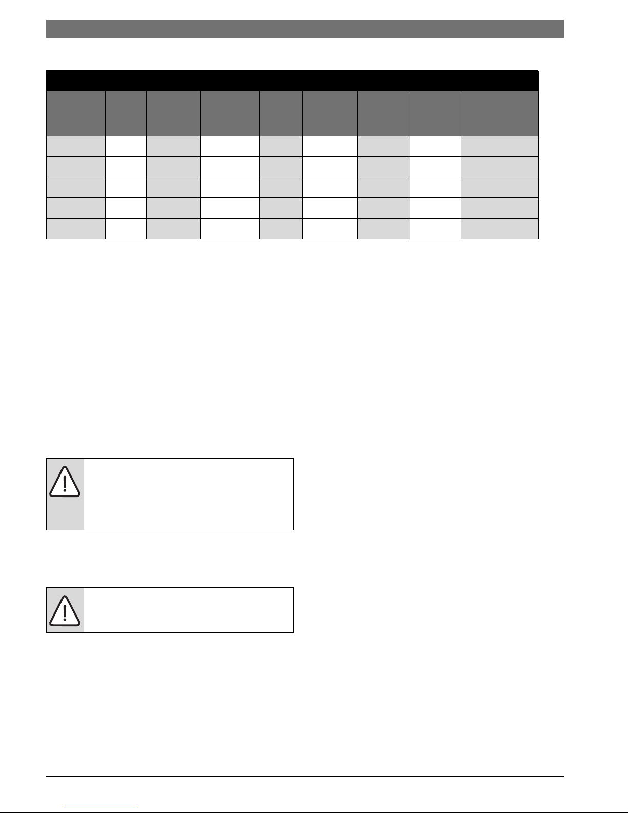
CS/AH Pairing | 3LM Series Heat Pump
S - Straight (AH only)
CS/AH PAIRING
UNIT MODEL
Unit 1 Unit 2
LM024-1CSC
LM036-1CSC
LM048-1CSC
LM060-1CSC
LM070-1CSC
LM024-1AVX
LM036-1AVX
LM048-1AVX
LM060-1AVX
LM070-1AVX
KEY TO SYMBOLS
Warnings
Warnings in this document are identified by
Paired Air Handler
LM024-1AHX
LM036-1AHX
LM048-1AHX
LM060-1AHX
LM070-1AHX
SAFETY WARNINGS
Before performing service or maintenance
operations on the system, turn off main
power to the unit. Electrical shock could
cause personal injury or death.
Installation and servicing of this equipment
can be hazardous due to system pressure
and electrical components. Only trained
and qualified personnel should install,
repair, or service the equipment.
a warning triangle printed against a grey
background. Keywords at the start of the
warning indicate the type and seriousness
of the ensuing risk if measures to prevent
the risk are not taken.
All refrigerant discharged from this unit
must be recovered WITHOUT EXCEPTION.
Technicians must follow industry accepted
guidelines and all local, state, and federal
statutes for the recovery and disposal of
The following keywords are defined and can be
used in this document:
• NOTE indicates a situation that could result in
damage to property or equipment.
• CAUTION indicates a situation that could
result in minor to medium injury.
• WARNING indicates a situation that could
result in sever injury or death.
• DANGER indicates a situation that will result in
severe injury or death.
Important Information
This symbol indicates important information
where there is no risk to property or people.
refrigerants. If a compressor is removed
from this unit, refrigerant circuit oil will
remain in the compressor. To avoid leakage
of compressor oil, refrigerant lines of the
compressor must be sealed after it is
removed.
When working on equipment, always
observe precautions described in the
literature, tags, and labels attached to the
unit. Follow all safety codes. Wear safety
glasses and work gloves. Use a quenching
cloth for brazing, and place a fire
extinguisher close to the work area.
8 733 920 847 (2014/01)Revised 01-14
4 | LM AH Standard Package LM Series Heat Pump AH
1
2
To avoid equipment damage, DO NOT use
these units as a source of heating or cooling
during the construction process. Doing so
may affect the unit’s warranty. The
mechanical components and filters will
quickly become clogged with construction
dirt and debris, which may cause system
damage.
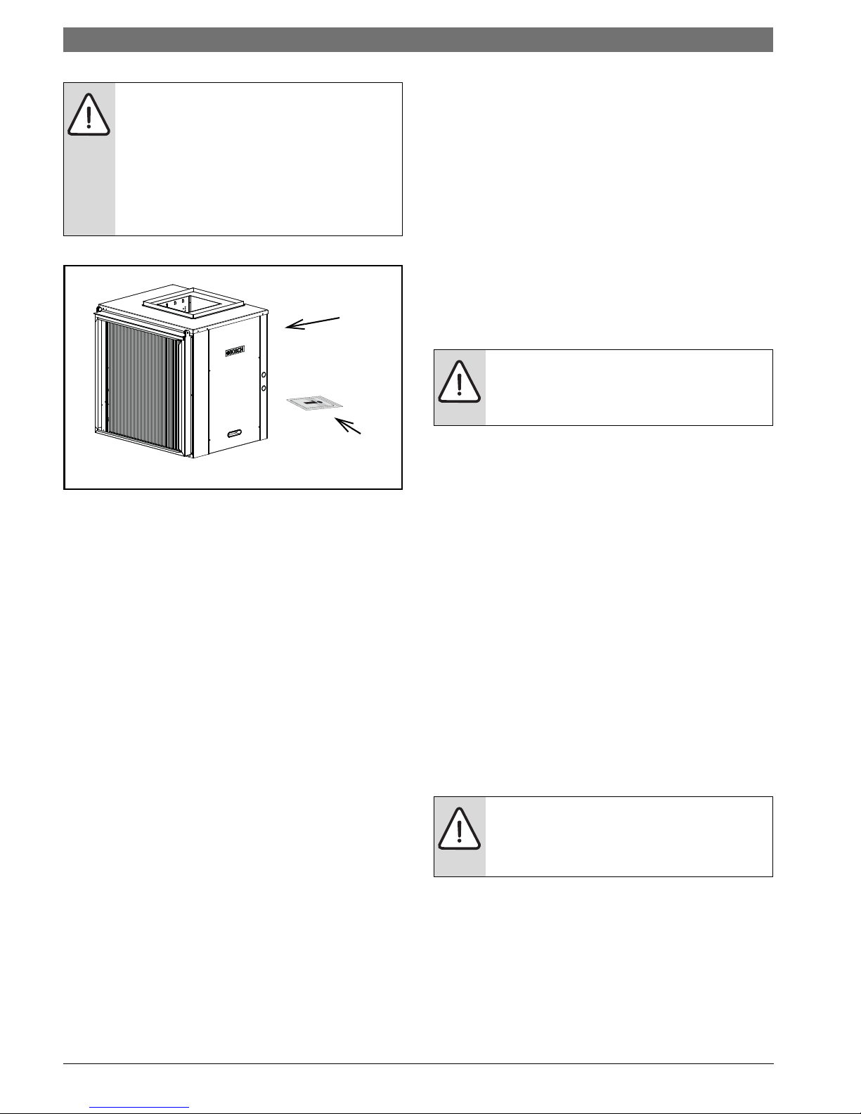
LM AH STANDARD PACKAGE
Figure # 1
[1] LM Series Water-to-Air Heat Pump: Air Handler
[2] Installation and Operation Manual
INITIAL INSPECTION
Be certain to inspect all cartons or crates on each
unit as received at the job site before signing the
freight bill. Verify that all items have been received
and that there are no visible damages; note any
shortages or damages on all copies of the freight
bill. In the event of damage or shortage, remember
that the purchaser is responsible for filing the
necessary claims with the carrier. Concealed
damages not discovered until after removing the
units from the packaging must be reported to the
carrier within 24 hours of receipt.
In the cooling mode, the air coil in the air handler
section serves as an evaporator and the water-torefrigerant heat exchanger serves as a condenser.
In the heating mode, their roles are reversed. The
refrigerant lines connecting the two sections
consist of one line carrying liquid refrigerant and
another carrying refrigerant vapor. The liquid
carrying line will be referred to as the liquid line
while the vapor carrying line will be referred to as
the suction line.
The LM Split AH Water-to-Air Heat Pump units are
performance certified to American Heating and
Refrigeration Institute (AHRI) ISO Standard 13256-
1. All LM Water-to-Air Heat Pumps conform to
UL1995 standard and are certified to CAN/CSA
C22.1 No 236 by Intertek-ETL.
NOTE: This product should not be used for
temporarily heating/cooling during
construction. Doing so may effect the units
warranty.
Several factory installed options are available:
Electric Heat, Air proving sensor and MERV 8&13
filters.
MOVING AND STORAGE
If the equipment is not needed for immediate
installation upon its arrival at the job site, it should
be left in its shipping carton and stored in a clean,
dry area. Units must only be sto r ed or m o v ed in t h e
normal upright position as indicated by the "UP"
arrows on each carton at all times.
SAFETY CONSIDERATIONS
Installation and servicing of this equipment can be
hazardous due to system pressure and electrical
components. Only trained and qualified personnel
should install, repair, or service the equipment.
Untrained personnel can perform basic functions
of maintenance such as cleaning coils and
replacing filters.
GENERAL DESCRIPTION
The LM Split System Water-to-Air Heat Pumps
provide the best combination of performance and
efficiency available. Safety devices are built into
each unit to provide the maximum system
protection possible when properly installed and
maintained.
Split system heat pumps consist of two
independently installed sections allowing for
centralized air distribution while remotely locating
the section containing the compressor and waterto-refrigerant heat exchanger.
WARNING: Before performing service or
maintenance operations on the system, turn
off main power to the unit. Electrical shock
could cause personal injury or death.
When working on equipment, always observe
precautions described in the literature, tags, and
labels attached to the unit. Follow all safety codes.
Wear safety glasses and work gloves. Use a
quenching cloth for brazing, and place a fire
extinguisher close to the work area.
LM Series Heat Pump AH8 733 920 847 (2014/01) Subject to change without prior notice
LOCATION | 5LM Series Heat Pump
AH
CS
LOCATION
To maximize system performance, efficiency and
reliability, and to minimize installation costs, it is
always best to keep the refrigerant lines as short
as possible. Every effort should be made to locate
the air handler and the condensing section as
close as possible to each other.
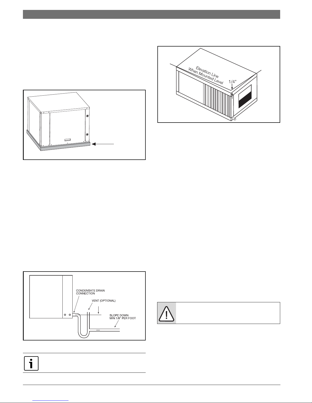
Figure # 2
Air Handler
Locate the air handler unit in an indoor area that
allows easy removal of the filter and access panels,
and has enough room for service personnel to
perform maintenance or repair. Provide sufficient
room to make electrical and duct connections. If
the unit is located in a confined space such as a
closet, provisions must be made for return air to
freely enter the space. On horizontal units, allow
adequate room below the unit for a condensate
drain trap.
The air handler units are not approved for
outdoor installation; therefore, they must be
installed inside the structure being
conditioned. Do not locate in areas that are
subject to freezing.
INSTALLATION
Remove all shipping blocks from the inside
and/or putside of the air handler section
prior to final installation.
NOTE: The installer should comply with all
local codes and regulations which govern
the installation of this type of equipment.
Local codes and regulations take precedent
over any recommendations contained in
these instructions. In lieu of local codes, the
equipment should be installed in
accordance with the recommendations
made by the National electric code, and in
accordance with the recommendations
made by the National Board of Fire
Underwriters.
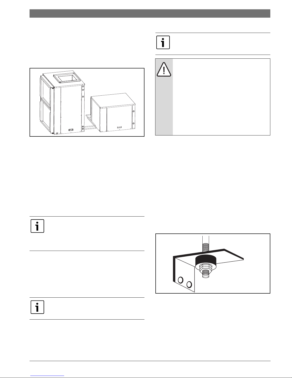
Air Handler
The air handler section may be installed on any
level surface strong enough to support its weight.
When installed in a closet or on a base stand, it
should be mounted on a vibration absorbing pad
slightly larger than the base to minimize vibration
transmission to the building structure.
When installed in an attic or above a drop ceiling,
the installation must conform to all local codes.
When installed in the horizontal position (supply
air at the end or side of the unit), the unit should
be supported on all four corners with threaded
rods attached to the building ceiling rafters and
utilizing the hanger kits (Figure #3). Refer to the
hanging bracket assembly and installation
instructions for details.
Condensing Section
Locate the condensing section in an area that
provides sufficient room to make water and
electrical connections, and allows easy removal of
the access panels, for service personnel to
perform maintenance or repair.
Reference the Condensing Section section of
this manual for detailed installation and
operation.
Figure # 3
Some applications require an attic floor
installation of the air handling unit. In this case the
unit should be set in a full size secondary drain pan
on top of a vibration absorbing mesh. The
secondary drain pan prevents possible condensate
overflow or water leakage damage to the ceiling.
8 733 920 847 (2014/01)Revised 01-14
6 | CONDENSATE DRAIN LM Series Heat Pump AH
Vibration Pad is
recommended
The secondary drain pan is usually placed on a
plywood base isolated from the ceiling joists by
additional layers of vibration absorbing mesh. In
both cases, a 3/4" drain connected to this
secondary pan should be run to an eave at a
location that will be noticeable.(See Figure #4)
If the air handler is located in a crawl space, the
bottom of the unit must be at least 4" above grade
to prevent flooding of the electrical parts due to
heavy rains.
Figure # 4
CONDENSATE DRAIN
The air handler should be pitched approximately 1/
4" towards the drain in both directions, to facilitate
condensate removal. A drain line must be
connected to the air handler and pitched away
from the unit a minimum of 1/8" per foot to allow
the condensate to flow away from the unit. This
connection must be in conformance with local
plumbing codes. A trap must be installed in the
condensate line to insure free condensate flow. A
vertical air vent is sometimes required to avoid air
pockets. (See Figure #5).
The length of the trap depends on the amount of
positive or negative pressure on the drain pan. A
second trap must not be included.
The air handler should be pitched approximately 1/
4" towards the drain in both directions, to facilitate
condensate removal. (See Figure #6)
Figure # 6
DUCT SYSTEM
A supply air outlet collar and return air duct flange
are provided on all units to facilitate duct
connections.
A flexible connector is recommended for supply
and return air duct connections on metal duct
systems. All metal ducting should be insulated
with a minimum of one inch duct insulation to
avoid heat loss or gain and prevent condensate
forming during the cooling operation. Application
of the unit to uninsulated duct work is not
recommended as the unit’s performance will be
adversely affected.
The factory provided air filter must be removed
when using a filter back return air grill.The factory
filter should be left in place on a free return
system.
If the unit will be installed in a new installation
which includes new duct work, the installation
should be designed using current ASHRAE
procedures for duct sizing. If the unit is to be
connected to existing ductwork, a check should be
made to assure that the duct system has the
capacity to handle the air required for the unit
application. If the duct system is too small, larger
ductwork should be installed. Check for existing
leaks and repair.
CAUTION: Do not connect discharge ducts
directly to the blower outlet.
Figure # 5
Units are not internally trapped.
The duct system and all diffusers should be sized
to handle the designed air flow quietly. To
maximize sound attenuation of the unit blower, the
supply and return air plenums should be insulated.
The re s h o u l d b e n o d i r e c t straight air path thru the
return air grille into the heat pump.
LM Series Heat Pump AH8 733 920 847 (2014/01) Subject to change without prior notice
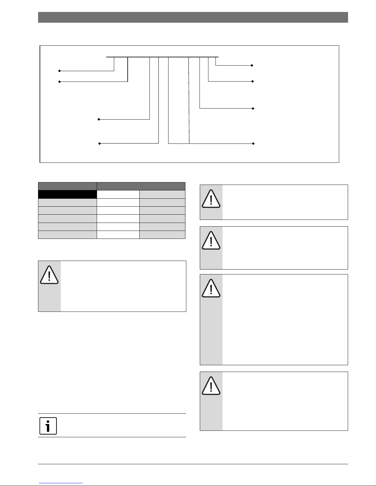
ELECTRICAL | 7LM Series Heat Pump
THERMOSTAT
PACKAGED
HEAT PUMP
Y1
G
C
O
R
Y1
G
B
R
W2
C
O
E
B
W1
W2
Y2
Y2
The return air inlet to the heat pump must have at
least one 90 degree turn away from the space
return air grille. If air noise or excessive air flow are
a problem, the blower speed can be changed to a
lower speed to reduce air flow. (Refer to ECM
motor interface board section in this manual and
Figure #8)
ELECTRICAL
Field wiring must comply with local and national
electric codes. Power to the unit must be within
the operating voltage range indicated on the unit
nameplate or on the performance data sheet. .
CAUTION: Operation of unit on improper
line voltage or with excessive phase
imbalance will be hazardous to the unit,
constitutes abuse and may void the
warranty.
Properly sized fuses or HACR circuit breakers must
be installed for branch circuit protection. See unit
nameplate for maximum fuse or breaker size.
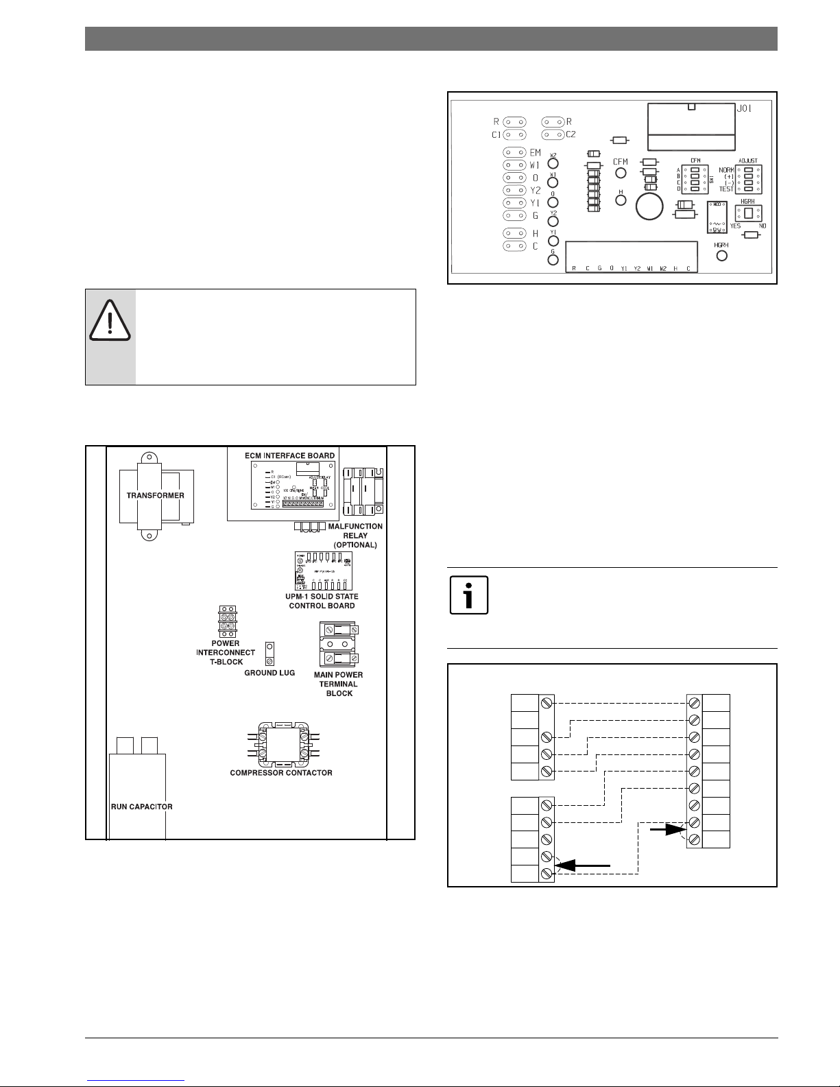
ECM Interface Board
Figure # 8
Electronic Thermostat Installation
Position the thermostat subbase against the wall
so that it is level and the thermostat wires
protrude through the middle of the subbase. Mark
the position of the subbase mounting holes and
drill holes with a 3/16-inch bit. Install supplied
anchors and secure base to the wall. Thermostat
wire must be 8-conductor, 18-AWG wire. Strip the
wires back 1/4-inch (longer strip lengths may
cause shorts) and insert the thermostat wires into
the connector as shown. Tighten the screws to
ensure secure connections. The thermostat has
the same type connectors, requiring the same
wiring. See instructions in the thermostat for
detailed installation and operation information.
Figure # 7 Electrical Component Box Layout
The unit is provided with a concentric knock-out in
the front left corner post for attaching common
trade sizes of conduit, route power supply wiring
through this opening. Always connect the ground
lead to the grounding lug provided in the control
box and power leads to the power supply terminal
block as indicated on the wiring diagram and
Figure #7.
When using a 2-cool, 3-heat thermostat both the
W1 & W2 on the Heat Pump and W2 & EM on
the thermostat must be connected together via
a jumper. (See Figure#9)
Figure # 9
8 733 920 847 (2014/01)Revised 01-14
8 | LM Series Heat Pump AH
Packaged heat pumps are equipped with
detachable Thermostat connectors. These
connectors are located in different locations
based on the blower motor that is installed in the
unit.
For the EON motor, the three detachable
thermostat connectors are located on the ECM
Interface board. See Wiring Harness Drawing
on Pg#24.
Harness wiring can be loose, based on the
options installed for the unit. See the Wiring
Harness Drawing notes for further details.
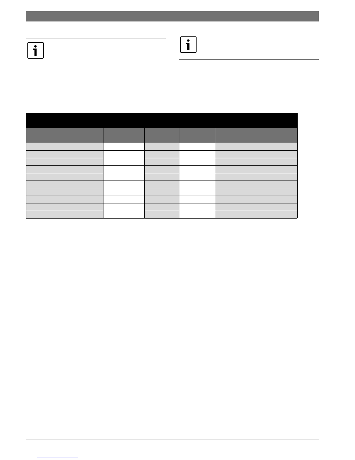
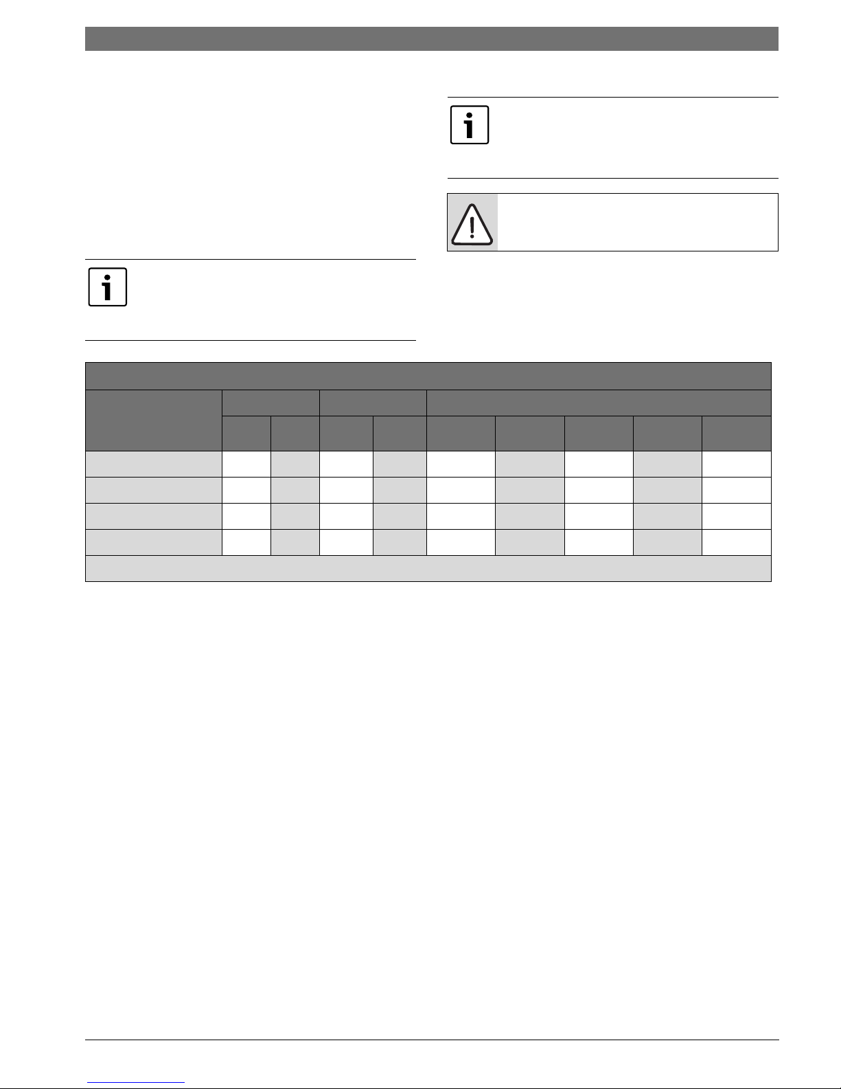
Figure 10: Low Voltage Connection Points
Function
24 VAC Common C CC C
24 VAC Power R R R R
Fan Operation G G- -
Reversing Valve (3) O O O O
Compressor 1st Stage Y1 Y1 Y1 Y1
Compressor 2nd Stage Y2 Y2 Y2 Y2
Condensate Sensor (1) - -CS CS
Alarm Output (From UPM) L /ALR Splice ALR (UPM)
Auxiliary Electric Heat (4) W/W1/W2 W1 - -
Emergency Heat (4) W2/E W2 - -
From
Thermostat
Table Notes:
1)If the condensate overflow sensor option is
utilized connect ‘CS’ at the condensing section to
To Air
Handler
From Air
Handler
To Condensing Section
The thermostat connections and their functions
are as follows:
Y2 Second Stage Compressor Operation
‘CS’ at the air handler. Be sure to ground power
supply.
2)If service LED is utilized connect ‘ALR’ terminal
Y1 First Stage Compressor Operation
GFan
on the UPM board to ‘L’ on the thermostat sub
base. The wiring may be spliced in the air handling
unit. The ‘ALR’ output is hot (R) so check
thermostat instruction manual to ensure
compatibility.
3)‘O’ – reversing valve is energized in the cooling
mode. Fail safe is to heating.
4)Utilized when electric strip heater package
O Reversing Valve (energized in cooling)
W1
EM/W2 Emergency Heat (electric heat only)
NC
Auxiliary Electric Heat
(runs in conjunction with compressor)
Transformer 24 VAC Common
(extra connection)
present.
Thermostat Connections
C1
Transformer 24 VAC Common
(primary connection)
Thermostat wiring is connected to the 10 pin
screw type terminal block on the lower center
portion of the ECM Interface Board. In addition to
R Transformer 24 VAC Hot
HUM Dehumidification Mode
providing a connecting point for thermostat wiring,
the interface board also translates thermostat
inputs into control commands for the variable
speed programmable ECM DC fan motor and
displays an LED indication of operating status.
LM Series Heat Pump AH8 733 920 847 (2014/01) Subject to change without prior notice
| 9LM Series Heat Pump
If the unit is being connected to a thermostat with
a malfunction light, this connection is made at the
unit alarm output.
If the thermostat is provided with a
malfunction light powered off of the
common (C) side of the transformer, a
jumper between “R” and “COM” terminal of
“ALR” contacts must be made.
If the thermostat is provided with a
malfunction light powered off of the hot (R)
side of the transformer, then the thermostat
malfunction light connection should be
connected directly to the (ALR) contact on
the unit’s UPM board.
On the above series units the thermostat wiring
connections are made at the air handling section.
This will allow the capability to utilize both the
condensate overflow switch and the alarm output
options if ordered.
FHP recommends the use of 18 gauge 7 wire solid
copper thermostat conductive cable to wire from
the condensing section terminal strip to the air
handler terminal strip. Typical wiring diagrams are
shown for both the air handler and the condensing
sections.
Just above the connector block is a single red LED
labeled CFM that will blink intermittently when the
unit is running and may flicker when the unit is off.
This LED indicates the air delivery of the blower at
any given time. Each blink of the LED represent
100 CFM of air delivery so if the LED blinks 12
times, pauses, blinks 12 times, etc. the blower is
delivering 1200 CFM. Refer to Figure #11 for
factory programmed air delivery settings for the
LM Series.
To the right of the thermostat connection
block is a green LED labeled dehumidify.
This feature is not utilized on the LM
Series.
Connection point logic is as follows:
To the left of the thermostat connection block are
a row of 2 red and 4 green LED’s. These LED’s
indicate the operating status of the unit. They are
labeled as follows:
EM
W1
RED
RED
O GREEN
Y2
Y1
G
GREEN
GREEN
GREEN
Emergency Heat On
Auxiliary Heat On
Reversing Valve Energized, unit
is in cooling mode
Second Stage Compressor On
First Stage Compressor On
Fan On
8 733 920 847 (2014/01)Revised 01-14
10 | LM Series Heat Pump AH
Figure 11: Motor Profile Air-Flow Table CFM
MODEL
LM024
LM036
LM048
LM060
LM070
FAN
ONLY
450
700
900 925 1500 1500 1500 1700 1275 B
1200 1500 2000 2000 2000 2300 1700 A
1600
Y1
COOL/
HEAT
500 800 800 800 900 700 A
1050 1225 1225 1225 1400 1050 A
1600 2200 2200 2200 2300 1900 A
Y2
COOL/
HEAT
AUX
HEAT
Just above and to the right of the thermostat
connection block are DIP Switches labeled ADJ,
DELAY, HEAT and COOL. The ADJ set of pins are
labeled NORM, (+), (-) and TEST. LM units will all
be set on the NORM position from the factory,
however, airflow can be increased (+) or
decreased (-) by 15% from the pre-programmed
setting by relocating the jumper in this section.
The TEST position is used to verify proper motor
operation. If a motor problem is suspected, move
the ADJ jumper to the TEST position and energize
G on the thermostat connection block.
If the motor ramps up to 100% power, then the
motor itself is functioning normally. Always
remember to replace the jumper to NORM, (+) or () after testing and reset the unit thermostat to
restore normal operation.
NOTE: Do not set the ADJ jumper to the (-)
setting when electric heaters are installed.
Doing so may cause the heaters to cycle on
their thermal overload switches, potentially
shortening the life of the switches.
EMERG
HEAT
PLUS
ADJ
MINUS
ADJ
TAP COOL/
HEAT/DELAY
The other three sets of jumper pins are used to
select the proper program in the ECM motor for
the unit. Refer to Figure #11 for the proper jumper
placement.
NOTE: Always disconnect power before
changing jumper positions on the interface
board and reset the unit afterward.
To the left of the red and green status LED’s is a
row of 1/4” male quick connects. These are used
to pass thermostat inputs on to the rest of the
control circuit. Remember to always turn off unit
power at the circuit breaker before attaching or
disconnecting any wiring from these connections
to avoid accidental short circuits that can damage
unit control components.
LM Series Heat Pump AH8 733 920 847 (2014/01) Subject to change without prior notice
OPTIONS
OPTIONS | 11LM Series Heat Pump
Electric Heat
Internally mounted supplemental electric heat is
available on select models of the LM series.
Electric heating elements can operate along with
In cases where Electric Heat is not available in
a desired configuration but is needed, contact
your distributor for available Duct Mounted
Electric Heat Package.
reverse cycle heating as auxiliary heat or in lieu of
mechanical heating (refrigeration heating) as
emergency backup heat.
Units with internal electric heat must have
2 field power supplies.
Availability matrix, including available nominal kW
capacities is shown in Figure #12:
Internal mounted Electric Heat is only available
on top blow vertical cabinets, end blow
horizontal cabinet or on down blow counterflow
cabinets.
Figure 12: Heater Kit Compatibility Table
KW Btu/h Product Series Compatibility
Heater Model
208V 230V 208V 230V LM024 LM036 LM048 LM060 LM070
HK/HP050-1201 3.6 4.8 12300 16300 x xxxx
HK/HP100-1201 7.2 9.6 24600 32700 x xxxx
HK/HP150-1201 10.8 14.4 36900 49100 xxxx
HK/HP200-1201 14.4 19.2 49200 63400 x xx
Note: x = available
INSTALLATION OF PRESSURE
REGULATING VALVES
Pressure regulating valves are used to increase or
decrease water flow through the heat pump in
response to refrigerant pressure. In some cases
more water may be required in heating than in
cooling, or vice versa. With the Envirosaver heat
pumps these valves are not required. However, if
installed, a pair of valves are required for proper
operation, one valve for cooling (direct acting) and
another valve for heating (indirect acting). A
refrigerant tap is provided in the refrigerant line
located between the reversing valve and the waterto-refrigerant heat exchanger for proper
monitoring of the refrigerant pressures.
The discharge water from the heat pump is not
contaminated in any manner and can be disposed
of in various ways depending on local building
codes (i.e. discharge well, dry well, storm sewer,
drain field, stream or pond, etc.) Most local codes
forbid the use of a sanitary sewer for disposal.
Consult your local building and zoning department
SEQUENCE OF OPERATION
(Figure #13 Wire Schematic)
Cooling Mode
Energizing the “O” terminal energizes the unit
reversing valve in the cooling mode. The fan motor
starts when the “G” terminal is energized. Note
that the fan motor will take 30 seconds to ramp up
to operating speed and will run at fan only air flow
as long as there is no call for compressor or heater
operation.
When “Y1” in the unit (“Y” on the thermostat) is
energized the compressor starts and the unit is
now cooling. Solenoid valves or loop pumps are
brought on in conjunction with the compressor.
When the thermostat is satisfied, the compressor
shuts down and the fan ramps down. If the “G”
terminal is still energized (fan operation is on
“continuous” at the thermostat) the fan will ramp
down to fan only air flow in 30 seconds. If the “G”
terminal is de-energized with “Y1” then the fan
ramps down to off in 30 seconds.
to insure compliance in your area.
8 733 920 847 (2014/01)Revised 01-14
 Loading...