

Bosch LM024, LM060, LM048, LM070, LM036 Installation, Operation And Maintenance Manual
LM Series Heat Pump
LM024 | LM036 | LM048 | LMO60 | LM070
Installation, Operation and Maintenance Manual
8 733 905 315 (2013/9)
2 | LM Series Heat Pump
CONTENTS
Standard package.............................................................. 4
General Description........................................................... 4
Moving and Storage ........................................................... 5
Initial Inspection ............................................................... 5
Location............................................................................ 5
Blower Configurability ....................................................... 5
Return and Discharge Duct Flanges .................................... 6
Mounting Vertical Units ..................................................... 6
Mounting horizontal Units .................................................. 6
Condensate Drain .............................................................. 7
Duct System...................................................................... 7
Piping ............................................................................... 8
Electrical .......................................................................... 8
Safety Devices and the UPM Controller ......................... 10
ECM INTERFACE BOARD- Constant Airflow Motor (Option) ..
13
Dehumidification Method Selector ............................... 14
Troubleshooting ..............................................................24
Electronic Thermostat Installation ....................................29
Operating Temperatures and Pressures ............................ 30
Airflow Tables..................................................................35
Wiring Diagrams ..............................................................37
WIRING HARNESS DRAWINGS ..........................................50
Dimensional Drawings......................................................54
Horizontal - Straight Through .......................................55
Horizontal - Hanging bracket location ............................56
Vertical.....................................................................57
Notes .............................................................................. 58
Constant Torque Motors (ECM) ........................................ 14
Options........................................................................... 15
Hot Gas Reheat (HGRH).............................................. 15
Electric Heat ............................................................. 15
Constant Airflow Motor............................................... 15
Fan Status Switch ...................................................... 15
Pump Status Switch ................................................... 15
DPS Water Flow Proving ............................................. 16
Valve End Switch ....................................................... 16
Pump Relay............................................................... 16
Sequence of Operation .................................................... 16
Cooling Mode ............................................................ 16
Heating Mode............................................................ 16
Application Considerations .............................................. 18
Cooling Tower/Boiler Systems ..................................... 18
Geothermal Systems .................................................. 20
System Checkout ............................................................ 21
Unit Start-up ................................................................... 21
Maintenance ................................................................... 21
Access to Internal Components for Vertical (VT) Units .....22
Unit Check-Out Sheet ...................................................... 23
Customer Data .......................................................... 23
Unit Nameplate Data .................................................. 23
Operating Conditions ................................................. 23
Auxiliary Heat............................................................ 23
LM Series Heat Pump8 733 905 315 (2013/9) Subject to change without prior notice
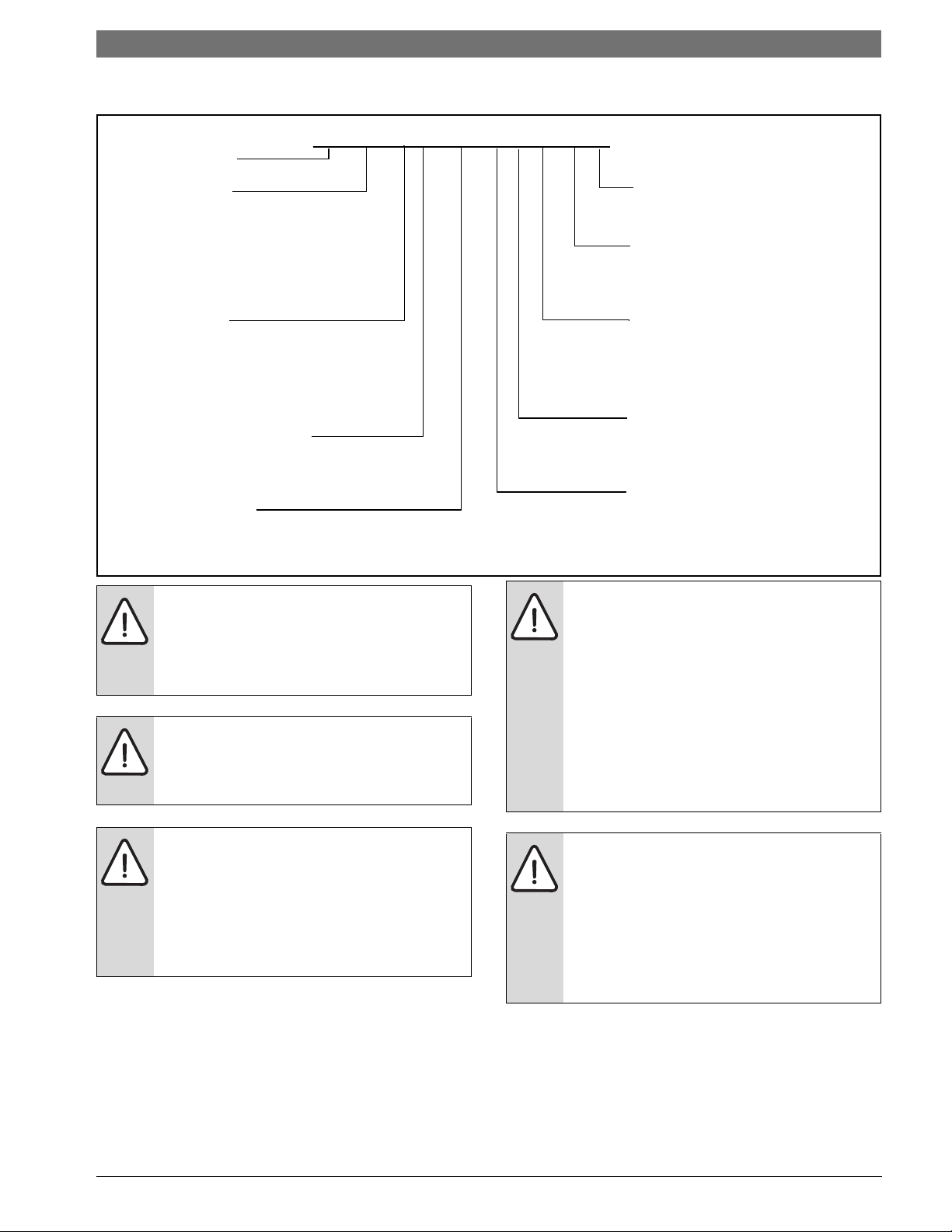
MODEL NOMENCLATURE
LM 024 - 1 VT C - F L T - T A
LM
Size Revision Level
024 A - Current
036
048 Fan/Motor Options
060 A - Constant Airflow ECM
070 T - Constant Torque ECM
Voltage Discharge Air Configuration
1 208-230/60/1 T - Top (VT only)
2 277/60/1 S - Straight (HZ only)
3 208-230/60/3 E - End (HZ only)
4 460/60/3
Return Air Configuration
Cabinet Configuration
L - Left
HZ - Horizontal
R - Right
VT - Vertical
Water Connections
Coax Options
F - Front
C - Copper
N - Cupro-Nickel
| 3LM Series Heat Pump
Installation and servicing of this equipment
can be hazardous due to system pressure
and electrical components. Only trained
and qualified personnel should install,
repair, or service the equipment.
Before performing service or maintenance
operations on the system, turn off main
power to the unit. Electrical shock could
cause personal injury or death.
When working on equipment, always
observe precautions described in the
literature, tags, and labels attached to the
unit. Follow all safety codes. Wear safety
glasses and work gloves. Use a quenching
cloth for brazing, and place a fire
extinguisher close to the work area.
All refrigerant discharged from this unit
must be recovered WITHOUT EXCEPTION.
Technicians must follow industry accepted
guidelines and all local, state, and federal
statutes for the recovery and disposal of
refrigerants. If a compressor is removed
from this unit, refrigerant circuit oil will
remain in the compressor. To avoid leakage
of compressor oil, refrigerant lines of the
compressor must be sealed after it is
removed.
To avoid equipment damage, DO NOT use
these units as a source of heating or cooling
during the construction process. Doing so
may affect the unit’s warranty. The
mechanical components and filters will
quickly become clogged with construction
dirt and debris, which may cause system
damage.
8 733 905 315 (2013/9)Revised 09-13
4 | Standard package LM Series Heat Pump
1
2
3
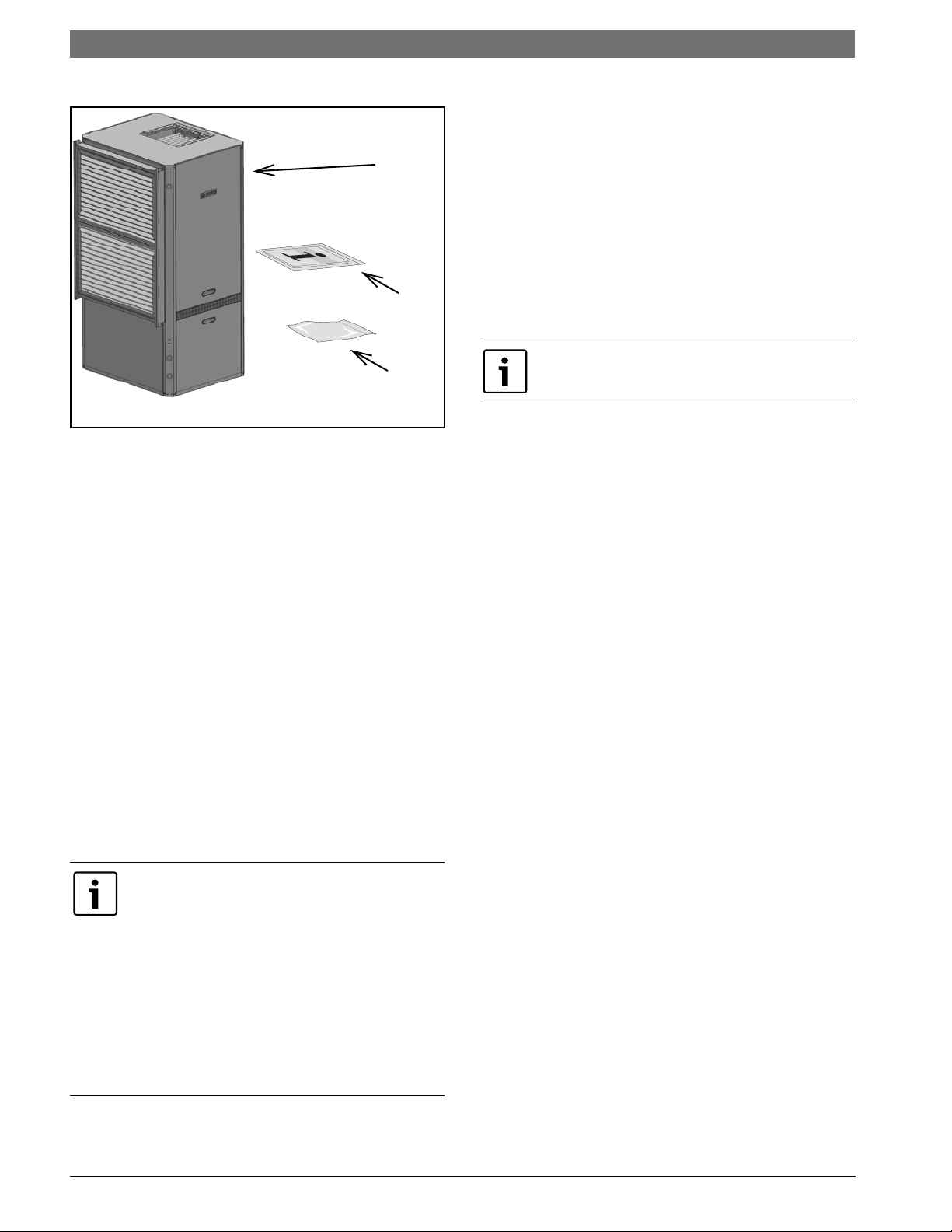
STANDARD PACKAGE
Figure # 1
[1] LM Series Water-to-Air Heat Pump
[2] Installation and Operation Manual
[3] Hanging Bracket Kit (Hz Units Only)
GENERAL DESCRIPTION
LM Series Water-to-Air Heat Pumps provide the
best combination of performance and efficiency
available. All units are performance certified to
American Heating and Refrigeration Institute
(AHRI) ISO Standard 13256-1. All LM Water-to-Air
Heat Pumps conform to UL1995 standard and are
certified to CAN/CSA C22.1 No 236 by IntertekETL.
LM Series Water-to-Air Heat Pumps are available in
Vertical (VT) and Horizontal (HZ) configurations.
VT and HZ units Discharge Air Orientation is Field
Configurable with the purchase of a separate kit.
Several factory installed options are available:
Hot Gas Reheat, Electric Heat, Sound Package,
Smart Start, Constant Airflow Blower Motor, 2” 4sided filter racks, MERV 8 & 13 filters, Differential
Pressure Switch (DPS) Water Flow Proving Switch,
Auxiliary Pump Relay, Air Flow Proving Sensor,
Zone Valve and Internal Water Pump. See Pg#15
for more detail.
Electric Heat is available as a factory installed
option ONLY.
Safety devices are built into each unit to provide
the maximum system protection possible when
properly installed and maintained. Each unit has an
external LED error code display, allowing unit
diagnosis without opening the cabinet.
Basic Horizontal Unit layout and connections are
shown in Figure #2 . For more detail on both the
Vertical and Horizontal units, refer to the
Dimensional Drawings on Pg#55 through Pg#58.
The Water-to-Air Heat Pumps are designed to
operate with entering fluid temperature between
20°F to 90°F in the heating mode and between
30°F to 120°F in the cooling mode.
50° Minimum Entering Water Temperature
(EWT) for well water applications with sufficient
water flow to prevent freezing. Antifreeze
solution is required for all closed loop
applications. Cooling Tower/Boiler and
Geothermal applications should have sufficient
antifreeze solution to protect against extreme
conditions and equipment failure. Frozen water
coils are not covered under warranty. Other
equivalent methods of temperature control are
acceptable.
LM Series Heat Pump8 733 905 315 (2013/9) Subject to change without prior notice
Moving and Storage | 5LM Series Heat Pump
1
2
3
6
7
2
8
5
4
For storage If unit stacking is required,
stack units as follows:
Do not stack 6 ton units!
Vertical units: less than 6 tons, no more
than two high.
Horizontals units: less than 6 tons, no more
than three high.
INITIAL INSPECTION
Be certain to inspect all cartons or crates on each
unit as received at the job site before signing the
freight bill. Verify that all items have been received
and that there are no visible damages; note any
shortages or damages on all copies of the freight
bill. In the event of damage or shortage, remember
that the purchaser is responsible for filing the
necessary claims with the carrier. Concealed
damages not discovered until after removing the
units from the packaging must be reported to the
carrier within 24 hours of receipt.
LOCATION
Locate the unit in an indoor area that allows easy
removal of the filter and access panels, with
enough room for service personnel to perform
maintenance or repair. Provide sufficient room to
make fluid, electrical, and duct connection(s). If
the unit is located in a confined space such as a
closet, provisions must be made for return air to
freely enter the face of unit’s air coil. On horizontal
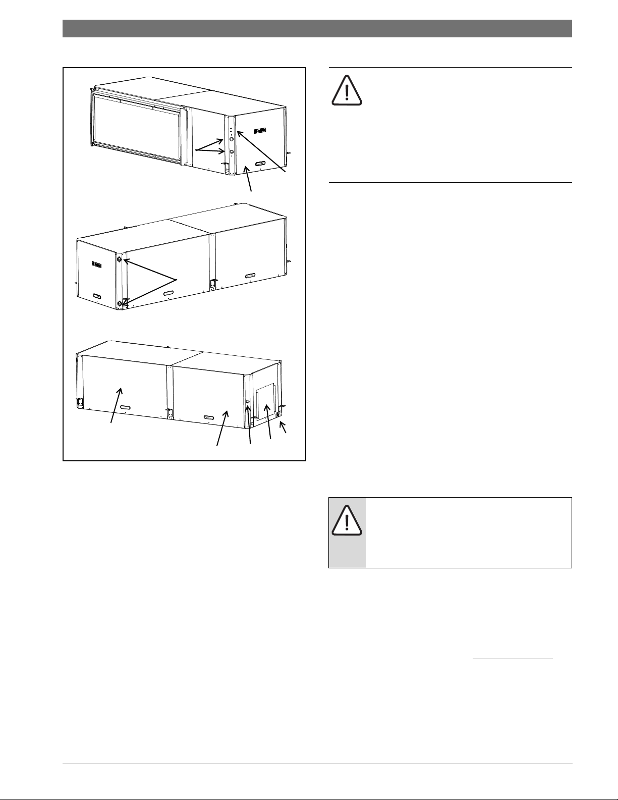
Figure # 2 Left-Hand Unit (Right-Hand Unit is opposite view)
[1] Air handler access panel
[2] Condensing section access panel
[3] Condensate drain connection
[4] Water connection
[5] Electrical connection knockout
[6] Electric Heat electrical connection knockout
(Optional)
[7] Blower outlet (Supply Air)
[8] LED Error Code
MOVING AND STORAGE
If the equipment is not needed for immediate
installation upon its arrival at the job site, it should
be left in its shipping carton and stored in a clean,
dry area. Units must only be stored or moved in the
normal upright position as indicated by the “UP”
arrows on each carton at all times.
units, allow adequate room below the unit for a
condensate drain trap and do not locate the unit
above supply piping.
These units are not approved for outdoor
installation; therefore, they must be
installed inside the structure being
conditioned. Do not locate in areas that are
subject to freezing.
BLOWER CONFIGURABILITY
To change configuration of the LM unit requires
the purchase of a separate Blower panel
Conversion Kit. Please refer to the Spare Parts
List_8733911143 (On website
and the Blower Configurability IM_8733911121.
www.fhp-mfg.com)
8 733 905 315 (2013/9)Revised 09-13
6 | Return and Discharge Duct Flanges LM Series Heat Pump
VIBRATION
PAD FULL SIZE
RETURN AND DISCHARGE DUCT
FLANGES
Return and discharge opening duct flanges are
shipped unfolded. Flanges bend lines are
perforated allowing easy bending using standard
sheet metal pliers or channel locks. (Figure #3)
Bend flanges one at a time, using standard
sheet metal pliers or channel locks
.
Figure # 3
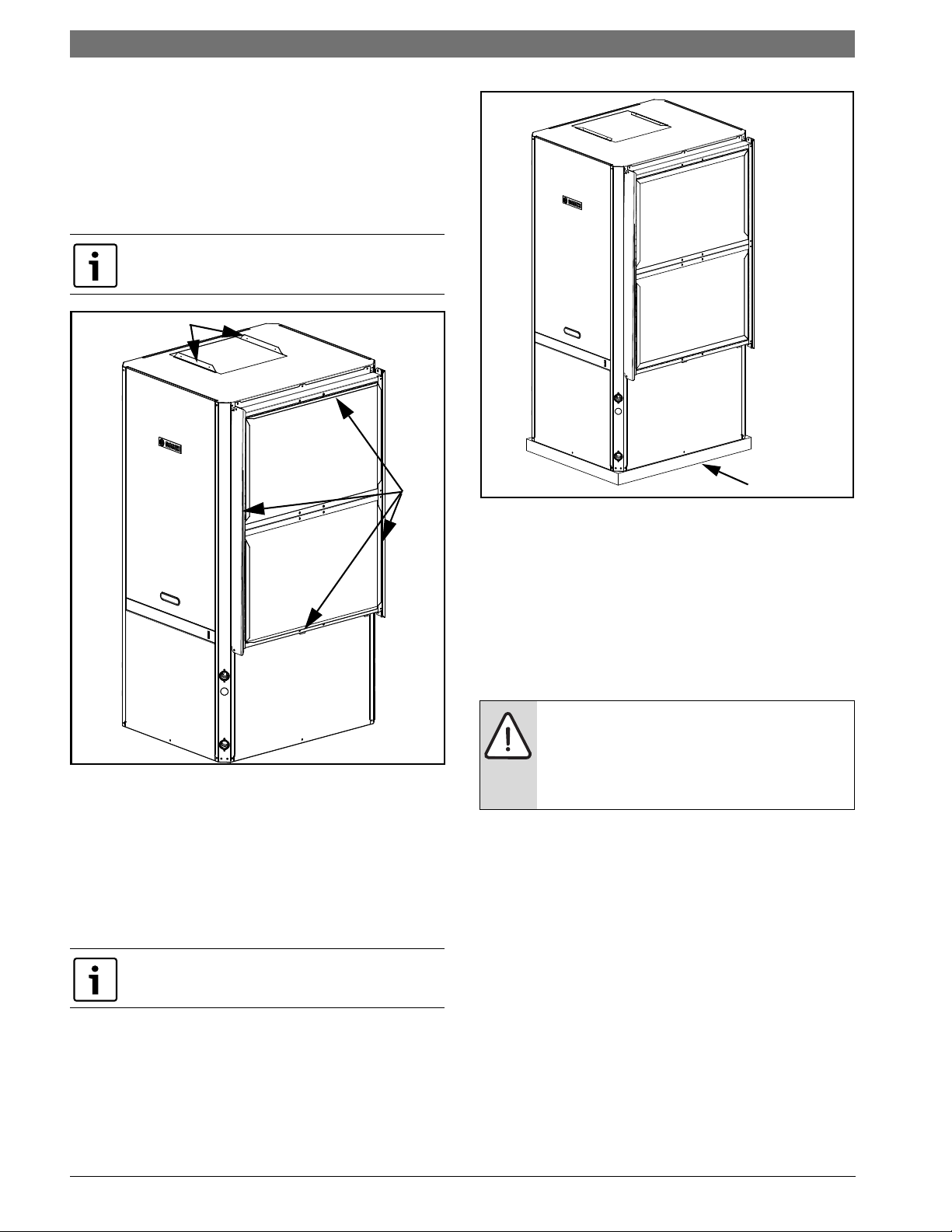
MOUNTING VERTICAL UNITS
Vertical units should be mounted level on a
vibration absorbing pad slightly larger than the
base to minimize vibration transmission to the
building structure. It is not necessary to anchor the
unit to the floor. (Figure #4).
On VT Units Condensate Drain pan is internally
sloped. There is no internal P-Trap.
Figure # 4
MOUNTING HORIZONTAL UNITS
While horizontal units may be installed on any level
surface strong enough to hold their weight, they
are typically suspended above a ceiling by
threaded rods. The manufacturer recommends
these be attached to the unit corners by hanger
bracket kits. The rods must be securely anchored
to the ceiling. Refer to the hanging bracket
assembly and installation instructions for details.
Horizontal units installed above the ceiling
must conform to all local codes. An auxiliary
drain pan if required by code, should be at
least four inches larger than the bottom of
the heat pump.
Plumbing connected to the heat pump must not
come in direct contact with joists, trusses, walls,
etc. Some applications require an attic floor
installation of the horizontal unit. In this case the
unit should be set in a full size secondary drain pan
on top of a vibration absorbing mesh.
The Secondary drain pan prevents possible
condensate overflow or water leakage damage to
the ceiling.
The secondary drain pan is usually placed on a
plywood base isolated from the ceiling joists by
additional layers of vibration absorbing mesh. In
both cases, a 3/4”drain connected to this
secondary pan should be run to an eave at a
location that will be noticeable.
LM Series Heat Pump8 733 905 315 (2013/9) Subject to change without prior notice
Condensate Drain | 7LM Series Heat Pump
If the unit is located in a crawl space, the bottom
of the unit must be at least 4” above grade to
prevent flooding of the electrical parts during
heavy rains.
Horizontal (HZ) units must be installed
pitched toward the Condensate Drain
Connection 1/8” per foot.
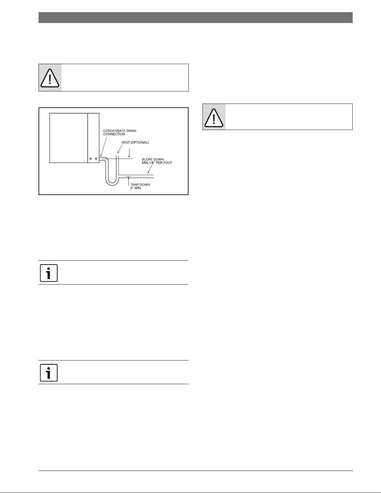
CONDENSATE DRAIN
Figure # 5
A drain line must be connected to the heat pump
and pitched away from the unit a minimum of 1/8”
per foot to allow the condensate to flow away from
the unit.
This c onne c tion m ust b e in conformance with local
plumbing codes. A trap must be installed in the
condensate line to insure free condensate flow.
HZ Heat Pump Drain Pan is not internally
sloped.
A vertical air vent is sometimes required to avoid
air pockets. The length of the trap depends on the
amount of positive or negative pressure on the
drain pan. A second trap must not be included.
DUCT SYSTEM
A supply air outlet collar and return air duct flange
are provided on all units to facilitate duct
connections.
A flexible connector is recommended for supply
and return air duct connections on metal duct
systems. All metal ducting should be insulated
with a minimum of one inch duct insulation to
avoid heat loss or gain and prevent condensate
forming during the cooling operation. Application
of the unit to uninsulated duct work is not
recommended as the unit’s performance will be
adversely affected.
Do not connect discharge ducts directly to
the blower outlet.
The factory provided air filter must be removed
when using a filter back return air grill. The factory
filter should be left in place on a free return
system.
If the unit will be installed in a new installation
which includes new duct work, the installation
should be designed using current ASHRAE
procedures for duct sizing. If the unit is to be
connected to existing duct work, a check should
be made to assure that the duct system has the
capacity to handle the air required for the unit
application. If the duct system is too small, larger
duct work should be installed. Check for existing
leaks and repair.
The duct system and all diffusers should be sized
to handle the designed air flow quietly. To
maximize sound attenuation of the unit blower, the
supply and return air plenums should be insulated.
The r e should be no direct s t r aight air path thr u t he
return air grille into the heat pump. The return air
inlet to the heat pump must have at least one 90
degree turn away from the space return air grille. If
air noise or excessive air flow are a problem, the
blower speed can be changed to a lower speed to
reduce air flow.
Supply air duct and return air duct flanges are
shipped unfolded with unit.
Fo l d t he d uc t f la n ge ou tw ards along the perforated
line. Refer to unit Dimensional Drawings for
physical dimensions of the collar and flange.
(Pg#55 through Pg#58)
8 733 905 315 (2013/9)Revised 09-13
8 | Piping LM Series Heat Pump
PIPING
Supply and return piping must be as large as the
unit connections on the heat pump (larger on long
runs).
Never use flexible hoses of a smaller inside
diameter than that of the fluid connections
on the unit.
LM units are supplied with either a copper or
optional cupro-nickel condenser. Copper is
adequate for ground water that is not high in
mineral content.
Proper testing is recommended to assure the
well water quality is suitable for use with water
source equipment.
In conditions anticipating moderate scale
formation or in brackish water a cupro-nickel heat
exchanger is recommended.
Both the supply and discharge water lines will
sweat if subjected to low water temperature.
These lines should be insulated to prevent damage
from condensation. All manual flow valves used in
the system must be ball valves. Globe and gate
valves must not be used due to high pressure drop
and poor throttling characteristics.
Never exceed the recommended water flow
rates, as serious damage or erosion of the
water-to-refrigerant heat exchanger could
occur.
Always check carefully for water leaks and repair
appropriately. Units are equipped with female pipe
thread fittings. Consult Unit Dimensional
Drawings. (Pg#55 through Pg#58)
Teflon tape sealer should be used when
connecting water piping connections to the units
to insure against leaks and possible heat
exchanger fouling.
Do not overtighten the connections.
ELECTRICAL
Refer to electrical component box layout.
(Figures #6-8)
Field wiring must comply with local and
national electric codes.
Power to the unit must be within the
operating voltage range indicated on
the unit nameplate or on the
performance data sheet.
Operation of unit on improper line
voltage or with excessive phase
imbalance will be hazardous to the unit,
constitutes abuse and may void the
warranty.
Properly sized fuses or HACR circuit breakers must
be installed for branch circuit protection. See unit
nameplate for maximum fuse or breaker size.
The unit is provided with a concentric knock-out
for attaching common trade sizes of conduit, route
power supply wiring through this opening.
Always connect the ground lead to the grounding
lug provided in the control box and power leads to
the line side of compressor contactor as indicated
on the wiring diagram (Figures#25 through #31,
Pg#38 through Pg#47).
Units supplied with internal electric heat require
two (2) separate power supplies:
1) Unit compressor
2) Electric Heat, Blower Motor and Control
Circuit.
--------------------------------------------------------------
Refer to the ELECTRIC HEATER PACKAGE
OPTION section and Pg#38 through Pg#47 for
wiring diagrams. See data plate for minimum
circuit ampacities and maximum fuse/breaker
sizing.
Flexible hoses should be used between the unit
and the rigid system to avoid possible vibration.
Ball valves should be installed in the supply and
return lines for unit isolation and unit water flow
balancing.
LM Series Heat Pump8 733 905 315 (2013/9) Subject to change without prior notice
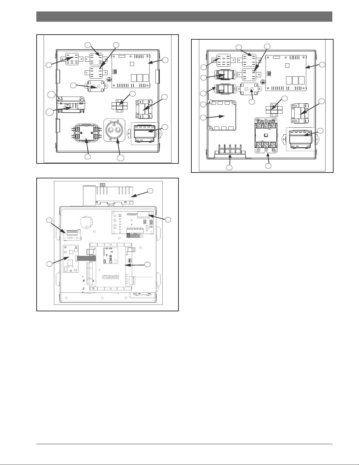
Figure # 6 - Single Phase Unit
4
5
16
3
2
21
6
7
8
9
1
10
18
20
11
19
17
4
5
14
13
3
12
15
8
9
7
6
2
21
1
Electrical | 9LM Series Heat Pump
Figure # 8 Three Phase Unit
[1] Compressor contactor
[2] Emergency Relay (Option)
[3] Second Stage Relay
[4] Hot Gas Reheat Relay (Option)
[5] Cooling Relay
[6] Unit Protection Module (UPM)
[7] Terminal block Low-Voltage
[8] Auxiliary Relay (Option)
[9] Transformer
[10] Capacitor
[11] ECM Interface Board(Option, mounts on E-
Box cover)
[12] Phase Monitor
[13] Fan Status Switch (Option)
[14] Pump Status Switch (Option)
Figure # 7 EBox Cover
[15] Terminal Block 460V Units (Option)
[16] Comfort Alert Module (Option)
[17] DDC (Option)
[18] LonWorks Card (Option)
[19] Input Expansion Module (Option)
[20] Smart Start Assist (Option)
[21] Ground Lug
8 733 905 315 (2013/9)Revised 09-13
10 | Electrical LM Series Heat Pump
1
2
3
4
5
6
7
9
10
11
1213
17
14
15
16
8
Safety Devices and the UPM Controller
If the thermostat is provided with a malfunction
light powered off of the hot (R) side of the
transformer, then the thermostat malfunction
light connection should be connected directly to
the (ALR) contact on the unit’s UPM board.
Each unit is factory provided with a Unit Protection
Module (UPM) that controls the compressor
operation and monitors the safety controls that
protect the unit.
Safety controls include the following:
• High pressure switch located in the refrigerant
discharge line and wired across the HPC
terminals on the UPM
• Low pressure switch located in the unit
refrigerant suction line and wired across
terminals LPC1 and LPC2 on the UPM.
UPM Board Dry Contacts are Normally Open
(NO)
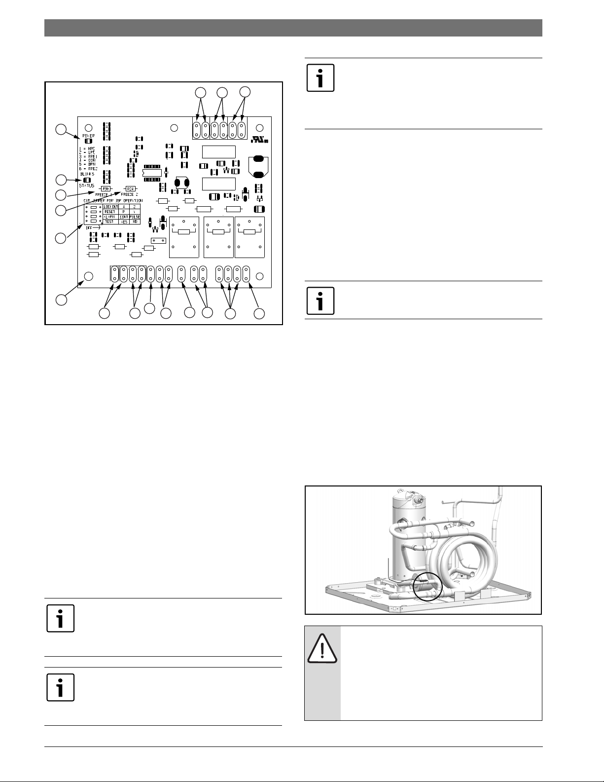
Figure # 9
[1] Board Power Indicator
[2] UPM Status LED Indicator
[3] Water Coil Freeze Protection Temperature
Selection [R30]
[4] Air Coil Freeze Protection Temperature
Selection
[5] UPM Board Settings
[6] Water Coil Freeze Connection
[7] Air Coil Freeze Connection
[8] LED Status-Diagnostic Connection
[9] 24VAC Power Input
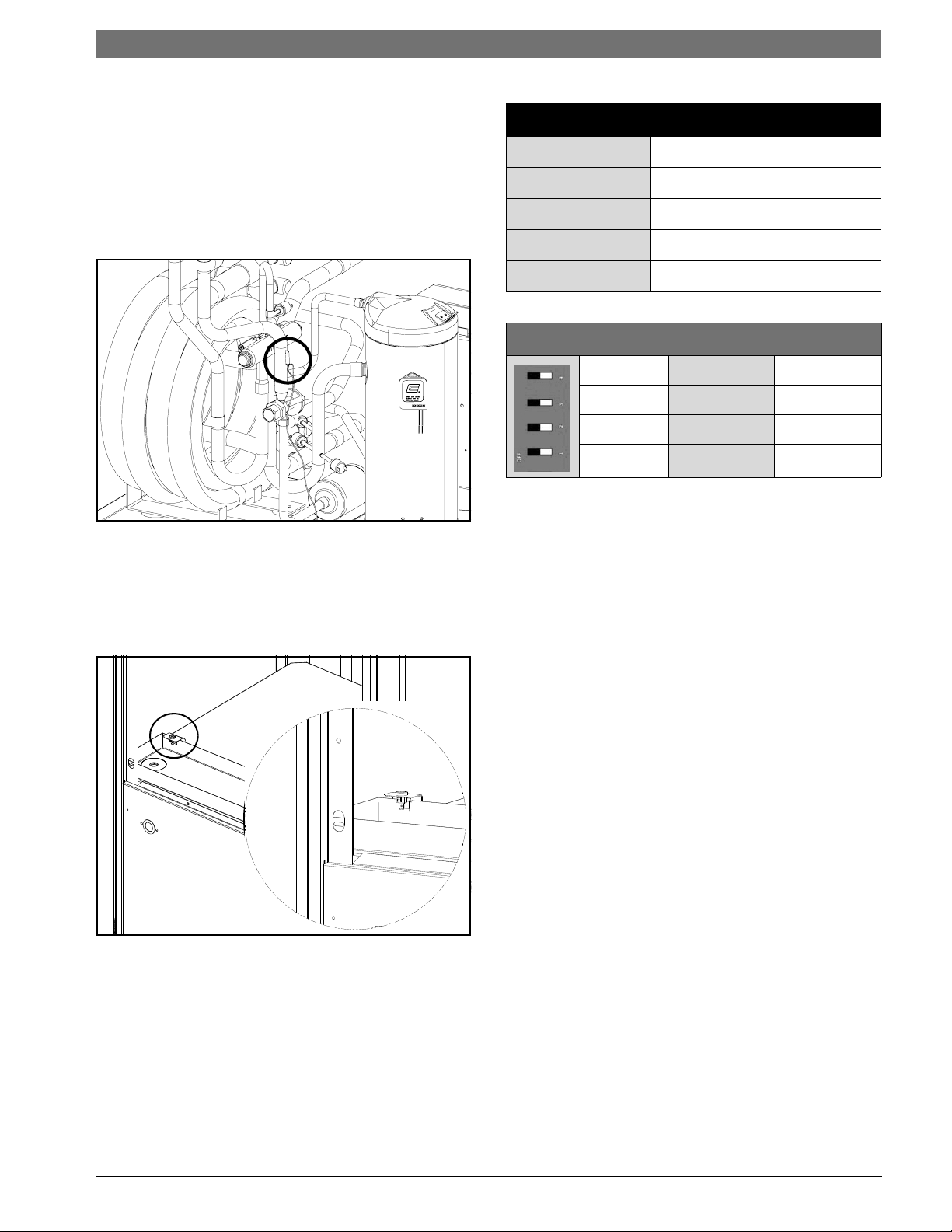
• Water side freeze protection sensor, mounted
close to condensing water coil, monitors
refrigerant temperature between condensing
water coil and thermal expansion valve. If
temperature drops below or remains at freeze
limit trip for 30 seconds, the controller will
shut down the compressor and enter into a
soft lockout condition. The default freeze limit
trip is 30°F, however this can be changed to
15°F by cutting the R30 or Freeze1 resistor
located on top of DIP switch SW1. Refer to
Figure #9, item [3] for resistor location. (Refer
to Figure #10 for sensor location)
[10] Compressor Contact Output
[11] High Pressure Switch Connection
[12] Call for Compressor Y1
[13] Low Pressure Switch Connection
[14] 24VAC Power Common
[15] Condensate Overflow Sensor
[16] Dry Contact
[17] UPM Ground Standoff
If the unit is being connected to a thermostat
with a malfunction light, this connection is made
at the unit malfunction output or relay. Refer to
Figure #9.
If the thermostat is provided with a malfunction
light powered off of the common (C) side of the
transformer, a jumper between “R” and “COM”
terminal of “ALR” contacts must be made.
Figure # 10
If unit is employing a fresh water system (no
anti-freeze protection), it is extremely
important to have the Freeze1 R30 resistor
set to 30°F in order to shut down the unit at
the appropriate leaving water temperature
and protect your heat pump from freezing if
a freeze sensor is included.
LM Series Heat Pump8 733 905 315 (2013/9) Subject to change without prior notice
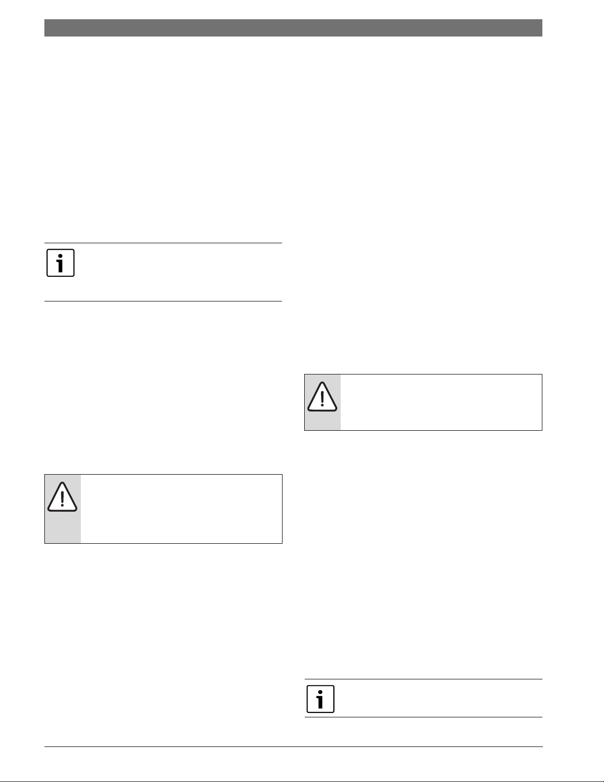
• Evaporator freeze protection sensor, mounted
between the thermal expansion device and the
evaporator, monitors refrigerant temperature
between the evaporator coil and thermal
expansion valve. If temperature drops below or
remains at freeze limit trip for 30 seconds, the
controller will shut down the compressor and
enter into a soft lockout condition. The default
freeze limit trip is 30°F. (Figure#11)
Electrical | 11LM Series Heat Pump
UPM Board Factory Default Settings
TEMP
LOCKOUT
RESET
ALARM
TEST
30°F
2
Y
PULSE
NO
UPM DIP SWITCH DEFAULT POSITION
lockout 42
Figure # 11
• The condensate overflow protection sensor is
located in the drain pan of the unit and
connected to the ‘COND’ terminal on the UPM
board. (Figure #)
Figure # 12
reset
alarm
test
RY
Cont pulse
yes no
The UPM Board includes the following features:
• ANTI-SHORT CYCLE TIMER:
break timer to prevent compressor short cycling.
5 minute delay on
• RANDOM START: Each controller has an unique
random start delay ranging from 270 to 300 seconds
on initial power up to reduce the chance of multiple
unit simultaneously starting at the same time after
power up or after a power interruption, thus
avoiding creating large electrical spike.
• LOW PRESSURE BYPASS TIMER: If the
compressor is running and the low pressure switch
opens, the controller will keep the compressor ON
for 120 seconds. If, after 120 seconds the low
pressure switch remains open, the controllers will
shut down the compressor and enter a soft lockout.
The compressor will not be energized until the low
pressure switch closes and the anti-short cycle time
delay expires. If the low pressure switch opens 2-4
times in 1 hour, the unit will enter a hard lockout. In
order to exit hard lockout power to the unit would
need to be reset.
• BROWNOUT/SURGE/POWER
INTERRUPTION PROTECTION:
protection in the UPM board will shut does the
compressor if the incoming power falls below 18
VAC. The compressor will remain OFF until the
voltage is above 18 VAC and ANTI-SHORT CYCLE
TIMER (300 seconds) times out. The unit will not go
into a hard lockout.
The brownout
8 733 905 315 (2013/9)Revised 09-13
12 | Electrical LM Series Heat Pump
• MALFUNCTION OUTPUT: Alarm output is
Normally Open (NO) dry contact.
If pulse is
selected the alarm output will be pulsed. The
fault output will depend on the dip switch
setting for "ALARM". If it is set to "CONST", a
constant signal will be produced to indicate a
fault has occurred and the unit requires
inspection to determine the type of fault. If it is
set to "PULSE", a pulse signal is produced and
a fault code is detected by a remote device
indicating the fault. See LED Fault Indication
below for blink code explanation. The remote
device must have a malfunction detection
capability when the UPM board is set to
"PULSE".
If 24 VAC output is needed R must be wired to
ALR-COM terminal; 24 VAC will be available o
the ALR-OUT terminal when the unit is in the
alarm condition.
• LED ANNUNCIATOR:
quick visual indication of whether or not a heat
pump is energized and if it has locked out on a fault.
The LED kit is mounted to the electrical corner post
of the heat pump and employs high intensity LED’s
for better visibility. The LED kit will exactly mirror
the LED blink codes on the UPM board (refer to the
blink co
de table in the UPM sequence of
This LED kit provides a
operation).
• TEST DIP SWITCH:
to reduce all time delays settings to 10 seconds
during troubleshooting or verification of unit
operation.
Operation of unit in test mode can lead to
accelerated wear and premature failure of
components. The "TEST" switch must be set
back to "NO" after troubleshooting/
servicing.
A test dip switch is provided
• FREEZE SENSOR: The default setting for the
freeze limit trip is 30°F (sensor number 1); however
this can be changed to 15°F by cutting the R30
resistor located on top of the DIP switch SW1.
default setting for the freeze limit trip is 30°F
(sensor number 1); however this can be
changed to 15°F by cutting the R24 resistor
located on top of the DIP switch SW1. Since
freeze sensor 2 is dedicated to monitor the
evaporator coil it is recommended to leave the
factory default setting on the board. The UPM
controller will constantly monitor the
refrigerant temperature with the sensor
mounted close to the condensing water coil
The
between the thermal expansion valve and
water coil. If temperature drops below or
remains at the freeze limit trip for 30 seconds,
the controller will shut the compressor down
and enter into a soft lockout condition. Both
the status LED and the Alarm contact will be
active. The LED will flash (three (3) times) the
code associated with this alarm condition. If
this alarm occurs 2 times (or 4 if Dip switch is
set to 4) within an hour the UPM controller will
enter into a hard lockout condition. It will
constantly monitor the refrigerant temperature
with the sensor mounted close to the
evaporator between the thermal expansion
valve and evaporator coil as shown in Figure
#5. If temperature drops below or remains at
the freeze limit trip for 30 seconds, the
controller will shut the compressor down and
enter into a soft lockout condition. Both the
status LED and the Alarm contact will be
active. The LED will flash (three (6) times) the
code associated with this alarm condition. If
this alarm occurs 2 times (or 4 if Dip switch is
set to 4) within an hour the controller will enter
into a hard lockout condition.
Refer to page #10 for more information.
Freeze sensor will not guard against loss of
water. Flow switch is recommended to
prevent unit from running, if water flow is
lost or reduced.
• INTELLIGENT RESET: If a fault condition is
initiated, the 5 minute delay on break time
period is initiated and the unit will restart after
these delays expire. During this period the
fault LED will indicate the cause of the fault. If
the fault condition still exists or occurs 2 or 4
times (depending on 2 or 4 setting for Lockout
dip switch) before 60 minutes, the unit will go
into a hard lockout and requires a manual
lockout reset. A single condensate overflow
fault will cause the unit to go into a hard
lockout immediately, and will require a manual
lockout reset.
• LOCKOUT RESET: A hard lockout can be reset
by turning the unit thermostat off and then
back on when the “RESET” dip switch is set to
“Y” or by shutting off unit power at the circuit
breaker when the “RESET” dip switch is set to
“R”.
The blower motor will remain active during a
lockout condition.
LM Series Heat Pump8 733 905 315 (2013/9) Subject to change without prior notice
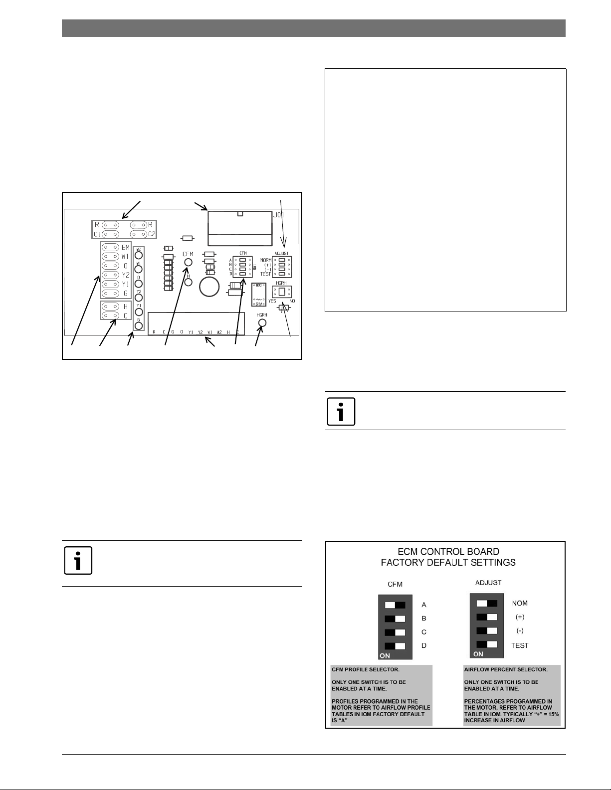
ECM INTERFACE BOARD- Constant
10
1
27
8
9
546
11
3
Airflow Motor (Option)
Refer to Figure #9, item [12] for ECM interface
board location. In addition to providing a
connecting point for thermostat wiring, the
interface board also translates thermostat inputs
into control commands for the Electronic
Commutated Motor (ECM) DC fan motor and
provides thermostat signlas to unit’s UPM board.
The thermostat connections and their functions
are as follows:
Electrical | 13LM Series Heat Pump
Thermostat Outputs
Y1 First Stage Compressor Operation
Y2 Second Stage Compressor Operation
GFan
O Reversing Valve (energized in cooling)
W1 Auxiliary Electric Heat (runs in conjunction
with compressor)
EM/W2 Emergency Heat (electric heat only)
NC Transformer 24 VAC Common (extra
connection)
C1 Transformer 24 VAC Common (primary
connection)
R Transformer 24 VAC Hot
H Dehumidification Mode
Figure # 13
[1] Motor harness plug
[2] Blower CFM adjustment
[3] Motor settings
[4] Dehumidification indication
[5] Thermostat digital contact inputs
[6] CFM count indicator
[7] Thermostat input status indication
[8] Reheat digital outputs
[9] Thermostat outputs
[10] 24 VAC
[11] Dehumidification method selector
CFM LED indication is an approximation. Utilize
conventional Test and Balance equipment for
accurate airflow measurement.
• CFM count indicator (See Figure #13, item [6])
blinks to indicate approximate airflow in CFM
and may flicker when unit is off.
• Each blink of the LED represent approximately
100 CFM of air delivery so if the LED blinks 12
times, pauses, blinks 12 times, etc. the blower
is delivering approximately 1200 CFM.
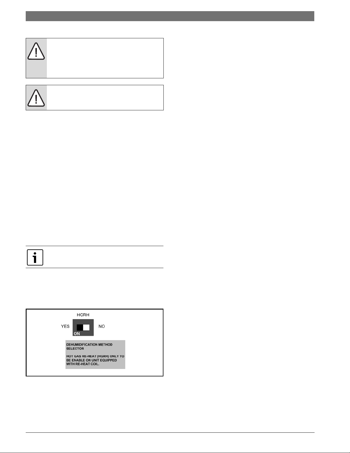
Airflow Selector
The airflow selector (Figure #13, items [2] & [3])
allows airflow adjustment to meet application
requirements and to ease troubleshooting.
Only one switch can be enabled at a time. Refer
to Figure #22 for each airflow setting.
• CFM Selector (FIg #13, Item [2]) must remain
with only “A” being enabled.
• ADJUST Selector can be adjusted to NOM, (+),
(-), or TEST. NOM, (+) and (-) can be adjusted
as needed by application. TEST is used for
troubleshooting to override unit airflow to
100%.
8 733 905 315 (2013/9)Revised 09-13
14 | Constant Torque Motors (ECM) LM Series Heat Pump
To the left of the red and green status LED’s is a
Do not set the ADJ DIP switch to the (-)
setting when electric heaters are installed.
Doing so may cause the heaters to cycle on
their thermal overload switches, potentially
shortening the life of the switches.
row of 1/4” male quick connects. These are used
to pass thermostat inputs on to the rest of the
control circuit. Remember to always turn off unit
power at the circuit breaker before attaching or
disconnecting any wiring from these connections
to avoid accidental short circuits that can damage
unit control components.
Always disconnect power before changing
DIP Switch position on the interface board
and reset the unit afterward.
CONSTANT TORQUE MOTORS (ECM)
For installations where the efficiency of an
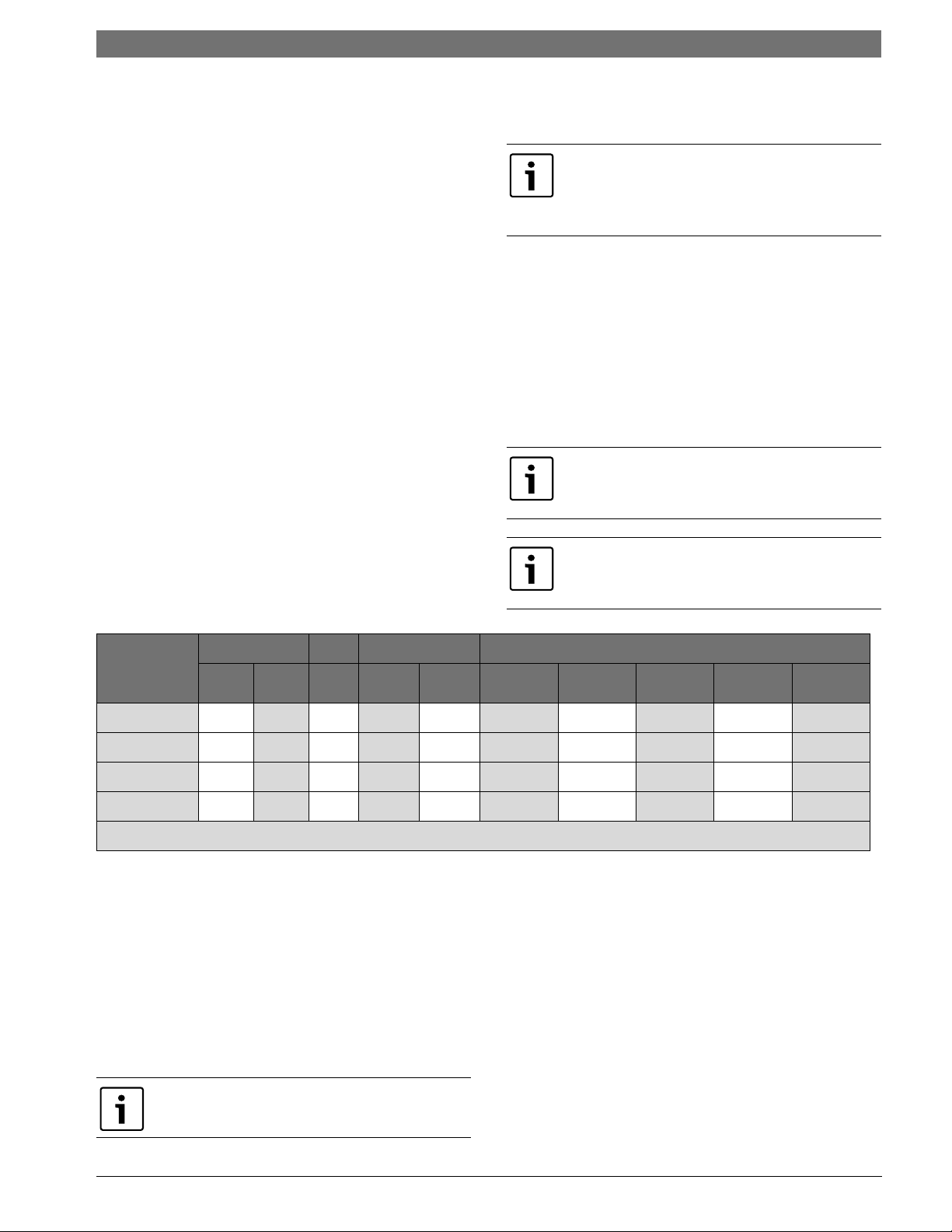
Dehumidification Method Selector
Dehumidification method selector (Figure #13,
item [11]) is used to select between the following
two methods:
1. 1) Units equipped with optional Hot Gas
Reheat, on dehumidification call (the “H”
terminal on the thermostat is energized) the
reheat outputs will energize the hot gas reheat
valve in the circuit and the heat pump will start
in dehumidification mode.
Dehumidificationselector (Figure #13, item
[11]) should be selected to ‘YES’.
2. Units without optional Hot Gas Reheat, on
dehumidification call, the heat pump fan will
operate at a lower speed to increase
dehumidification while cooling.
Dehumidification selector ((Figure #13, item
[11]) should be selected to ‘NO’.
In this mode, the heat pump will only dehumidify
the space when it is running in cooling mode.
electronically commutated brushless DC motor
(ECM) motor is required, but the features of a
constant airflow motor are not required, the LM
series comes standard with the constant torque
ECM motor option. These motors feature up to
90% thermal efficiency combined with a flatter fan
curve than a PSC motor and simple operation.
These motors are provided with 5 speed taps to
allow for a wide range of air flow and external
static options.
To change a speed tap follow the instructions
below:
1. Disconnect power to the heat pump.
2. Remove the blower access panel.
3. Remove the speed tap wire from the terminal it
is currently connected to and connect it to the
terminal desired.
Refer to the constant torque motor performance
tables for heat pump blower performance with the
constant torque motor option. (Pg#35)
Dehumidification indicator LED (Figure #13,
item [4]) will energize when dehumidification
call is present.
LM Series Heat Pump8 733 905 315 (2013/9) Subject to change without prior notice
Options | 15LM Series Heat Pump
OPTIONS
Number of factory installed options are available
on LM Series of Heat Pumps. The following details
the purpose, function and components of each
option.
Hot Gas Reheat (HGRH)
Hot gas reheat is an active dehumidification option
available on the LM series that cools and
dehumidifies return air, and then reheats it back to
approximately entering dry bulb temperature using
waste compressor heat. In this way, a unit with Hot
Gas Reheat can efficiently remove humidity from
the return air without altering the sensible
temperature of the space.
The reheat option consists of a refrigerant to air
heat exchanger (reheat coil) mounted down
stream of the evaporator coil. When there is a
signal for dehumidification AND the sensible space
temperature is satisfied, the unit will operate in
reheat mode. In reheat mode the heat pump will
operate at full load cooling and will divert
discharge gas from the compressor to the reheat
coil, effectively cooling and dehumidifying the air
and then reheating it back to a temperature close
to the entering dry bulb temperature. If there is a
call for sensible cooling while the unit is operating
in the reheat mode, then the unit will revert to
cooling until the sensible demand is satisfied.
Heat pumps with hot Gas Reheat need to be
connected to a humidistat along with a
traditional thermostat or a combination
thermostat/humidistat.
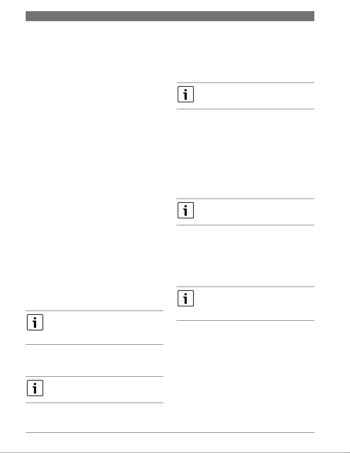
Electric Heat
Internally mounted supplemental electric heat is
available on select models of the LM series.
Electric heating elements can operate along with
reverse cycle heating as auxiliary heat or in lieu of
reverse cycle heating (refrigeration heating) as
emergency backup heat.
Availability matrix, including available nominal kW
capacities is shown below:
Internal mounted Electric Heat is only available
on top blow vertical cabinets, end blow
horizontal cabinet .
Internal electric heat cannot be provided with
hot gas reheat. Units with internal electric heat
must have 2 field power supplies.
KW Stgs Btu/h Product Series Compatibility
Heater
Model
Kw05- 3.6 4.8 1 12300 16300 xxxxx
Kw10- 7.2 9.6 2 24600 32700 x xxx
Kw15 10.8 14.4 2 36900 49100 xxx
Kw20 14.4 19.2 2 49200 63400 x x
x available
Constant Airflow Motor
The Constant Airflow Motor is an Electronic
Commutated Motor (ECM) that provides a
constant air flow over a wide range of external
static pressures, while optimizing the power
consumption of the motor.
This option allows the unit to have different air
flow settings depending on the mode that the unit
is operating; i.e heating, cooling, fan only, hot gas
reheat, etc.
208V 230V 208V 230V LM024 LM036 LM048 LM060 LM070
Fan Status Switch
The fan status switch is a Current Transformer
(CT) that monitors the current flow to the supply
fan motor. It’s default is Normally Open (NO)
circuit when the motor is not running, and closes
once it senses current flow.
Pump Status Switch
The pump status switch is a Current Transformer
(CT) that monitors the current flow from the
condenser pump motor. It’s default is Normally
Open (NO) when the motor is not running, and
Please refer to the ECM Interface Board Section
(Pg. 14) for more information.
closes once it senses current flow.
8 733 905 315 (2013/9)Revised 09-13
16 | Sequence of Operation LM Series Heat Pump
DPS Water Flow Proving
The DPS water flow proving switch is a factory
installed option available for the LM series. The
DPS prevents compressor operation if there is
inadequate water flow through the water to
refrigerant heat exchanger in the heat pump.
The DPS operates by monitoring the water side
pressure drop across the water to the refrigerant
heat exchanger. When the pressure drop between
the water in and water out lines reaches a pre-set
value, compressor operation is enabled.
Valve End Switch
The leaving water valves are all equipped with
Valve End Switches (VES) and it is a factory
installed option available for the LM series.
The VES prevents compressor operation if the
valve is not fully open. This prevents short-cycling
due to low water through the water-to-refrigerant
heat exchanger in the heat pump.
The VES only closes once the leaving water valve is
fully open. The valve is activated by the
compressor call (Y1) signal.
When the thermostat calls for second stage
cooling (Y2) the second stage (or full compressor
capacity) is initiated. The fan ramps up to full
cooling air flow.
Once the thermostat is satisfied, the compressor
shuts down and the fan ramps down to either fan
only mode or off over a span of 30 seconds.
A fault condition initiating a lockout will deenergize the compressor irrespective of which
stage is engaged.
Heating Mode
The first two stages of heating (Y1 & Y2) operate in
the same manner as cooling, but with the reversing
valve de-energized. On a call for auxiliary heat
(W1), the fan ramps up to auxiliary heat air fl ow
immediately and the electric heater package is
energized along with the compressor. As the
thermostat is satisfied, the heaters will shut off as
soon as W1 is de-energized, and the compressors
will remain on until the thermostat stages are
satisfied.
Pump Relay
The factory installed pump relay can be used to
energize a supply pump or solenoid valve when
there is a call for compressor operation. This relay
can be used to switch either high or low voltage
power.
SEQUENCE OF OPERATION
Cooling Mode
Energizing the “O” terminal energizes the unit
reversing valve thus placing the unit into cooling
mode. The fan motor starts when the “G” terminal
is energized.
The fan motor will take 30 seconds to ramp up
to operating speed and will run at fan only rated
air flow, as long as there is no call for
compressor or heater operation.
When the thermostat calls for first stage cooling
(Y1) the loop pump or solenoid valve if present is
energized and the first stage of compressor
capacity starts.
Some options will have a built in delay, and
hence, compressor operation is not immediate.
See ‘Options’ section for more detail.
If the unit compressor lock out for any reason at
this time, the electric heaters will continue to
function normally.
Once the thermostat is satisfied, the compressor
shuts down and the fan ramps down either fan only
mode or off over a span of 30 seconds. If
thermostat has two different output points one for
Auxiliary heat and a different one for Emergency
heat the two outputs must be terminated on W1
units equipped with one stage of Electric heat.
(Figure #14)
When using a 2-cool, 3-heat thermostat both the
W1 & W2 on the Heat Pump and W2 & EM on
the thermostat must be connected together via
a jumper. (See Figure#22)
LM Series Heat Pump8 733 905 315 (2013/9) Subject to change without prior notice
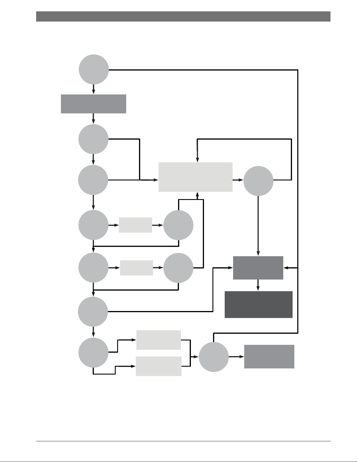
UPM Sequence of Operation (SOO) Flow Chart
YES
YES
YES
YES
YES
YES
YES
YES
YES
YES
YES
NO
NO
NO
NO
NO
NO
NO
NO
NO
NO
NO
Y1=1
V
>
18VAC
HPC = 1
LPC = 1
FRZ
>
TEMP
LIM
CON
>
0
INITIAL
POWER UP
T
>
ASC OR
RS SEC
TIME
>
30
SEC
TIME
>
120
SEC
COUNT = 2
Start Timer
Start Timer
CC Output = On
CC Output = Off
Blink Code On Status LED
Report Alarm Fault
Hard Lockout
ALR Output = On/Pulse
Blink Code On Status LED
Soft Lockout
Record Alarm
Start Counter (If Applicable)
Start
Anti Short Cycle
Start
Random Start Up
Lockout Can Be Set To
4 Via Dip Switch
Power/Switchs/Sensor
Status Check
LEGEND:
HPC - HIGH PRESSURE CUTOUT
LPC - LOW PRESSURE CUTOUT
FRZ - FREEZE PROTECTION CONDITION
CON - CONDENSATE OVERFLOW CONDITION
CC - COMPRESSOR COIL
ASC - ANTI SHORT CYCLE
RS - RANDDOM START
Sequence of Operation | 17LM Series Heat Pump
Figure # 14
8 733 905 315 (2013/9)Revised 09-13
18 | Application Considerations LM Series Heat Pump
APPLICATION CONSIDERATIONS
Cooling Tower/Boiler Systems
The cooling tower and boiler water loop
temperature is usually maintained between 50° F
to 100 ° F to assure adequate cooling and heating
performance.
In the cooling mode, heat is rejected from the unit
into the water loop. A cooling tower provides
evaporative cooling to the loop water thus
maintaining a constant supply temperature to the
unit. When utilizing open cooling towers, chemical
water treatment is mandatory to ensure the water
is free from corrosive elements. A secondary heat
exchanger (plate frame) between the unit and the
open cooling tower may also be used.
It is imperative that all air be eliminated from the
closed loop side of the heat exchanger to insure
against fouling. In the heating mode, heat is
absorbed from the water loop. A boiler can be
utilized to maintain the loop at the desired
temperature.
Water piping exposed to extreme low
ambient temperatures is subject to
freezing.
No unit should be connected to the supply or
return piping until the water system has been
completely cleaned and flushed to remove any dirt,
piping chips or other foreign material. Supply and
return hoses should be connected together during
this process to ensure the entire system is
properly flushed.
After the cleaning and flushing has taken place the
unit may be connected to the water loop and
should have all valves wide open. (Figure #15)
Consult the specification sheets for piping
sizes. Teflon tape sealer should be used
when connecting to the unit to insure
against leaks and possible heat exchanger
fouling.
Do not overtighten the connections. Flexible hoses
should be used between the unit and the rigid
system to avoid possible vibration. Ball valves
should be installed in the supply and return lines
for unit isolation and unit water flow balancing.
Pressure/temperature ports are recommended in
both supply and return lines for system flow
balancing. Water flow can be accurately set by
measuring the water-to-refrigerant heat
exchangers water side pressure drop.
.
See specification sheets for water flow vs.
pressure drop information.
LM Series Heat Pump8 733 905 315 (2013/9) Subject to change without prior notice
 Loading...