


KTS 530

Bosch Diagnostics|1 6 8 9 9 7 9 9 8 7 2 0 0 6 -0 9 -2 9
14 | KTS 530 / KTS 540 / KTS 570 | Contents
1. O p er a tor instr u c tions 15
1.1 Im p o r ta n t n o te s 15
1.2 S a fe ty in s t r u c tio n s 1
5
1.3 E le c tro m a g n e tic c o m p a tib ility ( E M C ) 15
1.4 D is p o s a l 1
5
1.5 B lu e to o th lim it a tio n s 15
1.6 Im p o r ta n t in fo r m a tio n re g a rd in g B lu e to o th 15
2. D esc r ip tion of u nit 1
6
2.1 A p p lic a tio n 1
6
2.2 R e q u ire m e n ts 16
2.2.1 H a rd w a re 16
2.2.2 O p e ra tin g s y s t e m 1
6
2.2.3 S o ftw a re 16
2.3 D e liv e r y s p e c ifi c a tio n 1
7
2.4 S p e c ia l a c c e s s o r ie s 17
2.5 S y s te m te s te r 1
7
2.5.1 D ia g n o s is te rm in a ls / M e a s u re m e n t
te r m in a ls 17
2.5.2 T e rm in a l s t r ip 1
7
2.5.3 F u n c tio n s o f L E D s A a n d B 18
2.5.4 A d a p te r in s e r t ( IB O X 01) 1
8
2.6 B lu e to o th 18
2.6.1 B lu e to o th U S B a d a p te r 1
8
2.6.2 In fo rm a tio n re g a r d in g B lu e to o th s y m b o ls 18
2.7 O p e ra tio n 19
2.7.1 C o n n e c tio n d ia g r a m 1
9
2.7.2 N o t e s c o n c e r n in g c o n t r o lle r d ia g n o s is 19
2.7.3
N o te s c o n c e rn in g th e m u lt im e te r
a n d o s c illo s c o p e 20
2.7.4 F irm w a re u p d a te 2
0
2.8 N o te s c o n c e rn in g fa u lts 20
2.8.1 D ia g n o s is h a rd w a re h a s n o t b e e n fo u n d . 20
2.8.2 N o c o m m u n ic a tio n w ith th e c o n tr o l u n it 2
0
2.8.3 In itia liz in g B lu e to o th d r iv e rs 21
3. Initia l sta rt-u p 22
3.1 A s s e m b ly m o u n t 22
3.2 E S I[ tro n ic ] s o ft w a re in s ta lla tio n 2
2
3.3 C o n n e c tio n 22
3.4 C o n fi g u ra tio n ( D D C ) 2
2
4. M a intena nc e 2
3
4.1 C le a n in g 2
3
4.2 M a in te n a n c e 23
4.3 S p a re a n d w e a r in g p a rts 2
3
5. Tec h nic a l d a ta 23
5.1 G e n e r a l d a ta 2
3
5.2 In te r fa c e p r o to c o ls 23
5.3 P o w e r p a c k 2
3
5.4 M u ltim e te r s p e c ifi c a tio n s 23
5.4.1 D C m e a s u r e m e n t ( C H 1 a n d C H 2) 2
3
5.4.2 A C a n d e ffe c tiv e v a lu e m e a s u re m e n t
( C H 1 a n d C H 2)
* ) 24
5.4.3 R e s is ta n c e m e a s u r e m e n t ( C H 1) 24
5.4.4 C u r re n t m e a s u re m e n t ( C H 1 a n d C H 2) 24
5.4.5 C o n tin u ity te s te r ( C H 1) 2
4
5.4.6 D io d e m e a s u re m e n t ( C H 1) 24
5.5 O s c illo s c o p e s p e c ifi c a tio n s 2
4
5.6 B lu e to o th C la s s 1 24
en
Contents
http://www.obd2be.com/
Bosch Diagnostics |1 689 979 987 2006-09-29
Operator instructions | KTS 530 / KTS 540 / KTS 570 | 15
1.5 B luetooth lim itations
There are limitations in the following countries
(e. g. Bluetooth modules may only be used in enclosed
rooms) when operating Bluetooth Class 1 modules:
Egypt, France, J ordan, Pakistan, Peru, Saudi-Arabia,
Sri Lanka, Thailand and Turkey.
In the following countries, no Bluetooth modules
are to be used (Status: March 2006):
Algeria, Ethiopia, Bolivia, Burma, Georgia, Guatemala,
Cambodia, Q atar, North K orea, Senegal, South Africa,
Syria, United Arab Emirates, W est Sahara.
1. O p er a tor instr u c tions
1.1 Im portant notes
Important notes on the agreement pertaining to copyright, liability and warranty, about the user group and
obligation on the part of the contractor, are available in
the separate instructions entitled "Important notes and
safety instructions" on Bosch test equipment. These are
to be read thoroughly before using, connecting and operating the product and they must be observed.
1.2 Safety instructions
All safety instructions are available in the separate instructions "Important notes and safety instructions" on
Bosch test equipment. These are to be read thoroughly
before using, connecting and operating the product and
they must be observed.
1.3 E lectrom ag netic com patib ility ( E MC)
This product is a Class A product in accordance with
EN 55 022.
This product can cause radio interference in the
home; in this case the operator may be asked to
implement appropriate measures.
1.4 Disposal
This product is sub ject to E uropean g uidelines 2002/9 6/E G ( W E E E ) .
O ld e le ctrical and e le ctr onic d e v ice s, inclu d ing
cab le s and acce ssorie s or b atte rie s m u st b e
d isp ose d of se p ar ate to hou se hold w aste .
Please use the return and collection systems in place for disposal in your area.
Damage to the environment and hazards to
personal health are prevented by properly
disposing of old equipment.
0
1.6 Im portant info rm ation reg arding
B luetooth
Bluetooth is a wireless connection in the unlicensed
2.4 Ghz-ISM-Band (ISM: Industrial, Scientific, Medical).
This frequency range is not subject to any governmental
laws and may be used in most countries without a license
(Ex ceptions are found in chap. 1.5). This results in many
applications and devices transmitting on this frequency
band however. This can cause frequency interference
between these devices.
Depending on the environmental conditions, disturbance
can occur in the Bluetooth connection, e. g. in W LAN
connections (W LAN: W ireless Local Area Network),
wireless telephones, radio-controlled thermometers,
radio-controlled garage door openers, radio-controlled
light switches or radio-controlled alarm systems.
Bluetooth can lead to interference in the bandwidth
of the W LAN-network. The antennas of Bluetooth and
W LAN devices should be positioned at least 30 centi
meters apart. Bluetooth-USB adapters and W LAN must
not be placed in adjacent USB sockets in the PC/Lap
top. A USB ex tension cable (special accessories) should
be used to ensure that the Bluetooth-USB adapter is
separate from the W LAN stick.
Generally, people who wear a pacemaker or other
essential electronic device should ex ercise ex treme
caution when using wireless technology, as it may
impair the function of their particular device.
Note the following to ensure that your connectivity is as
good as possible:
The Bluetooth wireless signal always looks for the
shortest path. Set up a PC/Laptop with Bluetooth
USB adapter so that there are as few obstacles,
such as e. g. steel doors and concrete walls, that
could disturbed the radio signal to and from the
K TS 540 or K TS 570 as possible.
If the PCis in a Bosch trolley (e. g. FSA 740, BEA 850),
the Bluetooth USB adapter should be positioned
outside of the trolley using a USBex tension cable.
Use USB ex tension cable (special accessory)
1 684 465 564 (1 m) or 1 684 465 565 (3 m).
If there are problems with the Bluetooth connection,
you can activate the USB connection and use it instead of the Bluetooth connection.
0
0
R
R
R
en
http://www.obd2be.com/
Bosch Diagnostics|1 689 979 987 2006-09-29
16 | KTS 530 / KTS 540 / KTS 570 | Description of unit
2. D escription of unit
2.1 A pplication
KTS 530, KTS 540 and KTS 570 (hereinafter referred to as
KTS modules) are modules for controller diagnosis. The
functionality differences are shown in the following table:
F unction KTS 530 KTS 540 KTS 570
Controller diagnosis
X X X
1 channel multimeter X X
X
2 channel multimeter
– – X
2 channel oscilloscope
– –
X
2 channel diagnosis oscilloscope
– –
X
Bluetooth wireless connection
– X X
USB connection X X X
KTS modules can perform the following functions with
ESI[tronic]:
C ontroller diagnosis, with e.g.
Read error memory
Display actual values
Initiate actuators
Use of other controller-specific functions
M ultimeter measurements for
V oltage measurement
Resistance measurement
Current measurement (only with special
accessory current measuring clips or shunt)
2 channel oscilloscope for determining
measurement values (K T S 5 70 only ) .
2 channel diagnosis oscilloscope for testing the
controller diagnosis interface (K T S 5 70 only ).
R
I
I
I
I
R
I
I
I
R
R
2.2 R eq uirements
2.2.1 H ardw are
PC/Laptop with at least one free USBinterface.
KTS modules can be used with the following Bosch
products:
Emissions System Analysis
(*)
FSA 740
BEA 810, BEA 840, BEA 850
(*)
(*)
D e p e n d in g o n th e so ftw a re v e rs io n .
2.2.2 Operating system
Operating system U SB Bluetooth
WIN XP
X X
2.2.3 Softw are
Operation of the KTS modules requires the installation
and enabling of software ESI[tronic]-DV D 2006/1 and
ESI[tronic]-CD 2006/3 U (blue U ) on the PC/Laptop.
Extra costs apply in this case.
R
R
R
en
http://www.obd2be.com/
Bosch Diagnostics |1 689 979 987 2006-09-29
Description of unit | KTS 530 / KTS 540 / KTS 570 | 17
2.3 Deliv ery specification
Description Order N umber
System tester KTS 530
(*)
System tester KTS 540
(*)
System tester KTS 570
(*)
1 687 022 437
1 687 022 436
1 687 022 994
Bluetooth USB adapter (KTS 540/KTS 570) 1 687 023 382
OBD diagnosis cable 3 m (KTS 530) 1 684 465 557
OBD diagnosis cable 1.5 m (KTS 540/KTS 570)
1 684 465 555
UNI connection cable 4 core 1 684 463 539
USB connection cable 3 m 1 684 465 562
Power pack
Power supply cable
1 687 022 889
1 684 461 106
Measuring cable blue (KTS 530/KTS 540) 1 684 430 066
Measuring cable yellow (KTS 530/KTS 540) 1 684 430 067
Measuring cable red/black (KTS 570) 1 684 463 214
Measuring cable blue/yellow (KTS 570) 1 684 463 550
Test tip red (1x, with KTS 570 2x) 1 684 485 035
Ground cable black 1 684 430 068
Terminal clip, black 1 684 480 022
Case 1 685 438 145
Mount
with sheet-metal screw (2x)
and fillister head screw (3x)
1 681 398 030
2 910 611 406
2 910 641 118
DVD1 ESI[tronic] 2006/1
Diagnosis and technology
DVD2 ESI[tronic] 2006/3 U
1 987 729 601
1 987 729 041
Important information and safety instructions 1 689 979 922
Product description
(KTS 530/KTS 540/KTS 570)
1 689 979 987
(*)
depending on order
2.4 Special accessories
Information on special accessories, such as e.g.
vehicle-specific connecting cables, additional measuring
cables and connecting cables can be obtained from your
Bosch representative.
2.5 System tester
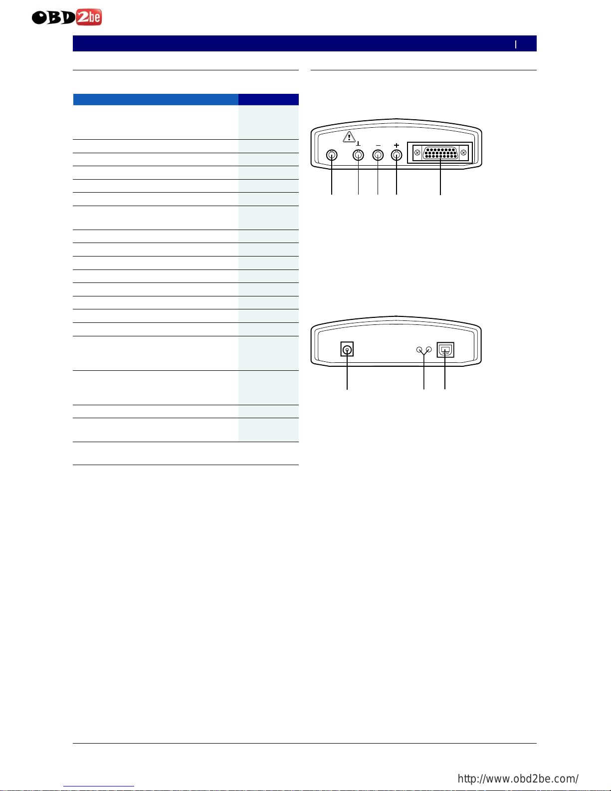
2.5.1 Diagnosis terminals/Measurement terminals
CH2
CH1
D IA G
m a x . 6 0 V
459802/12 Ko
1 2
3
4
5
F ig. 1: Diagnosis terminals/Measurement terminals
1 M easu ring inpu t C H 2 (only for K T S 57 0 )
2 G N D soc k et
3 M easu ring inpu t C H 1(– )
4 M easu ring inpu t C H 1(+ )
5 C onnec tion O B D diagnosis c ab le (DIA G )
2.5.2 Terminal strip
15V DC
U S B
459802/11 Ko
1 2 3
A
B
F ig. 2: Terminal strip
1 P ower su pply c onnec tion
2 L E D A and L E D B (see c hap. 2.5.3)
3 U S B c onnec tion
en
http://www.obd2be.com/
 Loading...