

Bosch IUI-MAP0001 User Manual
MAP Control Center
IUI-MAP0001
en User Guide


MAP Control Center Table of Contents | en 3
Bosch Security Systems, Inc. User guide F.01U.168.328 | 03 | 2011.05
Table of Contents
1System Overview 5
1.1 Certifications 5
1.2 MAP Control Center Description 5
1.2.1 LCD Screen 5
1.2.2 MAP Control Center LEDs 5
1.3 Control Center Maintenance 5
1.4 Idle Screen 6
1.5 Logging In 7
1.6 Screen Elements 8
2Operation 10
2.1 Alarm Tasks 10
2.1.1 Silence Alarms 10
2.1.2 Clear Alarms 10
2.1.3 View Event Memory 10
2.1.4 Clearing An Anti-masking Message 11
2.2 Searching and Sorting/Filtering 11
2.2.1 Search 12
2.2.2 Sort/Filter 12
2.3 Arm - Using the Control Center 13
2.3.1 Arm All Areas 14
2.3.2 Arm Selected Areas 14
2.3.3 Arm Control Panel (Local) Area 15
2.4 Disarm – Using the Control Center 15
2.4.1 Disarm All Areas 16
2.4.2 Disarm Selected Areas 16
2.4.3 Disarm Control Panel Area 17
2.5 Users 17
2.5.1 Add User 18
2.5.2 Delete User 26
2.5.3 Edit User 27
2.5.4 Change Passcode 29
2.6 Schedules 29
2.7 Status 31
2.7.1 View Area Status 32
2.7.2 View Device Status 34
2.7.3 Bypass/Unbypass Device 37
2.7.4 Unbypass All Devices 38
2.8 Service 39
2.8.1 Event History 40
2.8.2 View Version Information 43
2.8.3 Enable/Disable Device 44
2.8.4 Set Time and Date 45
2.8.5 Walk Test 46
2.8.6 Motion Detector Test 50
2.8.7 Bell and Indicator Test 51
2.8.8 Change/View Output State 52

4 en | Table of Contents MAP Control Center
F.01U.168.328 | 03 | 2011.05 User guide Bosch Security Systems, Inc.
2.8.9 Manufacturer Authorization 53
2.8.10 Adjust Volume/Brightness 53
2.8.11 Chime Mode On/Off 54
2.9 Internal Program 54
2.10 Event Memory 55
2.10.1 View Event Memory 56
2.10.2 Clear Event Memory 56
2.10.3 View Alarm Counter 56
2.10.4 Silence 57
2.11 RPS 57

MAP Control Center System Overview | en 5
Bosch Security Systems, Inc. User guide F.01U.168.328 | 03 | 2011.05
1 System Overview
1.1 Certifications
The control center is designed to comply with the following certifications and standards:
1.2 MAP Control Center Description
The MAP control center is an input device for the Modular Alarm Platform 5000 system. Each
control center has a vibrant-color 14 cm (5.7 in.) LCD screen. The durable touch screen
provides access to the various system functions through an interface with intuitive buttons.
Users touch the images directly on the screen to arm, disarm, or select other menu options.
Based on the user’s preference, text is shown in German, English, French, or Dutch.
1.2.1 LCD Screen
To operate the MAP control center, apply moderate pressure to the keys and buttons shown
on the screen. To avoid damage to the touch-sensitive foil do not use sharp objects.
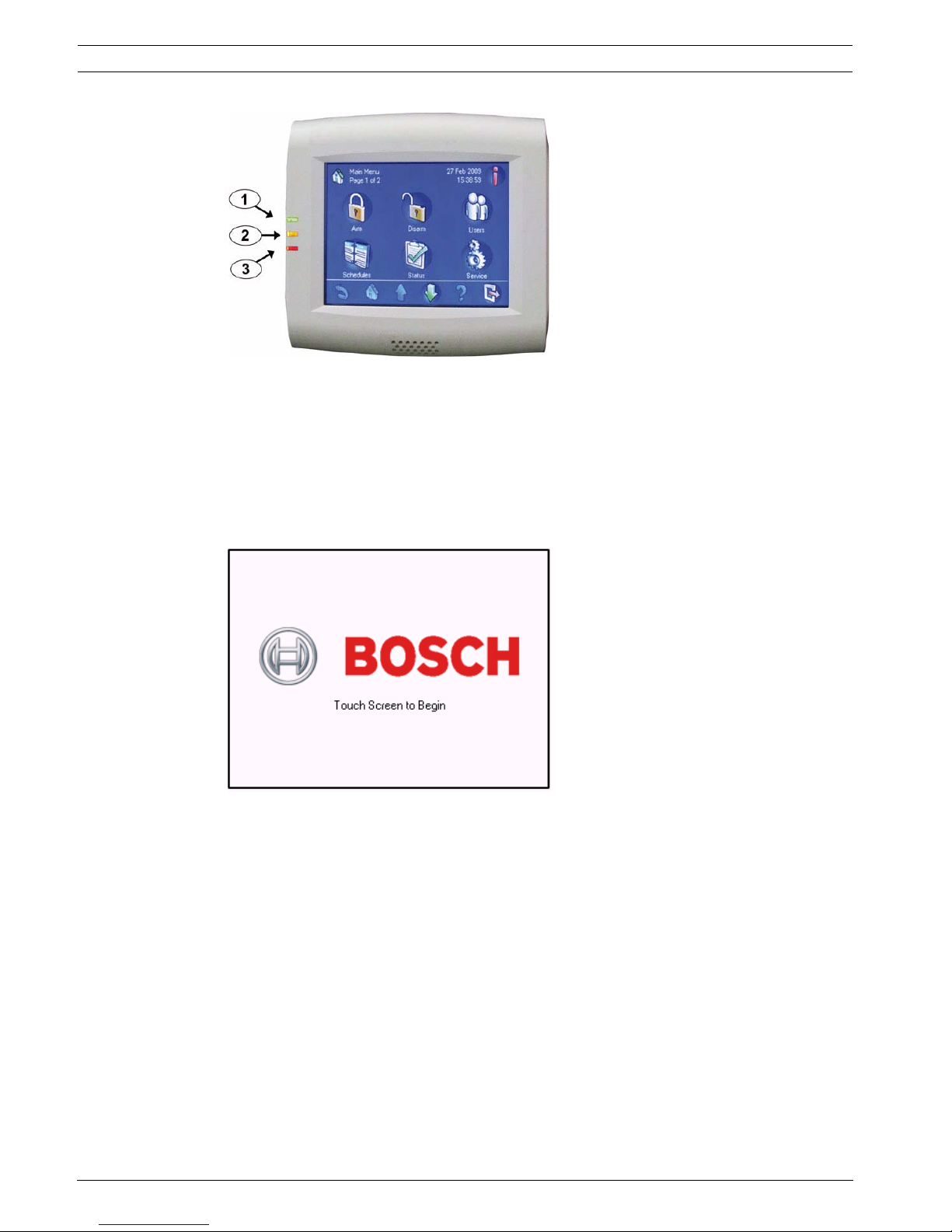
1.2.2 MAP Control Center LEDs
Three light-emitting diodes (LEDs) are located on the left edge of the MAP control center
(Figure 1.1, Page 6):
– Green LED: Indicates that the control center is communicating with the control panel.
– Yellow LED: The default behavior indicates if there is a trouble condition or any
component is blocked or bypassed in the security system
– Red LED: The default behavior indicates that an alarm condition exists in the security
system
1.3 Control Center Maintenance
If the control center housing is dirty, clean it with a soft dampened cloth. Do not use corrosive
or abrasive cleaners. Make sure that no fluid gets inside of the housing. To remove
fingerprints or dust from the LCD screen, use a soft cloth that you have dampened slightly
with water.
Region Certification
GERMANY VdS Class C, VdS G 111040
Europe CE Conformité Européene
EN50131-1/3 grade 3 Alarm Systems – Intrusion
Systems
6 en | System Overview MAP Control Center
F.01U.168.328 | 03 | 2011.05 User guide Bosch Security Systems, Inc.
Figure 1.1 Control Center LEDs
1.4 Idle Screen
The control center shows the Idle screen (Figure 1.2, Page 6) when it is not in use. To use the
system, touch the control center display.
Figure 1.2 Idle screen
1 – Green LED
2 – Yellow LED
3 – Red LED
MAP Control Center System Overview | en 7
Bosch Security Systems, Inc. User guide F.01U.168.328 | 03 | 2011.05
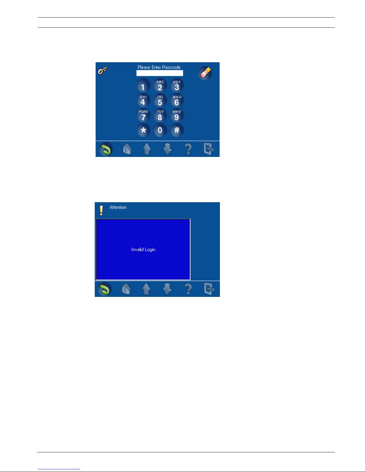
1.5 Logging In
Use the Login screen (Figure 1.3, Page 7) to enter your passcode.
Figure 1.3 Login screen
If the system does not recognize the passcode, the control center shows the Invalid Login
screen (Figure 1.4, Page 7). To empty the passcode field, press Clear (the pencil eraser
button). After the user enters a valid passcode, the touch screen shows the Main Menu
(Figure 1.5, Page 8).
Figure 1.4 Invalid Login screen
8 en | System Overview MAP Control Center
F.01U.168.328 | 03 | 2011.05 User guide Bosch Security Systems, Inc.
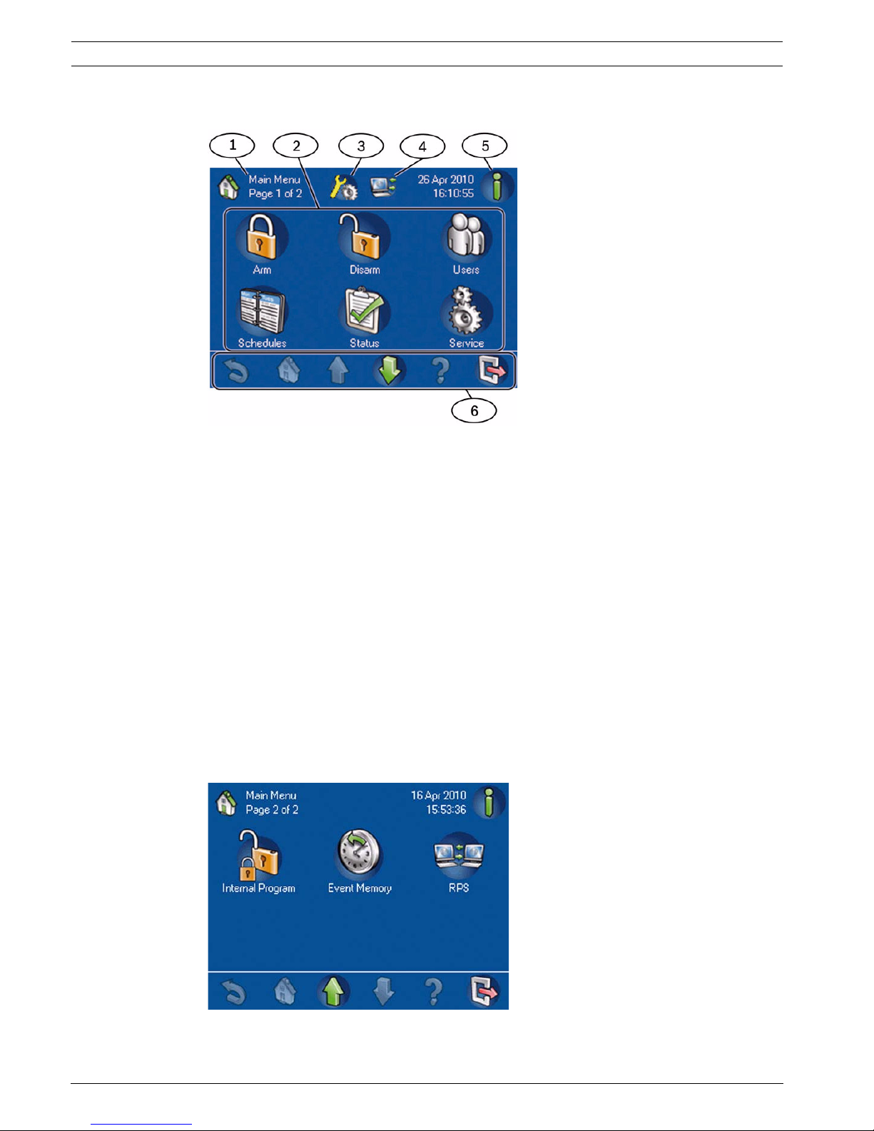
1.6 Screen Elements
Figure 1.5 Main Menu – page 1
Figure 1.6 Main Menu – page 2
1 – Screen name: identifies the active screen.
2 – Menu buttons: Press a menu button to perform a task.
3 – Installer Mode Icon: Indicates that the control panel is in installer mode.
4 – RPS Connected Icon: Indicates that RPS is connected to the control panel.
5 – Information button: If it is flashing, press this button to view additional system information and to
clear the events, alarms or troubles. For more Event Memory information, refer to Section 2.1.3 View
Event Memory, page 10.
– If the Information button is flashing red, there are system events and alarms that the user has
not cleared.
– If the Information button is flashing yellow, there are system troubles which the user has not
cleared.
– If the Information button is green, no additional system information is available.
6 – Navigation bar: Press the buttons in the navigation bar to find tasks or to view system information.
Refer to Table 1.1, Page 9. Buttons in the navigation bar that appear without their normal colors are
not activated.
MAP Control Center System Overview | en 9
Bosch Security Systems, Inc. User guide F.01U.168.328 | 03 | 2011.05
After the user presses a button, the touch screen shows the task buttons contained within
that folder. For example, Figure 2.45 on Page 32 shows the Status tasks.
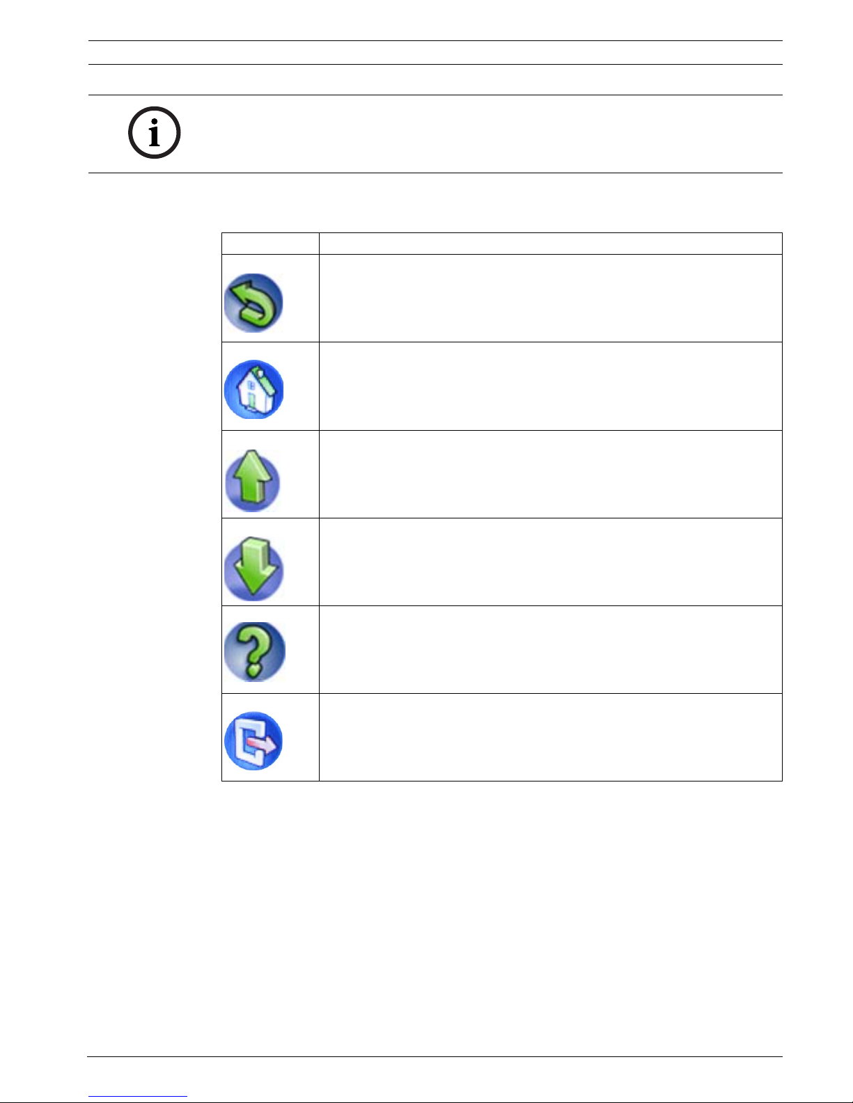
Table 1.1 Navigation Bar description
NOTICE!
The buttons on your touch screen might be different from the buttons shown in Figure 1.5 on
Page 8 and Figure 1.6 on Page 8. The buttons on your touch screen are determined by your
user authority level.
Button Description
Back: Shows the previous screen.
Home: Shows the Main Menu.
Page up: Shows the previous page on screens with more than one page.
Page down: Shows the next page on screens with more than one page.
Help: Shows helpful information about the active screen.
Exit: Shows the Idle screen (Figure 1.2, Page 6).
10 en | Operation MAP Control Center
F.01U.168.328 | 03 | 2011.05 User guide Bosch Security Systems, Inc.
2 Operation
2.1 Alarm Tasks
2.1.1 Silence Alarms
If the system generates an alarm, press the touch screen and enter your passcode (Figure 1.3,
Page 7). If the system accepts your passcode, the touch screen shows the External Intrusion
Alarm screen (Figure 2.1, Page 10).
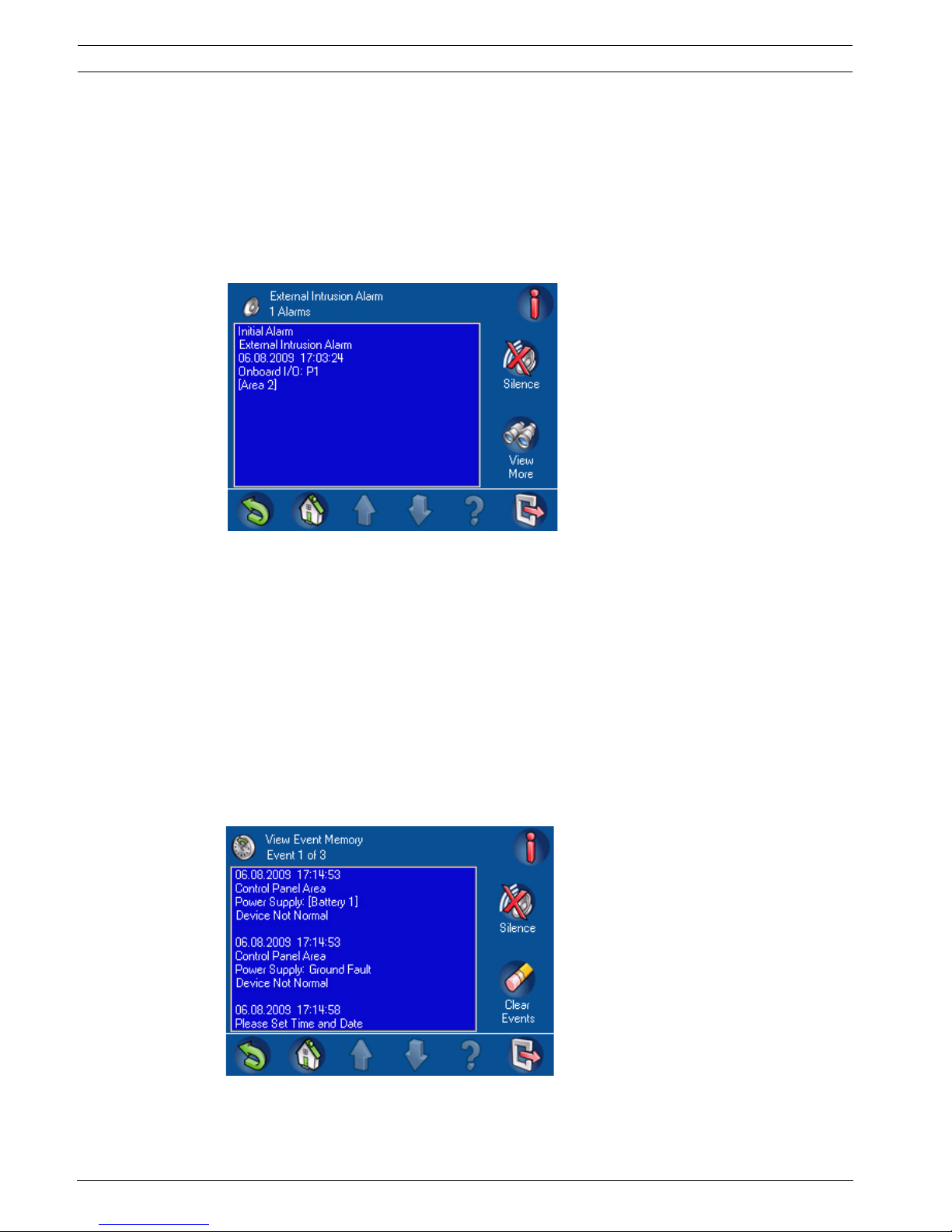
Figure 2.1 External Intrusion Alarm screen
To silence the alarm, press Silence. If the system recorded more than one alarm, the screen
shows the first and last alarms. Press View More to see events in the event memory. For more
information about event memory, refer to Section 2.1.3 View Event Memory, page 10.
2.1.2 Clear Alarms
After silencing an alarm, the user must clear the alarm. From the alarm screen (Figure 2.1,
Page 10), press View More to open the View Event Memory screen (Figure 2.2, Page 10). To
clear the alarm, press Clear Events.
2.1.3 View Event Memory
If the Information button on the Main Menu (Figure 1.5, Page 8) flashes red or yellow, press
the Information button to view the View Event Memory screen (Figure 2.2, Page 10). For
additional event memory options, refer to Section 2.10 Event Memory, page 55.
Figure 2.2 View Event Memory screen

MAP Control Center Operation | en 11
Bosch Security Systems, Inc. User guide F.01U.168.328 | 03 | 2011.05
If your passcode authorizes the clearing of alarms and other events, press Clear Events. If you
cannot clear certain events because you do not have the necessary access rights, then the Not
Authorized screen appears on the control center. In this case, please notify your installer or
maintenance engineer. For more information about viewing event memory, refer to
Section 2.1.3 View Event Memory, page 10.
2.1.4 Clearing an Anti-masking Message
1. Turn on the Motion Detector Test for the area in which the point is located (refer to
Section 2.8.6 Motion Detector Test, page 50 )
2. Remove the object masking the point and then trigger the point using motion.
3. Turn off the Motion Detector Test again. The anti-masking message is now cleared.
2.2 Searching and Sorting/Filtering
Some functions in the MAP system user interface call for or require searching, sorting, or
filtering. Where these functions are possible, the Search and Sort/Filter (Table 2.1, Page 11)
buttons appear on the screen.
Table 2.1 Search and Sort/Filter button descriptions
NOTICE!
The system displays events with the newest event being displayed first.
Button Description
Search: Shows the Alphanumeric Keypad screen (Figure 2.3, Page 12).
Sort/Filter: Shows a list of sort categories appropriate to the function, and
the A-Z and Z-A buttons.
A-Z: Sorts in alphabetical order.
Z-A: Sorts in reverse alphabetical order.
12 en | Operation MAP Control Center
F.01U.168.328 | 03 | 2011.05 User guide Bosch Security Systems, Inc.
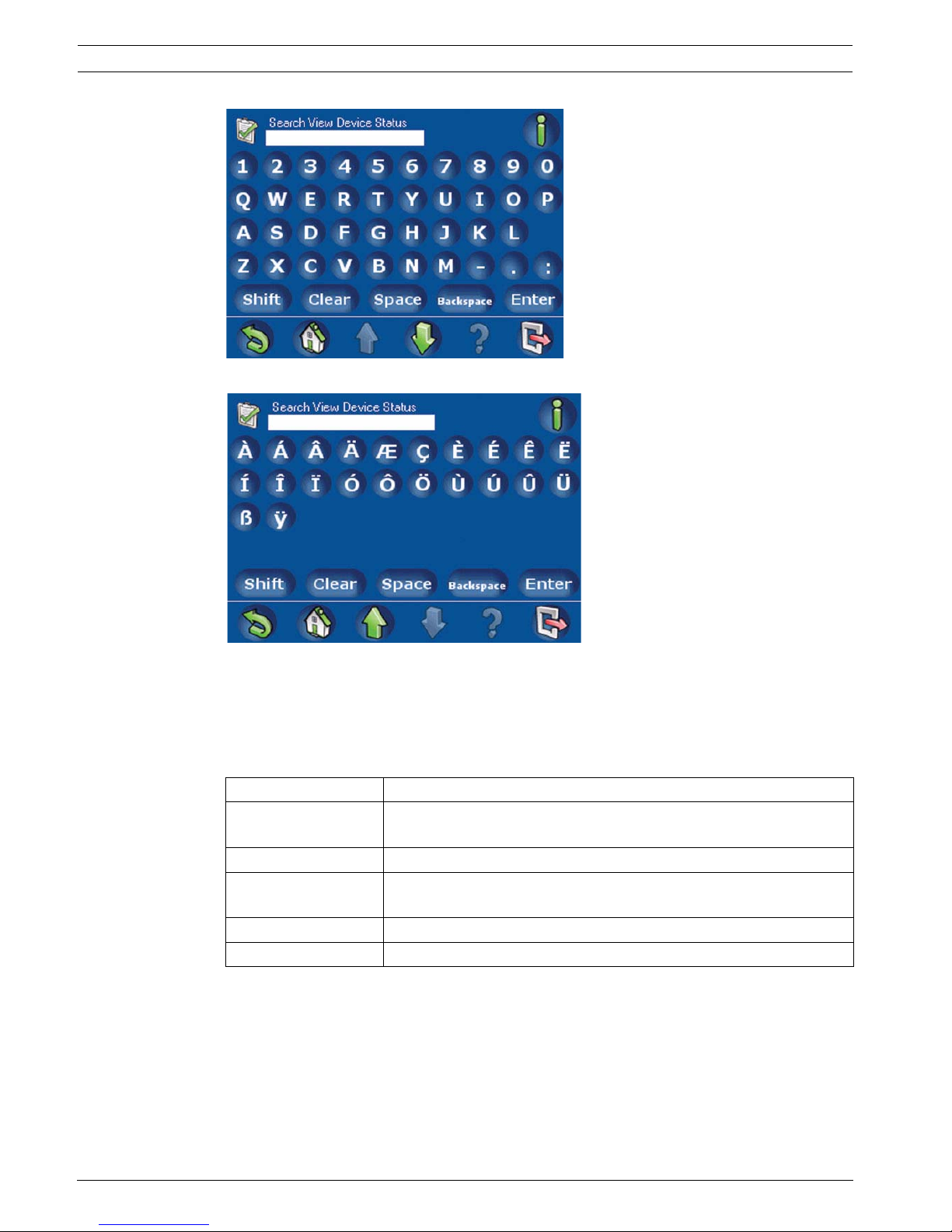
Figure 2.3 1. Alphanumeric Keypad screen 1
Figure 2.4 2. Alphanumeric Keypad screen 2
2.2.1 Search
Search uses an alphanumeric keypad display for input. The alphanumeric keypad display has
the numerals 0 - 9, a QWERTY arrangement of letters with additional special characters, and
five commands (refer to Table 2.2, Page 12).
Table 2.2 Alphanumeric Keypad Command descriptions
2.2.2 Sort/Filter
When you use the Sort/Filter function, the sorting can be alphabetical (from A - Z or from Z to
A) for all devices or all areas, for example, or the function can be narrowed by selecting
faulted, bypassed, unbypassed, enabled, or disabled devices.
All areas can be sorted, or the sorting function can be narrowed by selecting armed,
disarmed, ready to arm, not ready to arm, ready to disarm, or not ready to disarm areas. More
Command Description
Shift Creates capital letters. Press once. The next letter pressed is
capitalized.
Clear Clears all input in the Search field.
Space Inserts a space (same function as the spacebar on a manual
keyboard).
Backspace Clears the previous character.
Enter Starts the search process.
MAP Control Center Operation | en 13
Bosch Security Systems, Inc. User guide F.01U.168.328 | 03 | 2011.05
information is provided in the sections that cover the commands that allow sorting and
filtering.
2.3 Arm - Using the Control Center
The Arm menu allows the user to arm all areas, arm selected areas, or arm the control panel
area.
On the Main Menu (Figure 1.5, Page 8), press Arm, then select an arming option from the onscreen buttons (Arm All Areas, Arm Selected Areas, or Arm Control Panel Area) on the Arm
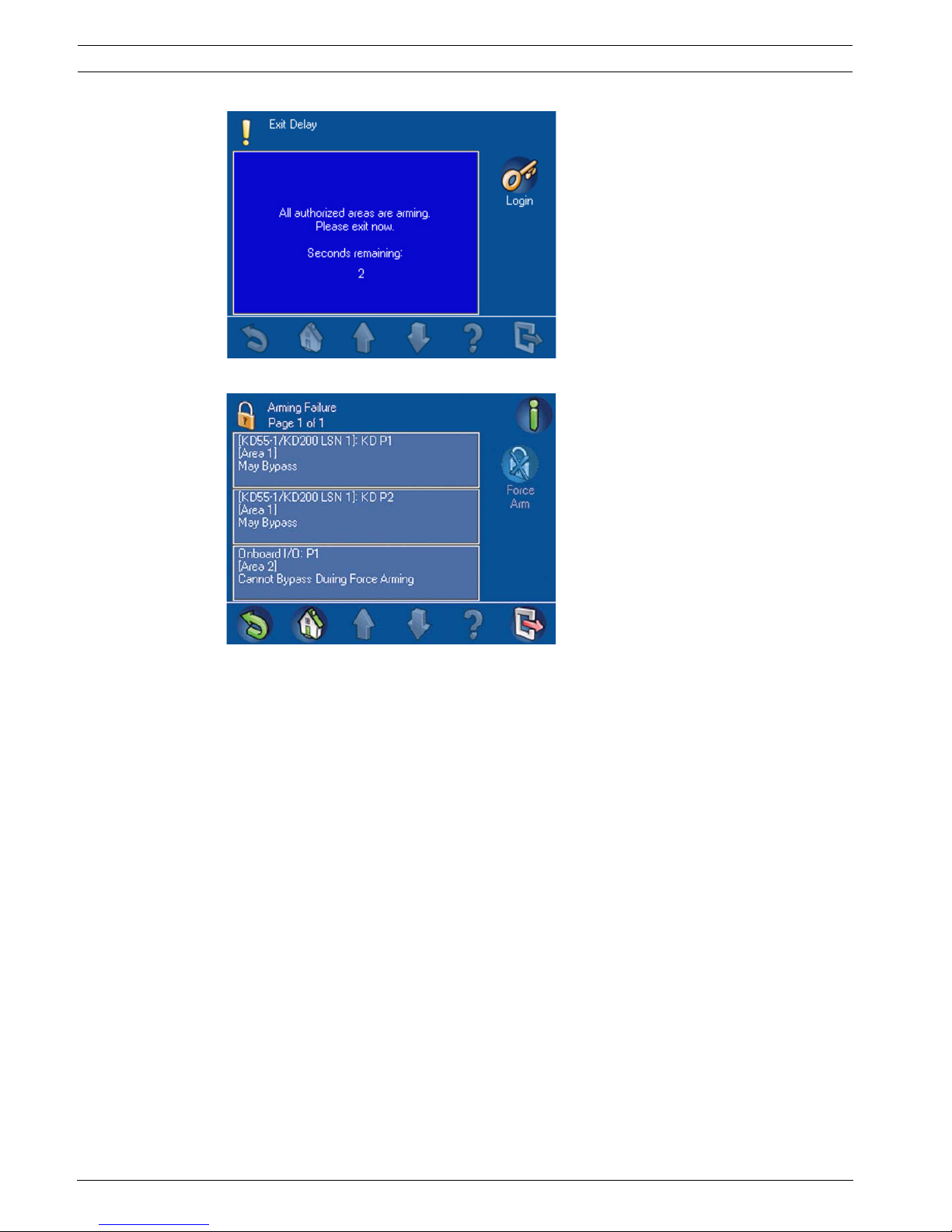
Menu (Figure 2.5, Page 13). Selecting an area that is Ready to Arm initiates the arming
sequence and displays the Exit Delay screen (Figure 2.6, Page 14) which indicates how much
time you have to evacuate the arming area(s) before your presence sets off an alarm.
Selecting an area that is Not Ready to Arm displays an Arming Failure screen (Figure 2.7,
Page 14) which indicates which area(s) can be force armed [armed by forcing bypass (refer to
Section 2.7.3 Bypass/Unbypass Device, page 37) of all points that are not ready to be armed]
and which areas cannot be force armed.
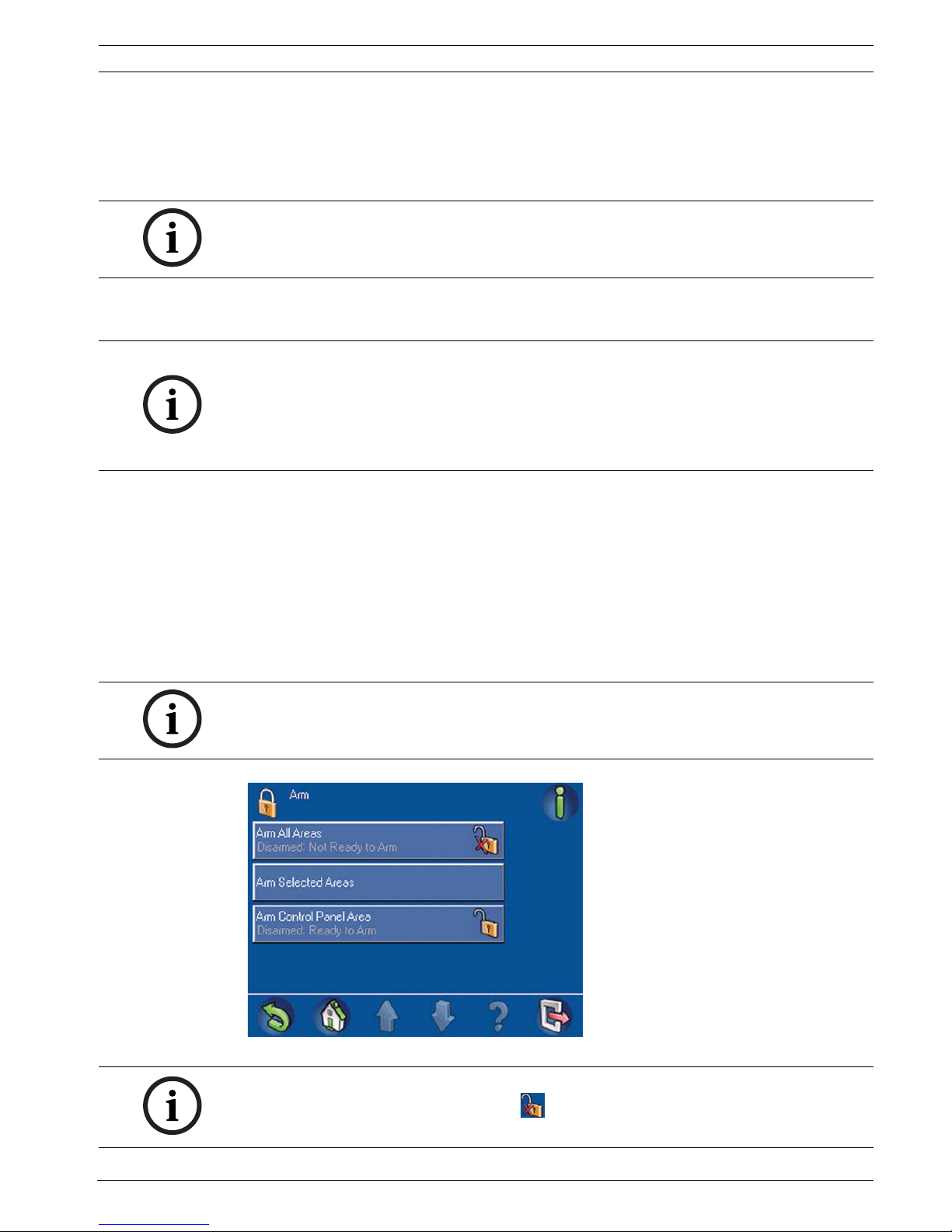
Figure 2.5 Arm menu
NOTICE!
A system installed with Smartkey or Blocklock controls can only be armed or disarmed by
those controls. It cannot be armed or disarmed using a control center.
NOTICE!
For the system default, the area containing the control center is the local area. During
installation, each control center can be assigned to a specific area making that area the local
area for that control center. Therefore, the displayed button name on each control center is
unique for each installation. Depending on how your system is configured, you might need to
arm the control panel area first.
NOTICE!
Force arming is not available when a related area must be armed first, when too many points
are already bypassed, or when an area contains specific unbypassable points.
NOTICE!
Clicking on the Not Ready to Arm icon ( ) provides information on why the area is not
ready to arm.
14 en | Operation MAP Control Center
F.01U.168.328 | 03 | 2011.05 User guide Bosch Security Systems, Inc.
Figure 2.6 Exit Delay screen
Figure 2.7 Arming Failure screen
2.3.1 Arm All Areas
From the Arm menu, press the Arm All Areas button. As above, if all areas are Ready to Arm,
the Exit Delay screen is displayed; if not, the Arming Failure screen opens with the lock button
in the locked position and the armed status showing on the Arm All Areas button.
2.3.2 Arm Selected Areas
From the Arm menu (Figure 2.5, Page 13), press the Arm All Areas button. The Arm Selected
Areas screen (Figure 2.8, Page 15) opens. The text and the lock button show status
information on the button for each area. To arm an area, press the button for an area that is
not already armed; then press the Arm button.

MAP Control Center Operation | en 15
Bosch Security Systems, Inc. User guide F.01U.168.328 | 03 | 2011.05
Figure 2.8 Arm Selected Areas screen
To sort the list of areas before selecting some to arm, press the Sort/Filter button. Refer to
Table 2.3, Page 15 for the possible arming indicators.
Table 2.3 Arming indicators
2.3.3 Arm Control Panel (Local) Area
From the Arm menu (Figure 2.5, Page 13), press the Arm Control Panel Area button.
The Arm menu opens with the lock button in the locked position and the area’s armed status
showing on the Arm Control Panel Area button.
2.4 Disarm – Using the Control Center
The Disarm menu allows the user to disarm all areas, disarm selected areas, or disarm the
entire control panel (or installation-specific local) area. On the Main Menu (Figure 1.5,
Page 8), press Disarm, then select a disarming option from the on-screen buttons on the
Disarm menu (Figure 2.9, Page 16).
Indicator Description
Disarmed Area currently disarmed
Ready to Arm All points in the area are ready
to arm
Not Ready to Arm Some points in the area are
faulted and not ready to arm; all
points must either be returned
to normal or bypassed.
Armed Area currently armed
NOTICE!
Depending on how your system is configured, the displayed button name on each control
center is unique for each installation.
16 en | Operation MAP Control Center
F.01U.168.328 | 03 | 2011.05 User guide Bosch Security Systems, Inc.
Figure 2.9 Disarm menu
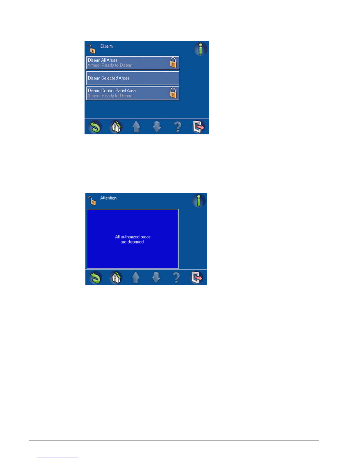
2.4.1 Disarm All Areas
From the Disarm menu (Figure 2.9, Page 16), press the Disarm All Areas button. The control
center display shows the message: Attention - All authorized areas are disarmed
(Figure 2.10, Page 16). Then the Disarm menu opens with the lock button in the unlocked
position and the disarmed status showing on the Disarm All Areas button.
Figure 2.10 Attention message: All authorized areas are disarmed
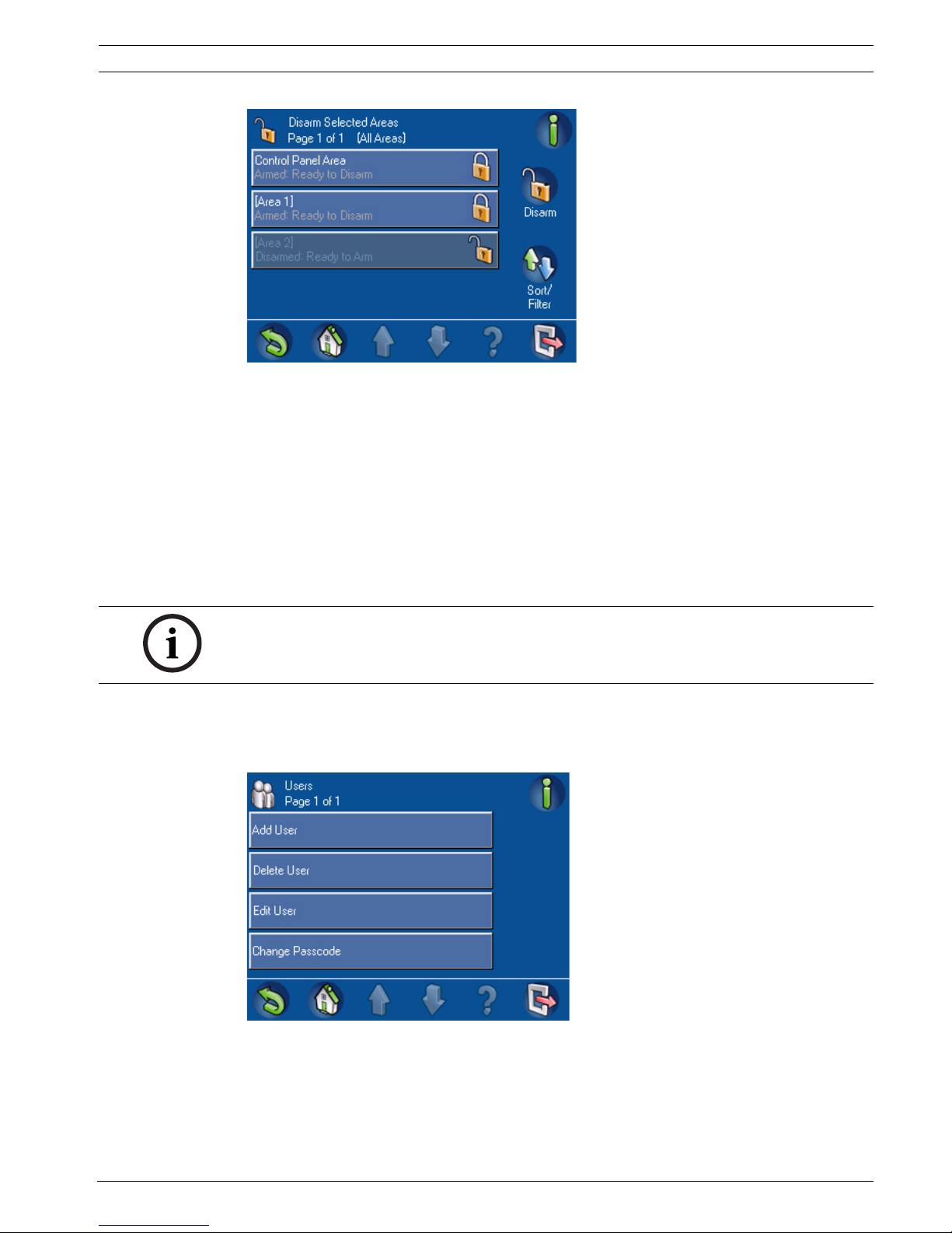
2.4.2 Disarm Selected Areas
From the Disarm menu, press the Disarm Selected Areas button. The Disarm Selected Areas
screen (Figure 2.11, Page 17) opens. The text and the lock button show status information on
the button for each area. To disarm an area, press the button for an area that is not already
disarmed; then press the Disarm button. To sort the list of areas before selecting some to
disarm, press the Sort/Filter button.
MAP Control Center Operation | en 17
Bosch Security Systems, Inc. User guide F.01U.168.328 | 03 | 2011.05
Figure 2.11 Disarm Selected Areas screen
2.4.3 Disarm Control Panel Area
From the Disarm menu (Figure 2.9, Page 16), press the Disarm Control Panel Area button.
Usually, this button is the area where the control center is located, but it could be any area
designated as the local area. The button name is unique at each installation.
To disarm the control panel area, press the Control Panel Area button then press the Disarm
button. The lock icon on the Control Panel Area button changes to the unlocked position and
the area's disarmed status shows on the button.
2.5 Users
The Users menu allows the user to add (up to the maximum number of users allowed), delete
or edit a user’s profile or to change a user’s passcode. On the Main Menu (Figure 1.5, Page 8)
press Users, then select the user category from the on-screen buttons (Figure 2.12, Page 17).
Figure 2.12 Users menu
NOTICE!
The options to perform user-related operations are restricted by permission set/access
profile.
18 en | Operation MAP Control Center
F.01U.168.328 | 03 | 2011.05 User guide Bosch Security Systems, Inc.
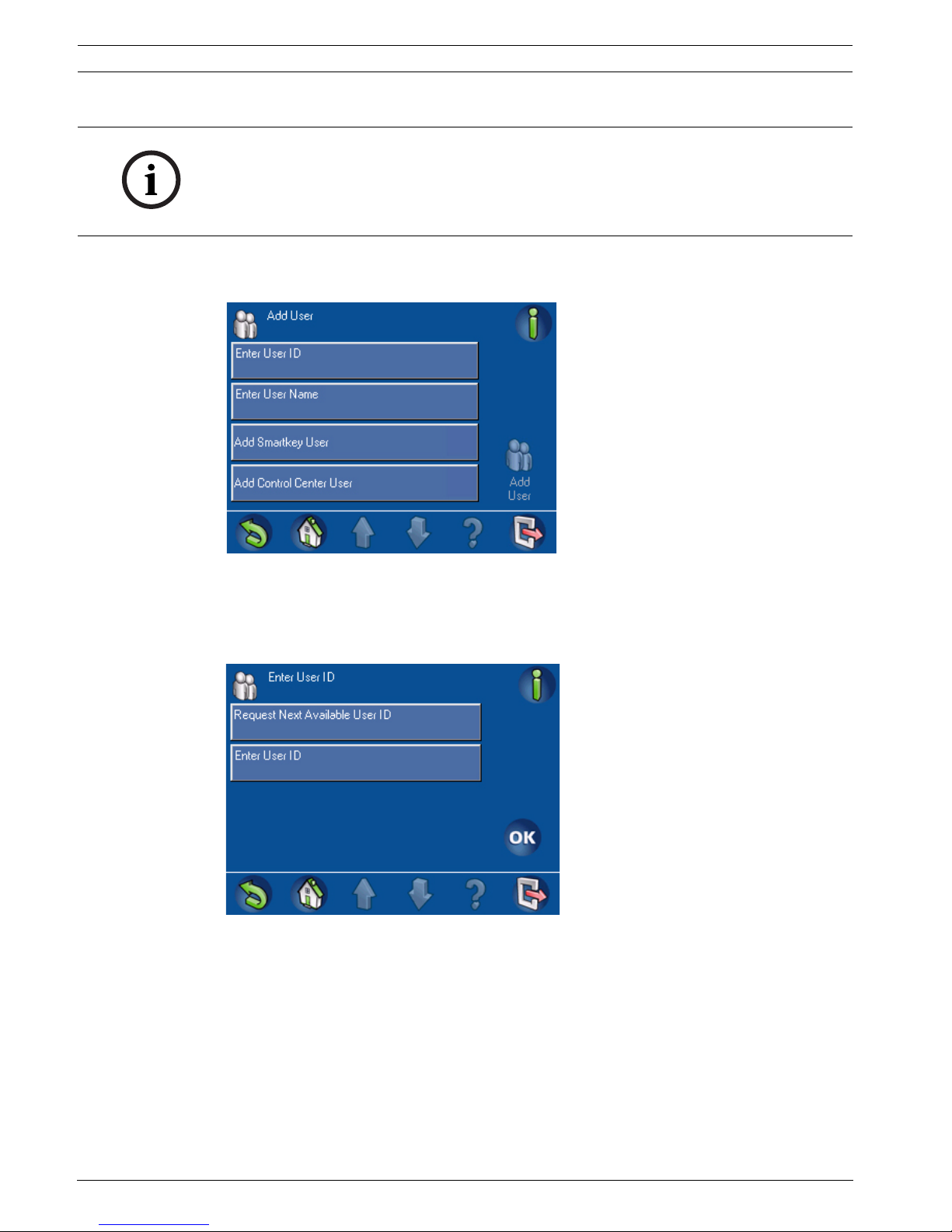
2.5.1 Add User
1. From the Users menu (Figure 2.12, Page 17), press Add User. The Add User screen
(Figure 2.13, Page 18) opens.
Figure 2.13 Add User screen
Enter User ID
2. From the Add User screen (Figure 2.13, Page 18), press Enter User ID.
The Enter User ID screen (Figure 2.14, Page 18) opens.
Figure 2.14 Enter User ID screen
3. Press Enter User ID to enter a specific three-digit user ID, or press Request Next
Available User ID to have the system assign a user ID. When you select Enter User ID,
the Enter User ID telephone keypad display screen (Figure 2.15, Page 19) opens.
a. Press the numbered buttons on the keypad screen. Each number appears in the
Enter new user ID field. Press Clear to make corrections.
b. Press OK to enter the specific user ID.
NOTICE!
A Smartkey user must also be entered as a control center user. Refer to Section Add Smartkey
User, page 20.
A control center user is not required to be a Smartkey user. Refer to Section Add Control
Center User, page 22.
 Loading...