

Bosch ITS-D6686-UL Installation Manual
Conettix ITS-D6686-UL
Installation Guide
Ethernet Network
EN
Adapter

Conettix ITS-D6686-UL | Installation Guide | Contents
Contents
1.0 Introduction ...................................................... 3
1.1 Network Interface ........................................... 3
1.2 Serial Interface ................................................ 3
1.3 LEDs ................................................................. 3
2.0 Installation ........................................................ 4
2.1 All Installations ................................................ 4
2.2 Mounting the D6686 ....................................... 4
2.3 Connecting the D6686 ................................... 4
3.0 Configuring and Programming the D6686 ..... 5
3.1 Factory Default IP Address ............................ 5
3.2 Identifying the MAC Hardware Address ........ 5
3.3 Obtaining an IP Address ................................. 5
3.4 Using the D6200 to configure the D6686 ..... 5
3.5 Programming Overview for the D6600 ......... 8
4.0 Specifications ................................................... 9
2
Bosch Security Systems, Inc. | 10/12 | F01U274796-02
Conettix ITS-D6686-UL | Installation Guide | 1.0 Introduction
.
Trademarks
All hardware and software product names used in
this document are likely to be registered
trademarks and must be treated accordingly.
Copyright
This document is the intellectual property of
Bosch Security Systems, Inc. and is protected by
copyright. All rights reserved.
1.0 Introduction
The Conettix D6686 Ethernet Network Adapter is
a two-channel network adapter that supports IP
Addresses for both IPv4 and IPv6 environments.
Networked installations can have one if it is only
used with one D6600 receiver or two configured
channels when used with a backup D6600
receiver configuration.
Follow these instructions to avoid the
possibility of harm to the operator, or
damage to the equipment.
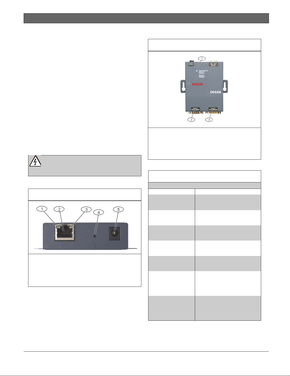
1.1 Network Interface
Figure 1: Power/Ethernet
1- Ethernet Link LED
2- RJ45 Ethernet Jack
3- Ethernet Activity LED
4- Reset Pin
5- Power Plug
1.2 Serial Interface
Figure 2: D6686 Network Interface
1- Power/Diagnostic LEDs
2- Serial Port 2 (DTE) – optional (use
supplied cable if required)
3- Serial Port 1 (DTE) – use supplied null
cable
1.3 LEDs
Table 1: D6686 LEDs
LED Description
Power/Diagnostic
(Blue)
RX Serial 1 Activity
(Green)
TX Serial 1 Activity
(Yellow)
RX Serial 2 Activity
(Green)
TX Serial 2 Activity
(Yellow)
Ethernet Link
(Bi-color LED on left)
Ethernet Activity
(Bi-color LED on right)
Steady On: Power OK
Blinking 2x: No DHCP response
Blinking 2x: Setup Menu active
Off: No data activity
Blinking: Data received by D6686
on Channel 1
Off: No data activity
Blinking: Data transmitted from
D6686 on Channel 1
Off: No data activity
Blinking: Data received by D6686
on Channel 2
Off: No data activity
Blinking: Data transmitted from
D6686 on Channel 2
Off: No Ethernet link established
Solid Yellow: 10 Mbps Ethernet
link established
Solid Green: 100 Mbps Ethernet
link established
Off: No data activity
Solid Yellow: Half Duplex data
activity
Solid Green: Full Duplex data
activity
Bosch Security Systems, Inc. | 10/12 | F01U274796-02
3
Conettix ITS-D6686-UL | Installation Guide | 2.0 Installation
2.2 Mounting the D6686
2.0 Installation
2.1 All Installations
Install the Conettix D6600 Communications
Receiver/Gateway according to NFPA 70, NFPA
72, and the local authority having jurisdiction
(AHJ).
The ITS-D6686-UL is suitable for Central Station
Protective Signaling when it is installed and used
in compliance with NFPA 72 and ANSI/NFPA 70.
Installation limits for digital alarm communicator
receivers (DACR) are under the jurisdiction of the
local AHJ.
The equipment between Ethernet Interface
Modules and the ITS-D6686-UL must be UL
Listed Information Technology Equipment (ITE).
To comply with UL, ensure the following
requirements are met:
• Mount the ITS-D6686-UL, the ITE network
interface equipment, and the D6600 that it is
connected to, in a standard 19-in rack.
• Connect the ITS-D6686-UL to an electrical
outlet located inside the same rack with the
D6686 and D6600.
• Install the ITS-D6686-UL in the same rack as
the D6600 and within 6 m (20 ft) of the
D6600.
• The Ethernet and RS-232 serial cables cannot
exceed 6 m (20 ft) in length.
• Use an uninterrupted power supply (UPS) is
when the ITS-D6686-UL is used for UL Fire
(UL1481) Protective Signaling Systems.
• Use the supplied transformer (Group
West/Part number - 48D-12-900).
Mount the D6686 on a rail or other user-supplied
spot behind the D6600 that it will be connected
to. Refer to Figure 3.
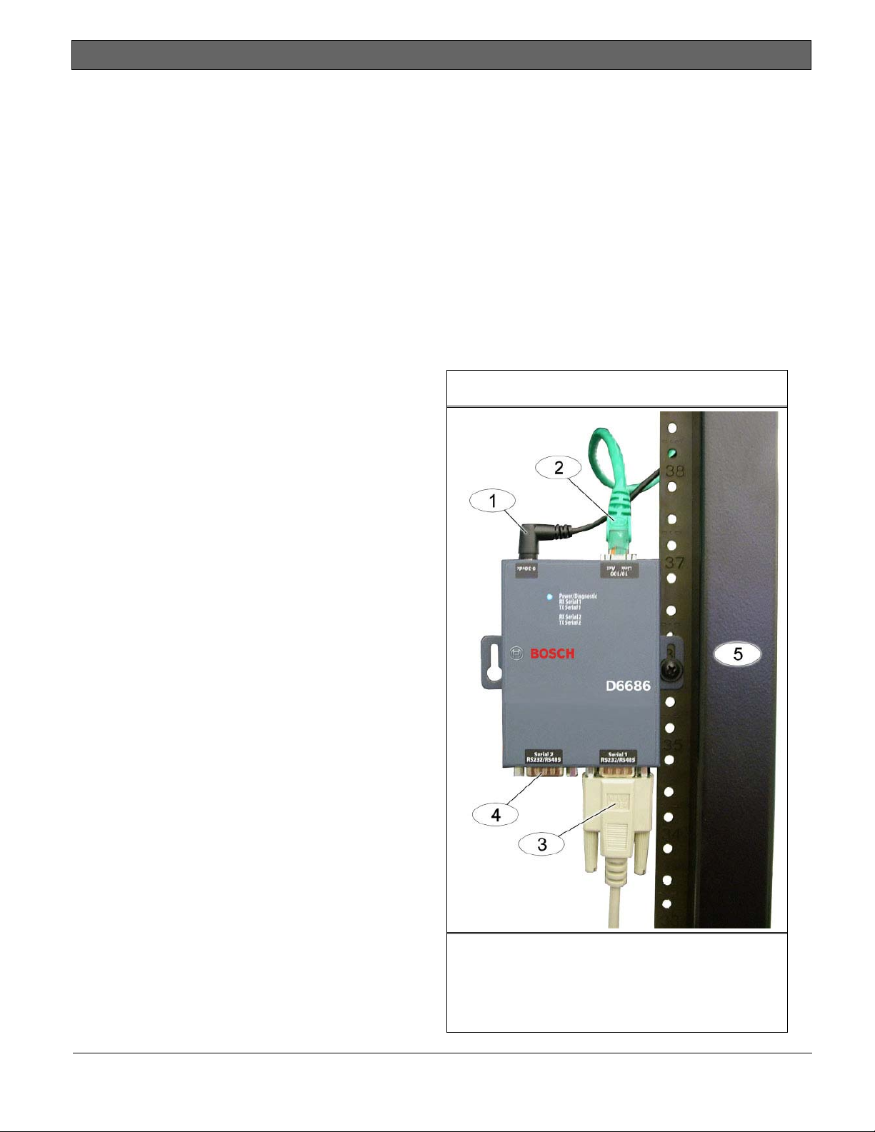
2.3 Connecting the D6686
Connect the D6686 as follows:
• Power cable to an available electrical outlet
• Ethernet cable to network switch
• RS-232 serial cable to Serial 1 port
Refer to the D6600/D6100IPv6 Installation and
Operation Guide – Network Communication
section, (P/N: 4998122704) for applications
using both serial ports.
Refer to Figure 3.
Figure 3: D6686 Connections
4
1– Power cable
2– Ethernet cable
3– RS-232 serial cable (Serial 1 port)
4– Serial 2 port (empty)
5 – Standard 19-in. mounting rack
Bosch Security Systems, Inc. | 10/12 | F01U274796-02
 Loading...