

Bosch ITS-D6682-INTL, ITS-D6682-UL Installation Manual

Conettix ITS-D6682-INTL
Installation Guide
Ethernet Network
EN
Adapter

Conettix ITS-D6682-INTL | Installation Guide | Contents
Contents
1.0 Introduction...................................................... 3
1.1 Network Interface.............................................. 3
1.2 Serial Interface.................................................. 3
1.3 LEDs................................................................. 3
2.0 Installation........................................................ 4
2.1 Mounting the D6682.......................................... 4
2.2 Connecting the D6682 ...................................... 4
3.0 Configuring and Programming the D6682 .... 5
3.1 Factory Default IP Address ............................... 5
3.2 Identifying the MAC Hardware Address ............ 5
3.3 Obtaining an IP Address ................................... 5
3.4 Using ARP to Assign the IP Address ................ 5
3.5 ARP Command Usage...................................... 6
3.6 Using Telnet to Finish the Configuration ........... 7
3.7 Programming Overview for the D6600............ 10
4.0 Specifications ................................................ 11
2 Bosch Security Systems, Inc. | 2/09 | F01U126778-01
Conettix ITS-D6682-INTL | Installation Guide | 1.0 Introduction
.
Trademarks
Microsoft® Windows® 2000, XP, Vista™, and
MS-DOS
trademarks of Microsoft Corporation in the United
States and/or other countries.
®,
are either registered trademarks or
1.0 Introduction
The Conettix D6682 Ethernet Network Adapter is a
two-channel network adapter. Most networked
installations only have one configured channel.
Follow these instructions to avoid the
possibility of harm to the operator, or
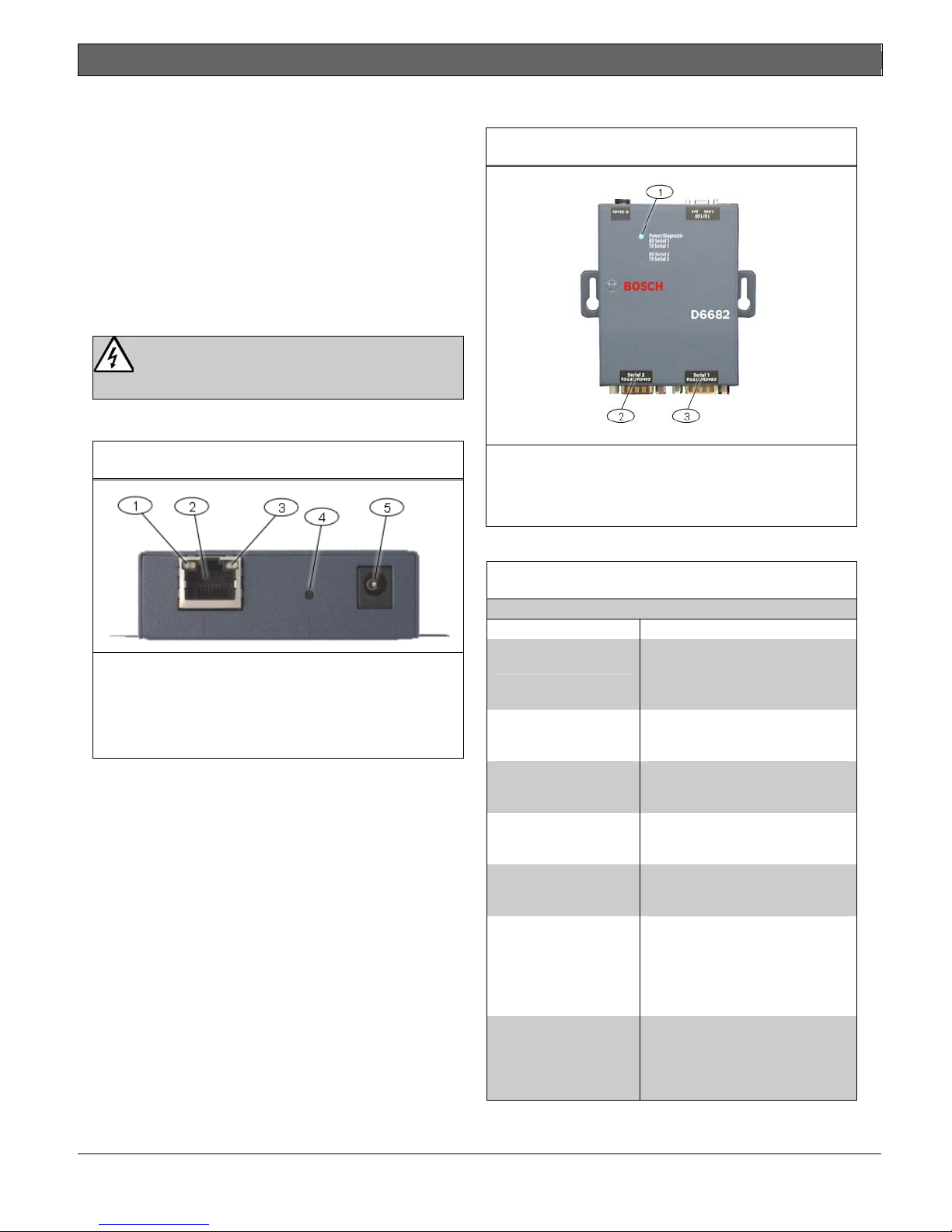
1.1 Network Interface
Figure 1: Power/Ethernet
damage to the equipment.
1.2 Serial Interface
Figure 2: D6682 Network Interface
1- Power/Diagnostic LEDs
2- Serial Port 2 (DTE) – optional (use supplied
cable if required)
3- Serial Port 1 (DTE) – use supplied null cable
1.3 LEDs
1- Ethernet Link LED
2- RJ45 Ethernet Jack
3- Ethernet Activity LED
4- Reset Pin
5- Power Plug
Table 1: D6682 LEDs
LED Description
Power/Diagnostic
(Blue)
RX Serial 1 Activity
(Green)
TX Serial 1 Activity
(Yellow)
RX Serial 2 Activity
(Green)
TX Serial 2 Activity
(Yellow)
Ethernet Link
(Bi-color LED on left)
Ethernet Activity
(Bi-color LED on
right)
Steady On: Power OK
Blinking 2x: No DHCP
response
Blinking 2x: Setup Menu active
Off: No data activity
Blinking: Data received by
D6682 on Channel 1
Off: No data activity
Blinking: Data transmitted from
D6682 on Channel 1
Off: No data activity
Blinking: Data received by
D6682 on Channel 2
Off: No data activity
Blinking: Data transmitted from
D6682 on Channel 2
Off: No Ethernet link
established
Solid Yellow: 10 Mbps
Ethernet link established
Solid Green: 100 Mbps
Ethernet link established
Off: No data activity
Solid Yellow: Half Duplex data
activity
Solid Green: Full Duplex data
activity
Bosch Security Systems, Inc. | 2/09 | F01U126778-01 3
Conettix ITS-D6682-INTL | Installation Guide | 2.0 Installation
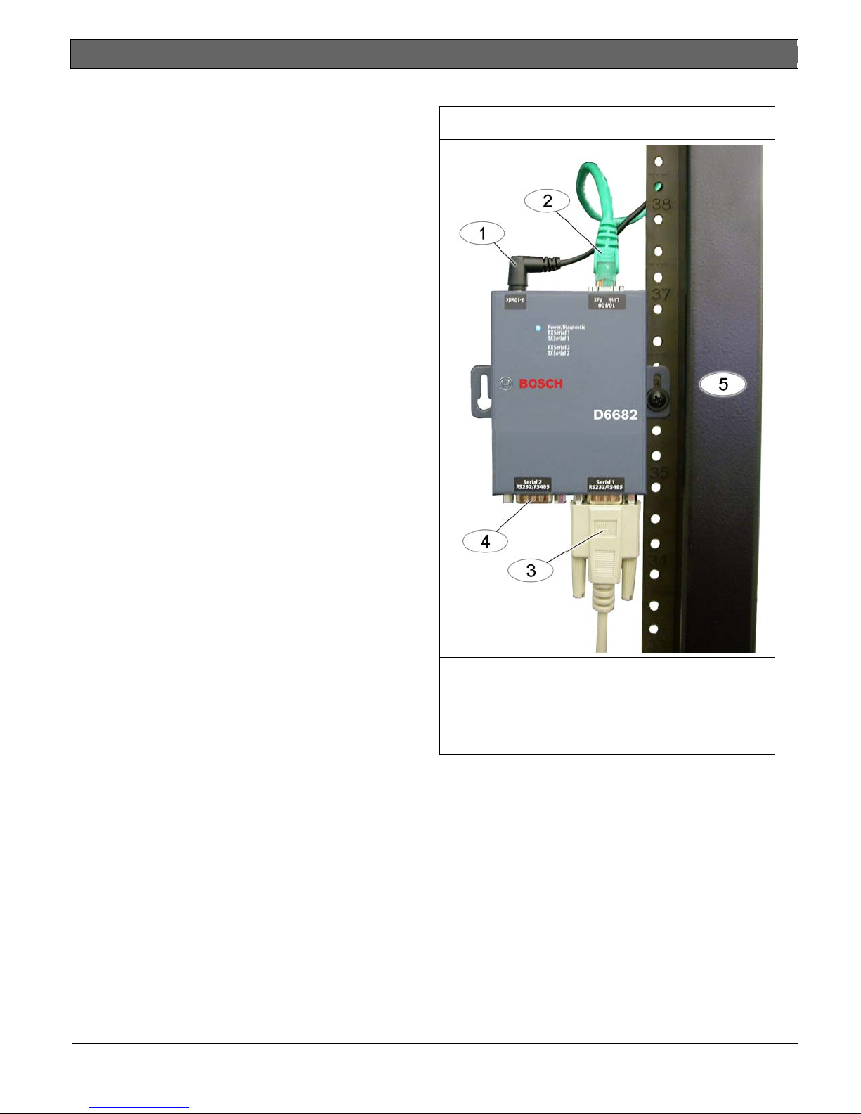
2.0 Installation
Figure 3: D6682 Connections
2.1 Mounting the D6682
Mount the D6682 on a rail or other user-supplied spot
behind the D6600 that it will be connected to. Refer to
Figure 3.
2.2 Connecting the D6682
Connect the D6682 as follows:
• Power cable to an available electrical outlet
• Ethernet cable to network switch
• RS-232 serial cable to Serial 1 port
Refer to the D6600/D6100i System Guide
(P/N: 4998122712) for applications using both
serial ports.
Refer to Figure 3.
4 Bosch Security Systems, Inc. | 2/09 | F01U126778-01
1– Power cable
2– Ethernet cable
3– RS-232 serial cable (Serial 1 port)
4– Serial 2 port (empty)
5 – Standard 19-in. mounting rack
 Loading...