

Bosch ISW-EN4200 Installation Manual
ISW-EN4200 Serial Receiver Installation Guide
Overview
The Bosch Commercial Wireless ISW-EN4200 Serial Receiver,
powered by Inovonics wireless mesh network technology, connects
Commercial Wireless Sensors to supported Bosch control panels via
the ISW-D8125CW-V2 Interface Module.
These instructions cover installation of the ISW-EN4200 Serial
Receiver. For detailed programming instructions, refer to the
ISW-D8125CW-V2 Installation and Operation Guide
(P/N: F01U161691).
1.0 Installation
Use the provided anchors and screws to mount the ISW-EN4200 in
locations accessible for future maintenance.
For best transmitter reception results, place the
ISW-EN4200 in a central location among the transmitters. If
transmitters are too far away for the receiver to pick up the
transmission, install an ISW-EN5040-T Commercial Wireless RF
Repeater.
For UL Listed installations, install the
ISW-D8125CW-V2 Commercial Wireless Interface
Module within 20 ft (6 m) of, and within the same
room as, the ISW-EN4200.
Mount the serial receiver in a location removed from
metal. Metal objects (duct work, wire mesh screens,
boxes) reduce RF range.
2.0 Configuration
Bosch Commercial Wireless products use a range of radio
frequencies and must be configured for your geographic area.
All selection jumpers are shipped in their default positions
(Figure 1). If you want to keep the default selections, setting the
jumpers is not necessary. The ISW-EN4200 ships configured for
North America frequencies.
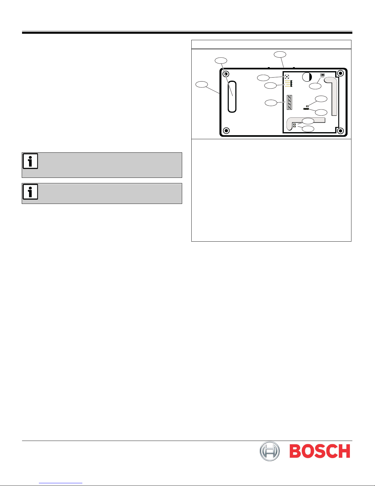
Figure 1: ISW-EN4200 Serial Receiver Components
3
2
4
1
TAMPER
Vs
GND
TX
10
RX
TX
Vs
RXGND
5
6
DEC
NZ AUS
7
8
RX
TX
9
11
1 - Side cabling knockout
2 - Bottom cabling knockout
3 - Housing release tab
4 - Tamper switch
5 - Reset button
6 - DEC (decode) LED
7 - Frequency Band pins:
- No jumper = North America (902 MHz to 928 MHz)
- AUS = Australia (915 MHz to 928 MHz)
- NZ = New Zealand (921 MHz to 928 MHz)
8 - RX (receive) LED
9 - TX (transmit) LED
10 - Serial data terminal
11 - Serial data port
T
To configure the serial receiver:
1. If the serial receiver is powered on, remove the power source
to reset the serial receiver.
2. Use a small screwdriver to press the housing release tab
(Figure 1). Separate the housing.
3. Place a jumper plug on the appropriate Frequency Band pins
(Figure 1). For North America, remove the jumper plug
(default position).
3.0 Wiring Connections
Do not install long cable runs next to high-current
power feeds.
Keep cable lengths as short as possible to minimize
noise pickup.
Measure voltage at the serial receiver on long cable
runs.
To connect the ISW-EN4200 to the ISW-D8125CW-V2:
1. Remove all power from the system (AC and standby battery).
2. Route the cabling through either the bottom cabling knockout
or the side cabling knockout on the ISW-EN4200.
Refer to Figure 1.
3. Connect the serial data terminal block on the ISW-EN4200 to
the data terminal block on the ISW-D8125CW-V2.
Refer to Figure 2 below, or Figure 3 on page 3.
Ensure that the wiring used meets the following specifications:
4. Connect the ISW-D8125CW-V2 to the control panel.
- For all versions of the D7412 and D7212 Control Panels,
you can connect one ISW-D8125CW-V2 Commercial
Wireless Interface Module, and up to two ISW-EN4200
Serial Receivers. Refer to Figure 2 below.
- For all versions of the D9412 Control Panel, and the
D9112 Control Panel, you can connect two
ISW-D8125CW-V2 Commercial Wireless Interface Modules
(one to Zonex 1 and the other to Zonex 2), and up to four
ISW-EN4200 Serial Receivers (two to each
ISW-D8125CW-V2). Refer to Figure 3 on page 3.
- Four-conductor unshielded 20 AWG (or larger)
- Wire length must not exceed 30.5 m (100 ft)
For UL Listed installations, install the ISW-D8125CW-V2
Commercial Wireless Interface Module within 20 ft (6 m)
of, and within the same room as, the ISW-EN4200.
Figure 2: ISW-D8125CW-V2 to D7412 and D7212 (GV3, GV2, and G) Control Panel Wiring Diagram
2
+ AUX POWER
3
9
COMMON
ZONEX OUT 1
ZONEX IN 1
28
27
IN
+12V
ZONEX BUS RECEIVER 2RECEIVER 1
1 - ISW-D8125CW-V2 connected to Zonex 1 on control panel (Points 9 to 127)
2 - Control Panel
3 - ISW-EN4200 Receiver (RECEIVER 1 on ISW-D8125CW-V2)
4 - ISW-EN4200 Receiver (RECEIVER 2 on ISW-D8125CW-V2)
OUT
GND
+12V
TX1
1
RX1
GND
+12V
TX2
RX2
GND
Vs
RX
TX
3
GND
Vs
RX
TX
4
GND
2 | F01U167054-01 | 8/10 ISW-EN4200 Serial Receiver Installation Guide
© 2010 Bosch Security Systems, Inc.
 Loading...