

Bosch ISW-EN1262 Installation Manual
ISW-EN1262 Installation Guide PIR Motion Sensor-Transmitter
Overview
The ISW-EN1262 is a low-current motion detector that is highly
sensitive to moving heat (infrared radiation) sources.
Use the ISW-EN1262 in residential and low-traffic commercial
applications.
1.0 Open the Detector Housing
1. Insert a small flat-blade screwdriver at a 45° angle into the tab
on the bottom of the unit.
2. Press downward on the handle of the screwdriver until the
latch holding the cover to the housing base releases.
Refer to Figure 1.
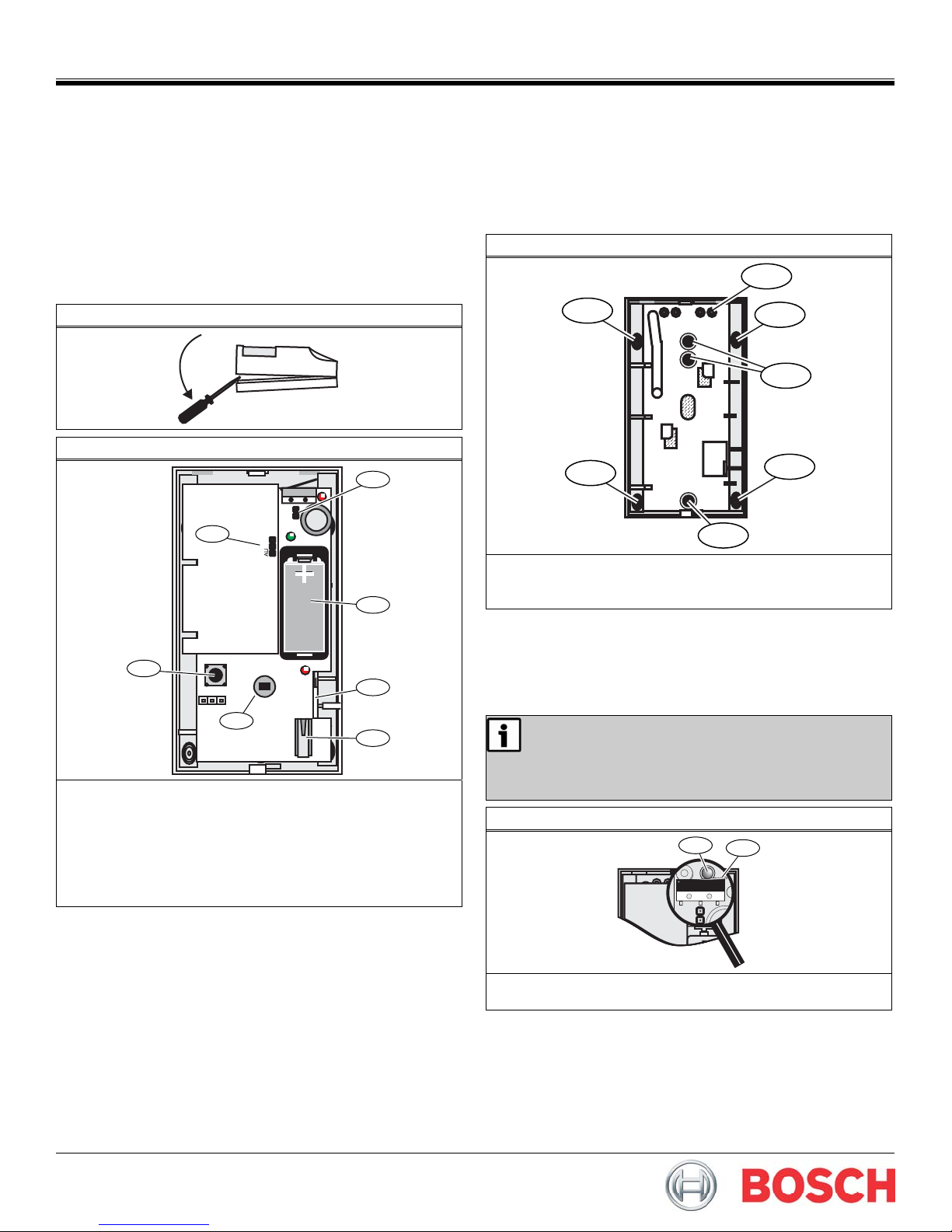
Figure 1: Open the Housing
Figure 2: Detector Components
1
7
NZ
2
6
3
5
4
1 - Wall Tamper pins
2 - Battery
3 - Circuit Board Attachment latch
4 - Housing Tamper switch
5 - Look-down lens
6 - Reset button
7 - Frequency Band pins
2.0 Mount the Housing Back Plate
1. Pull the circuit board attachment latch and lift the circuit board
out of the housing.
Refer to Figure 2.
2. Use a 3/16 in. (4.8mm) bit to drill out the tamper rivet hole
index. Refer to Figure 3 on page 1.
3. Install the tamper wall anchor.
Figure 3: Mounting Holes
1
2
2
3
2
3
1 - Taper rivet hole
2 - Corner- mount hole
3 - Wall mount hole
4. Mount the housing using either the three wall-mount holes or
the four corner-mount holes.
- Use a 4 mm (5/32 in.) bit to drill the appropriate housing
holes.
- Use the included screws to mount the housing.
If using the wall tamper:
- Ensure that the wall tamper rivet depresses the
wall tamper switch. Refer to Figure 4.
- Remove the jumper plug from the wall tamper
Figure 4: Wall Tamper Switch
selection pins. Refer to Figure 2, page 1.
1
2
2
1 - Wall tamper rivet
2 - Wall tamper switch arm
0
2
2
3.0 Select the Frequency Band
Select the appropriate frequency band for your geographic area.
1. Place a selection jumper on the appropriate Frequency Band
pins (refer to Figure 5).
2. Press the Reset button.
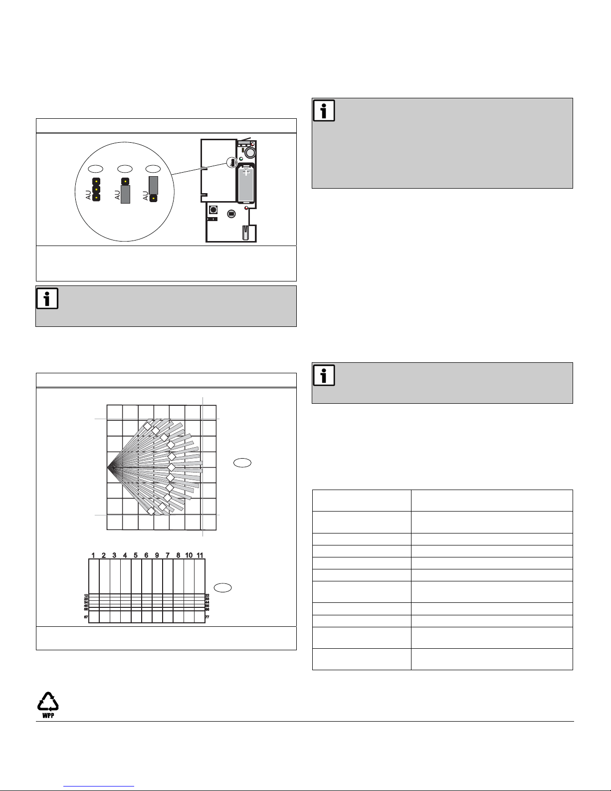
Figure 5: Frequency Band Settings
NZ
NZ
1
NZ
3
2
NZ
1 - North America (902 MHz to 928 MHz) (default)
2 - Australia (915 MHz to 928 MHz)
3 - New Zealand (921 MHz to 928 MHz)
When pressing the Reset button, do not touch the
Frequency Band pins. Touching the Frequency Band
pins while pressing the Reset button can inadvertently
set the detector to the wrong frequency band.
4.0 Mask the Zones
If masking is required, use Figure 6 to mask the appropriate zones.
Use opaque masking material, such as electrical tape.
Figure 6: Mask Zones
40 ft
26 ft
20 ft
12.2 m
14 m
13 ft
0 ft
13 ft
26 ft
2
1
20 ft
4
5
6
7
8
6.1 m
6.1 m
8 m
6 m
4 m
2 m
0 m
2 m
4 m
6 m
8 m
13 ft 26 ft 39 ft
2 m
4 m
0 m
1
2
11
6 m
3
9
10
8 m 10 m 12 m
1 - PIR zone diagram
2 - Lens view diagram
To enable the look-down zones, peel the mask from the look-down
lens. Refer to Figure 2 on page 1 for the location of the look-down
lens.
5.0 Install the Battery
Remove the tab from the battery’s (+) terminal.
Refer to Figure 2, page 1.
The detector must stabilize for at least 3 min after
power-up, at which time the detector is not
operational. During this period, the LED blinks once
per second.
When the 3-min stabilization period ends, the
detector requires a 2-sec quiet period. After the 2-sec
quiet period, the detector enters walk-test mode and
remains in this mode until it detects no motion for
120 sec.
6.0 Register the Transmitter
To ensure that the detector is supervised by the system receiver,
you must register its transmitter with the system receiver. Each
detector has a unique factory-programmed identification number.
Refer to the receiver, network coordinator or control panel
installation instructions for details on registering a transmitter.
1. If necessary, open the detector housing.
2. When prompted to reset the detector, press the Reset button.
Refer to Figure 1 on page 1.
If using the optional housing screws for added security, use a
2.78 mm (7/64 in.) bit to drill out the housing holes on the top
and bottom of the detector housing.
3. Close the detector housing.
7.0 Test the Detector
To ensure correct operation, test the detector after it
registers with the system receiver. To test the
detector, activate each of the conditions and ensure
that an appropriate response occurs.
1. During the 3-min stabilization period, press and release the
housing tamper switch to cause a tamper condition.
Refer to Figure 2, page 1, for the location of the housing
tamper switch.
2. When the stabilization period is complete, replace the housing
cover, and walk in front of the detector to create an alarm.
8.0 Specifications
Dimensions
(H x W x D):
Operating
Temperature:
Humidity: 0 - 90% (non-condensing)
Battery: 3 V lithium (CR123A or DL123A)
Typical Battery Life: 2 years
Tamper: Housing and/or wall tamper (optional)
PIR RF interference
Immunity:
Alarm Lockout Time: 3 min
Mounting Height: 2.1 to 2.7 m (7 to 9 ft)
Standard Lens
Coverage:
Compatible Receivers:
11.4 cm x 6.4 cm x 4.1 cm
(4.5 in. x 2.5 in. x 1.6 in.)
0° C to +60° C (+32° F to +140° F)
Greater than 30 V/m 26 MHz - 1 GHz
12.2 m x 12.2 m (40 ft x 40 ft)
ISW-EN4204R, ISW-EN4216R, and
ISW-EN7280
© Bosch Security Systems, Inc., 2010
130 Perinton Parkway, Fairport, NY 14450 USA
www.boschsecurity.com
F01U126800-03
Installation Guide
05530A
ISW-EN126
4/1
Page 2 of
 Loading...