

Bosch ISW-EN1247 Installation Manual
ISW-EN1247 Installation Guide Glassbreak Sensor-Transmitter
Avoid rooms smaller than 3 x 3 m (10 x 10 ft), such as small
Overview
The ISW-EN1247 is an acoustic glassbreak sensor that transmits
digital RF messages to Bosch Security Systems, Inc. wireless
receivers.
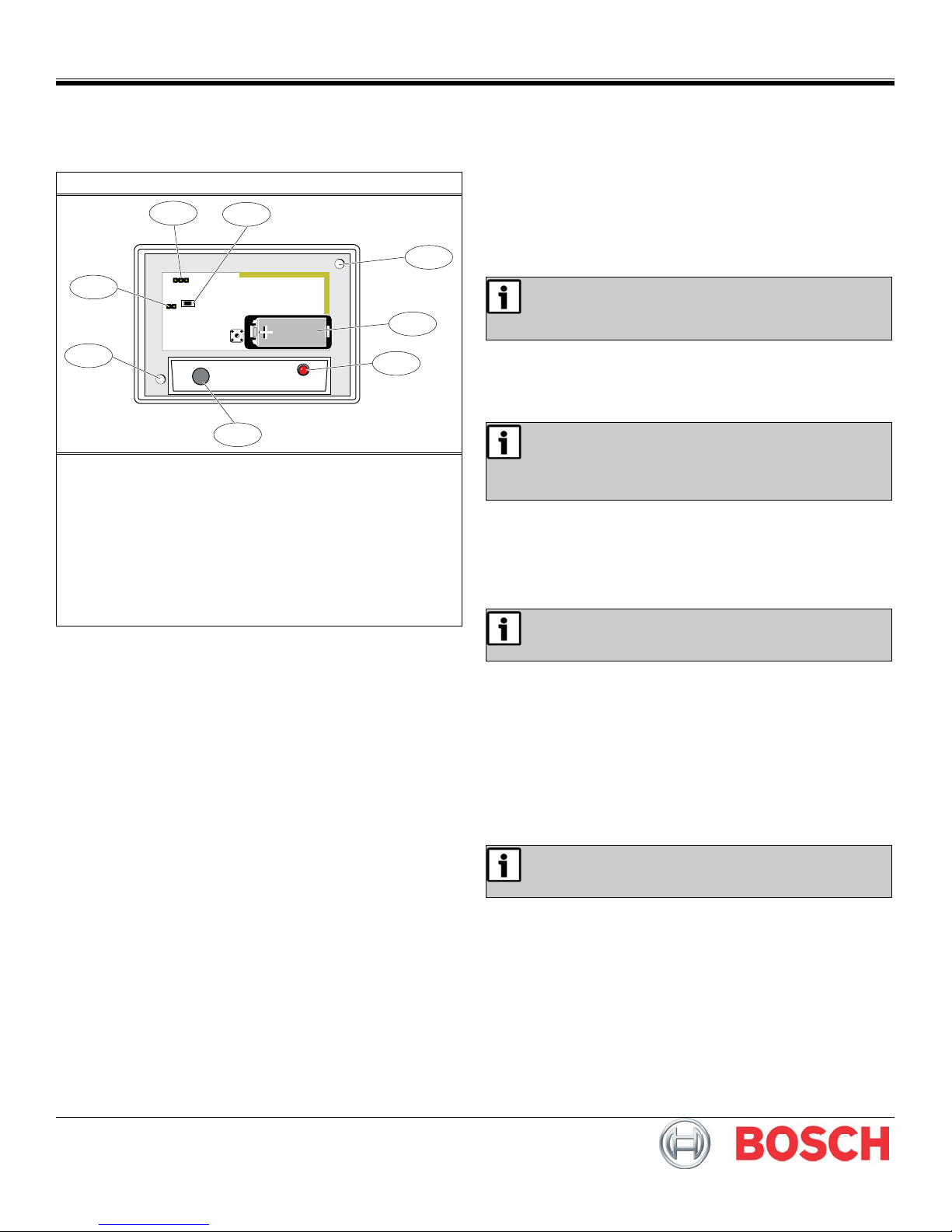
Figure 1: Glassbreak Sensor-Transmitter Components
3
AU NZ
2
RESET
1
4
1
3.0V
5
6
7
1 - Mounting holes
2 - Tamper pins
3 - Frequency Band pins:
No jumper (default) = North America (902 – 928 MHz)
AU = Australia (915 – 928 MHz)
NZ = New Zealand (921 – 928 MHz)
4 - RESET button
5 - 3 V battery
6 - Sensor LED
7 - Microphone
1.0 Mount the Sensor-Transmitter
Use the provided anchors and screws to mount the sensortransmitter, while following these best practices:
•
To avoid false alarms, install the unit as a perimeter zone that
is armed only when the perimeter doors and windows are
armed. Installing the unit as a 24-hour zone can create false
alarms.
Mount the sensor-transmitter at least 0.91 m (3 ft) from the
•
window to be monitored, but no more than 7.62 m (25 ft)
away.
Mount the sensor-transmitter at least 1.2 m (4 ft) away from
•
noise sources (televisions, speakers, sinks, doors, and so on).
•
Mount the sensor-transmitter so that it is in a direct line of
sight of all protected windows.
The best location for mounting the sensor-transmitter is on the
•
opposite wall of the protected window. You can also mount the
sensor-transmitter on the wall adjoining the protected window,
or on the ceiling.
•
The glass should have the following dimensions:
- Dimensions: 0.3 m x 0.6 m (1 x 2 ft) or larger
- Plate thickness: 2.4 mm to 6.4 mm (3/32 to 1/4 in.)
- Tempered thickness: 3.2 mm to 6.4 mm (1/8 to 1/4 in.)
- Wired thickness: 6.4 mm (1/4 in.)
- Laminated thickness: 3.2 mm to 6.4 mm (1/8 to 1/4 in.)
•
Avoid glass airlocks and glass vestibule areas, noisy kitchens
and residential car garages.
•
utility rooms, stairwells, and small bathrooms.
Because the unit is not hermetically sealed, avoid humid
•
rooms.
Avoid rooms where white noise, such as air compressor noise,
•
is present (a blast of compressed air can cause a false alarm).
•
Avoid rooms with noise insulation or sound-deadening drapes,
or with closed wooden interior window shutters.
•
Avoid placing the sensor-transmitter in the corner of a room.
2.0 Select the Frequency Band
The Tamper pins are used to test the sensortransmitter. If the jumper is removed from the Tamper
pins, the unit remains in the tampered state, and does
not function.
Select the appropriate frequency band for your geographic area.
1. Place a selection jumper on the appropriate Frequency Band
pins (refer to
2. Press the RESET button.
Figure 1).
When pressing the RESET button, do not touch the
Frequency Band pins. Touching the Frequency Band
pins while pressing the RESET button can
inadvertently set the detector to the wrong frequency
band.
3.0 Install the Battery
1. Press the housing release tab on the bottom of the sensor-
transmitter’s housing, then pull the housing apart.
2. Install the battery (Figure 1).
3. Press the Reset button to initialize the transmitter.
You must press the RESET button each time you
change the battery.
4.0 Register the Sensor-Transmitter
To ensure that the sensor-transmitter is supervised by the system
receiver, you must register its transmitter with the system receiver.
Each device has a unique factory-programmed identification
number. Refer to the receiver, network coordinator, or control panel
installation instructions for details on registering a transmitter.
1. Open the sensor-transmitter’s housing.
2. When prompted to reset the sensor-transmitter, press the
RESET button (
3. Close the sensor-transmitter’s housing.
Figure 1).
Test the sensor-transmitter after registration to
ensure operation. Refer to Section 5.0 Test the .
5.0 Test the Sensor-Transmitter
Test the sensor-transmitter after installation.
1. Remove the jumper from the Tamper pins to test the
transmitter (
2. To confirm that the sensor has power and the microphone and
circuit board are functioning, clap your hands loudly in front of
the sensor. The LED blinks twice without activating an alarm.
3. For complete testing, use the Sentrol® 5709C Acoustic
Glassbreak Tester to place the unit in Test Mode and simulate
alarm conditions using sonic bursts.
Figure 1). This causes a tamper fault.

6.0 Specifications
Dimensions
(H x W x D):
Typical Battery Life: 2 years
Battery:
Operating Environment:
RF Frequency Range: 902 - 928 MHz
Microphone: Omnidirectional electret
108 x 80 x 43 mm
(4.2 x 3.1 x 1.7 in.)
3.0 V lithium Panasonic® CR123A or
approved equivalent
-20° to 60°C (-4° to 140°F),
noncondensing
Trademarks
Sentrol® is a registered trademark of GE Interlogix in the United
States and/or other countries.
Panasonic® is a registered trademark of Matsushita Electric
Industrial Co., Ltd.
© 2009 Bosch Security Systems, Inc.
130 Perinton Parkway, Fairport, NY 14450-9199 USA
(800) 289-0096
F01U126803-01
Installation Guide
3/09
ISW-EN1247
Page 2 of 2
 Loading...