

Bosch ISW-EN1242 Installation Manual
ISW-EN1242 Installation Guide Smoke Detector-Transmitter
Overview
The ISW-EN1242 Smoke Detector-Transmitter is a wireless, battery-powered
photoelectric smoke sensor. Under non-alarm conditions, the LED flashes
once every 8 sec while the sensor monitors the surrounding conditions. When
the sensor detects smoke, the LED lights, the built-in sounder beeps loudly,
and the detector sends an alarm signal. The smoke sensor is powered by two
3 V lithium batteries.
1.0 Open the Detector-Transmitter Housing
1. Using a small screwdriver, press the sensor cap release tab and turn the
cap approximately 25 mm (1 in.) counter-clockwise to remove the cap
(Figure 1).
Figure 1: Remove the Sensor Cap
2. Place both thumbs on opposite sides of the optical chamber and push
down to detach the sensor housing (Figure 2).
Figure 2: Push Down the Optical Chamber
2.0 Mount the Housing Back Plate
Use the provided anchors and screws to mount the smoke detector, while
following these best practices:
• Install a minimum of two smoke sensors in any household.
• Put a smoke sensor in the hallway outside of every bedroom area.
• Put a smoke sensor on every level of a multi-level residence.
• In rooms with sloped ceilings, install smoke sensors 0.9 m (3 ft)
• Install basement sensors on the ceiling as close to the center of the
• If ceiling mounting is not practical, install the sensor on an inside wall
• Put smoke sensors at both ends of a bedroom hallway if the hallway is
• Areas with rough ceilings or short walls coming down from the ceiling
• Install second-floor smoke sensors on the ceiling at the top of the first-
Do not install sensors:
• On a drop ceiling tile. Mount them on a metal runner.
• In or near areas such as kitchens or garages, where smoke or vehicle
• In damp or very humid areas, or next to bathrooms with showers. Install
• In very cold or very hot areas. Refer to Section 8.0 on page 2 for
• In dusty, dirty, or insect-infested areas.
Regulations pertaining to smoke sensor installations vary. For
more information, contact your local fire department or local
authority having jurisdiction.
measured down from the highest point of the ceiling.
room as possible. If this is not practical, install on the ceiling no closer
than 10 cm (4 in.) from any wall or corner.
between 10 and 15 cm (4 and 6 in.) from the ceiling.
more than 9 m (30 feet) long. Large rooms over 84 square meters (900
square feet) require more than a single sensor.
require additional smoke sensors.
to-second floor stairwell. Ensure that no door or other obstruction
blocks the path of smoke to the sensor.
exhausts normally occur (protect these areas with heat-detection
devices, not with smoke sensors); near furnaces, hot water heaters, or
gas space heaters.
sensors at least 1.5 m (5 ft) away from bathrooms.
operating temperature specifications.
• Near fresh air inlets or returns or excessively drafty areas. Air
conditioners, heater, fans, and fresh air intakes and returns can drive
smoke away from smoke sensors.
• In dead air spaces at the top of a peaked ceiling or a wall or ceiling
intersection. Dead air might prevent smoke from reaching smoke
sensors.
• Near fluorescent light fixtures. Install smoke sensors at least 3 m (10 ft)
away from fluorescent light fixtures.
• Between protruding ceiling structures such as beams or walls which
might prohibit smoke from reaching the sensors.
All sensors are subject to possible compromise or failure-towarn for a variety of reasons. For example, smoke sensors
cannot detect smoke in chimneys, walls, roofs, or smoke
blocked by a closed door; sensors might not detect smoke on
other levels of a building; sensors might not warn in time
when fires are caused by smoking in bed, explosions,
improper storage of flammables, overloaded electrical
circuits, or other hazardous conditions.
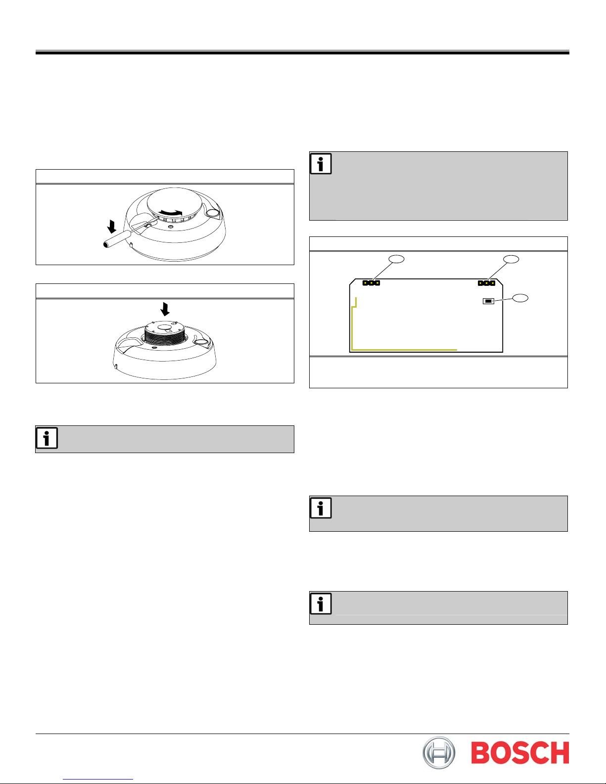
3.0 Configure the Detector
Figure 3: Detector-Transmitter Components
1
LOW BAT CLEAN
2
NZ
AU
3
1 - LOW BAT/CLEAN pins (default = CLEAN)
2 - Frequency Band pins
3 - Reset button
3.1 Select the Frequency Band
Select the appropriate frequency band for your geographic area.
1. Place a selection jumper on the appropriate Frequency Band pins (refer
to Figure 3). The default is no jumper (North America).
• Place the jumper on the left two pins, marked AU, to set the
frequency range to 915-928 MHz for Australia.
• Place the jumper on the right two pins, marked NZ, to set the
frequency range to 921-928 MHz for New Zealand.
• Leave the jumper off the pins to set the frequency range to 902-
928 MHz for North America.
2. Press the Reset button.
When pressing the Reset button, do not touch the Frequency
Band pins. Touching the Frequency Band pins while pressing
the Reset button can inadvertently set the detector to the
wrong frequency band.
3.2 Set Clean/Low Battery Reporting
With the factory default CLEAN setting (refer to Figure 3), the smoke detector
combines the low battery signal with a signal indicating that the detector
needs cleaning. If multiple-condition indication is not desired, disable
wireless reporting of the CLEAN status by moving the jumper to LOW BAT.
With the LOW BAT setting, the detector sends only a low battery signal.
If CLEAN notification is disabled, the sensitivity test still
indicates the sensor condition.
4.0 Install the Battery
1. Rotate the sensor housing counterclockwise approximately 25 mm
(1 in.), and then detach it from the mounting base.
2. Remove the battery compartment cover (Figure 4 on page 2).

9
2
2
Figure 4: Battery Compartment Cover
1
1 - Battery compartment cover
3. Install or replace the two 3 V batteries.
4. Allow up to 10 sec for sensor and transmitter to fully power on before
registration and testing.
5.0 Register the Transmitter
To ensure that the detector is supervised by the system receiver, you must
register its transmitter with the system receiver. Each detector has a unique
factory-programmed identification number. Refer to the receiver, network
coordinator, or control panel installation instructions for details on
registering a transmitter.
1. Open the detector-transmitter housing. Refer to Section 1.0 on page 1.
2. When prompted to reset the detector, press the Reset button. Refer to
Figure 3 on page 1.
3. Close the detector housing.
6.0 Test the Detector
To avoid a fire department dispatch, contact the central
monitoring station or, if possible, put the system into sensor
test mode.
You can test the smoke detector sensor in two ways: the sensitivity test and
the smoke test. Perform the sensitivity test every week, and perform the
smoke test at least once a year. Both tests activate the alarm sounder and
send alarm signals.
The smoke detector should also be tested after initial registration, as well as
each time the smoke chamber is changed or the batteries are replaced.
6.1 Smoke Test
Test smoke sensors annually using aerosol simulated smoke.
The LED illuminates while the built-in transmitter sends an alarm signal, and
the sensor produces a three-beep pattern until you press the Test/Silence
button (Figure 5). The sensor automatically resets when smoke is no longer
present. A sensor that fails to activate might require cleaning. If a sensor still
fails to activate after cleaning, return the unit for service.
Figure 5: Smoke Detector Features
2
1
3
1 - Sounder vent
2 - LED
3 - Test/Silence button
© 2009 Bosch Security Systems, Inc.
130 Perinton Parkway, Fairport, NY 14450-9199 USA
(800) 289-0096
6.2 Sensitivity Test
Press and hold the Test/Silence button for 4 sec, then release it. The LED
flashes correspond to the sensor’s sensitivity.
Flashes Sensor Condition/Action
1 Self-diagnostics failure. Return sensor for service/replacement.
2 - 3
4 - 7 The sensor is within the normal sensitivity range.
8 - 9
During this test, the control panel, serial receiver, or network coordinator
should receive an alarm and a low battery signal (if LOW BAT is selected),
followed a few seconds later by a restoral.
If the control device does not respond, it is possible the smoke detector
failed to reset properly when the batteries were installed. To force a reset,
remove the batteries from the smoke detector for at least 30 sec, reinstall
them, press the RESET button, and then repeat the test as described above.
The sensor is becoming insensitive. Clean the sensor (refer to
Section 7.1) and repeat the test. If the error persists, replace
the sensor.
The sensor is becoming too sensitive. Verify that the smoke
chamber is snapped down securely. Clean the sensor and
repeat the test.
7.0 Operation and Maintenance
Test/Silence button
Status LED
7.1 Clean the Smoke Detector
Clean the sensor cover with a dry or damp cloth as needed to keep it free of
dust and dirt. Clean the sensor interior and replace the optical chamber at
least once each year. Use only ESL Model 211 optical chambers for
replacement. To clean the sensor chamber:
1. Remove the sensor body from the mounting base.
2. Remove the batteries.
3. Slide a flat-blade screwdriver into the slot on the sensor cap and gently
push the handle down to pry the cap off.
4. Squeeze the optical chamber where indicated on the chamber and pull
it up and away from the sensor. Then discard the optical chamber.
5. Use a soft-bristled brush to remove dust and dirt from the smoke
chamber base.
6. Align the new optical chamber with the base and snap it into place.
7. Replace the sensor cap.
8. Reinstall the batteries.
9. Replace the battery cover.
The base does not fit properly if the batteries are not
installed.
10. Reattach the sensor to the mounting base.
11. Perform the sensitivity test. Refer to Section 6.2.
Press to perform the sensitivity test, as well
as to silence the low battery chirp. The low
battery chirp resumes after 24 hours if the
condition is not corrected.
Flashing = The LED flashes every 8 sec to
indicate normal operation
On = Sensor detects smoke, and is sending
an alarm
Off = Maintenance required
8.0 Specifications
Dimensions
(H x W x D):
Operating Temperature: 0°C to 38°C (32°F to 100°F)
Humidity: 10 - 90% (non-condensing)
Battery: (2) 3 V lithium (CR123A recommended)
Transmitter Frequency
Range:
Average Alarm Current: 120 mA
Average Standby Current:
Typical Test Current: 2 mA Low Battery
Chirp Rate: 1 every 45 sec ± 2 sec
UL listings: UL 268, UL 985
F01U126802-02
Installation Guide
Detector: 14.2 cm x 6.1 cm (5.6 in. x 2.4 in.)
Base: 13.7 cm x 1.17 cm (5.4 in. x 0.46 in.)
902 – 928 MHz (United States)
915 – 928 MHz (Australia)
922 – 928 MHz (New Zealand)
35 μA
11/0
ISW-EN124
Page 2 of
 Loading...