

Bosch ISW-EN1235DF, ISW-EN1235SF Installation Manual
ISW-EN1235DF/SF Installation Guide Fixed Location Transmitters
Trademarks
Panasonic is a registered trademark of Matsushita Electric Industrial
Co., Ltd
SANYO is a registered trademark of SANYO North America
Corporation.
Trademark names are used throughout this document. In most
cases, these designations are claimed as trademarks or registered
trademarks in one or more countries by their respective owners.
Rather than placing a trademark symbol in every occurrence of a
trademark name, Bosch Security Systems, Inc. (hereinafter referred
to as Bosch) uses the names only in an editorial fashion and to the
benefit of the trademark owner with no intention of infringing the
trademark.
Overview
The ISW-EN1235DF (double-button) and ISW-EN1235SF (singlebutton) are fixed location transmitters that feature a rugged design
and wall tamper function.
For UL installations, refer to the ISW-EN4216R
Installation Guide (P/N: F01U126806).
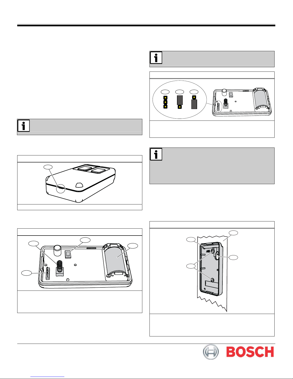
1.0 Open the Transmitter Housing
Insert a small, flat-bladed screwdriver into the housing notch, and
gently pry the housing apart.
Figure 1: Transmitter Housing (ISW-EN1235DF shown)
1
1 - Housing notch
Refer to Figure 2 for component locations.
Figure 2: Transmitter Components
2
1
4
2.0 Select the Frequency Band
Select the appropriate frequency band for your geographic area.
Refer to Figure 3.
If you change the transmitter’s frequency band setting
after initial installation, press the Reset button for the
new setting to take effect.
Figure 3: Frequency Band Settings
1
AUNZ
2
AUNZ
3
AUNZ
1 - North America (902 MHz to 928 MHz) (default)
2 - Australia (915 MHz to 928 MHz)
3 - New Zealand (921 MHz to 928 MHz)
3.0 Mount the Transmitter
• This product is designed to be maintained by
professional security technicians.
• This product is intended for indoor use.
• Manually test this product weekly.
• For UL installations, mount the ISW-EN1235DF/SF
in a concealed area, where operation cannot be
viewed from a public space.
To ensure proper operation, the transmitter must be mounted on a
surface. If the transmitter is not mounted on a surface, it will remain
in a tamper state.
To mount the transmitter:
1. Mount the back plate of the transmitter housing on the
intended surface using the supplied screws.
Refer to Figure 4.
Figure 4: Mounting the Housing Back Plate
1
2
3
1 - Reset button
2 - Wall tamper switch with spring
3 - Frequency band pins
4 - Battery
3
1 - Mounting surface
2 - Transmitter housing back plate
3 - Mounting holes
4 - Hole for wall tamper switch with spring
4
0
F
2
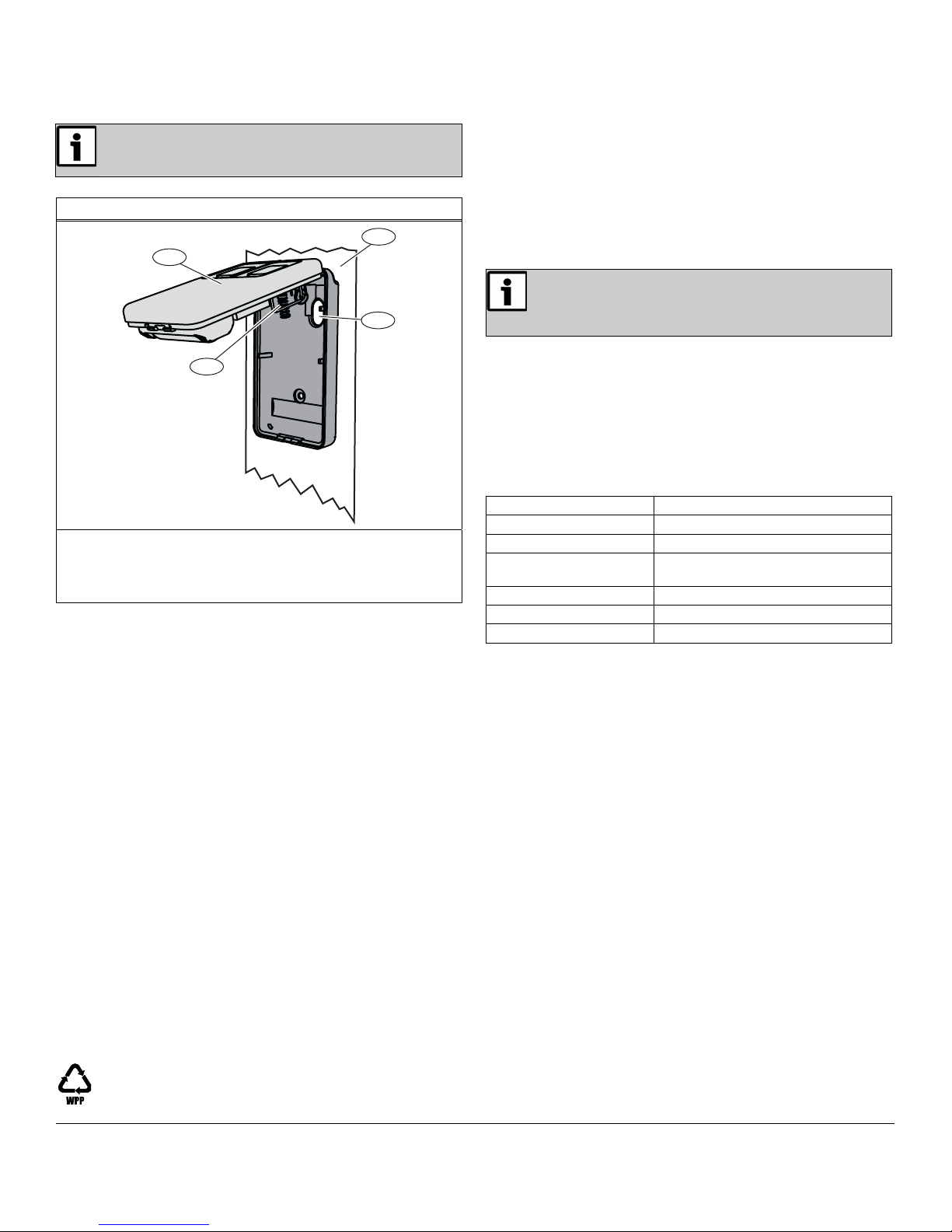
2. Hook the top of the transmitter housing onto the latch on the
top of the back plate. Refer to Figure 5.
Ensure that the spring on the wall tamper switch
makes contact with the mounting surface through the
hole in the back plate.
Figure 5: Mounting Transmitter to the Housing Back Plate
1
2
4
3
1 - Mounting surface
2 - Transmitter housing
3 - Wall tamper switch with spring
4 - Hole for wall tamper switch with spring
3. Clip the transmitter housing in place onto the back plate.
4.0 Install the Battery
1. Install the battery in the location shown in Figure 2.
2. Press the Reset button.
5.0 Register the Transmitter
You must register the transmitter with the system in order for the
transmitter to be monitored and supervised.
When the transmitter is supervised, it sends a check-in message to
the serial receiver or network coordinator every three minutes.
Each transmitter has a unique factory-programmed identification
number. Refer to the receiver’s documentation for details on
registering a transmitter.
When prompted by the receiver to reset the transmitter, press the
reset button on the transmitter. Refer to Figure 2 on page 1.
Test the transmitter after it is registered with the
system.
To test the transmitter, activate each of the
conditions and ensure an appropriate response.
6.0 Operate the Transmitter
To activate or test the single-button transmitter, press and hold the
button. To activate or test the double-button transmitter, press and
hold both buttons.
Alarm signals are sent multiple times and are indicated by the
blinking transmission LED. When the buttons are released, the
transmitter sends an alarm restoral signal
7.0 Specifications
Power Requirement: 3 VDC at 60 mA
Operating Temperature:
Relative Humidity: Up to 90% (non-condensing)
Battery Type:
Typical Battery Life: 3 to 5 years
Compatible Receivers: ISW-EN4216R, ISW-EN7285
UL Listings: UL 365, UL 636, UL 1076, UL 1610
0°C to +60°C (+32°F to +140°F)
Panasonic CR2, Sanyo CR2, or
equivalent
© Bosch Security Systems, Inc., 2010
130 Perinton Parkway, Fairport, NY 14450 USA
www.boschsecurity.com
F01U126794-03
Installation Guide
05522A
ISW-EN1235DF/S
4/1
Page 2 of
 Loading...