

Bosch ISW-EN1215EOL User Manual
ISW-EN1215EOL
Universal Transmitte
r
with Wall Tampe
r
Overview
The ISW-EN1215EOL universal transmitter with an included
wall tamper switch can be used with any standard contact or
sensor. A 2.2 kΩ end of line (EOL) resistor is included with
this transmitter, and is required for operation.
This transmitter includes a back tamper switch. The tamper
condition must be defined within the control panel as a
trouble condition when the system is disarmed, and as an
alarm condition when the system is armed.
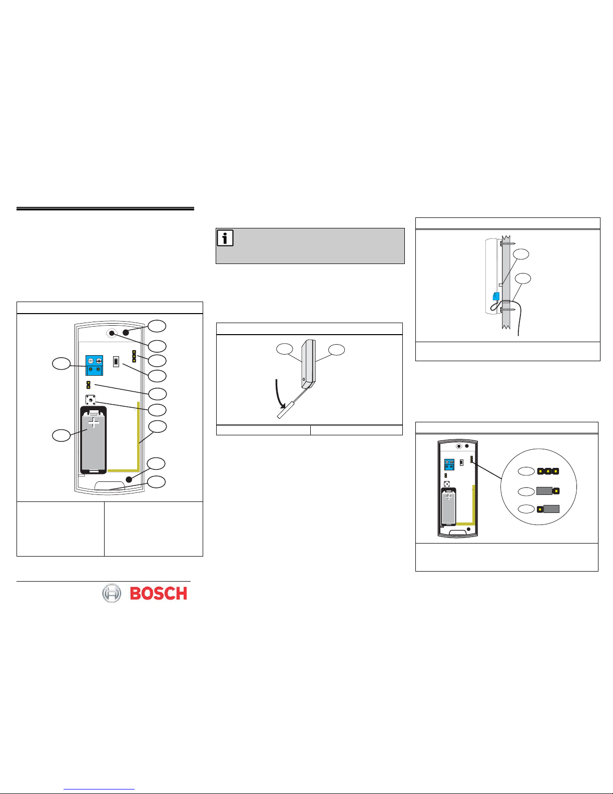
Figure 1: Transmitter Components
••••
RESET
AU NZ
N/O
1
3
4
10
9
5
1
2
6
7
8
1 - Wall-mount screw
holes
2 - Housing screw hole
3 - Frequency Band pins
4 - RESET button
5 - N/O–N/C jumper
6 - Tamper switch with
spring
7 - Antenna
8 - Housing release tab
9 - Battery
10 - Input terminal
1.0 Installation and Startup
• This product is designed to be installed and
maintained by professional security technicians.
• This transmitter is intended for indoor use.
• Manually test this product weekly.
1.1 Open the Housing
1. Use a small flat blade screwdriver to press the housing
release tab on the bottom of the transmitter (refer to
Figure 1).
2. Separate the housing cover from the housing base. Refer
to
Figure 2.
Figure 2: Open the Housing
2
1
1 - Housing cover 2 - Housing base
1.2 Mount the Transmitter
1. Route the external wiring through the wall. Refer to
Figure 3.
2. Mount the transmitter on the wall using the supplied
screws. Refer to
Figure 1 for the wall mount screw hole
locations.
3. Ensure that the housing base is flush against the wall and
the wall tamper switch is firmly pressed.
Figure 3: Mount the Transmitter on the Wall
1
2
1 - Wall tamper switch
2 - External wiring
1.3 Configure the Transmitter
1.3.1 Select the Frequency Band
1. Select the appropriate frequency band for your
geographic area.
2. Place a selection jumper on the appropriate Frequency
Band pins (refer to
Figure 4).
Figure 4: Frequency Band Settings
••••
RESET
AU NZ
N/O
AU NZ
AU NZ
AU NZ
3
2
1
1 - North America (902 MHz to 928 MHz) (default)
2 - Australia (915 MHz to 928 MHz)
3 - New Zealand (921 MHz to 928 MHz)
ISW-EN1215EOL
Universal Transmitte
r
with Wall Tampe
r
©2009 Bosch Security Systems, Inc.
130 Perinton Pkwy, Fairport, NY 14450 USA
(800)289-0096
F01U0126797-01 | 4/09
1.3.2 Select the Input Type and Wire the Resistor
The N/O-N/C pins allow the choice of a normally open (N/O)
or normally closed (N/C) state for the contact circuit wired to
the input terminal.
The transmitter is shipped set for normally closed, with no
selection jumper on the N/O-N/C pins.
If you change the transmitter's input setting after initial
installation, press the RESET button for the new setting to be
effective. Do not touch the Frequency Band pins.
Set for Normally Open Operation
1. Place a jumper on the N/O-N/C pins to select normally
open (N/O).
2. Use 22 AWG wire to connect the 2.2 kΩ resistor in
parallel with the N/O contact (refer to
Figure 5). The
distance from the external contact to the universal
transmitter with wall tamper must not exceed 6.1 m
(20 ft).
Figure 5: Wiring for Normally Open (N/O) Operation
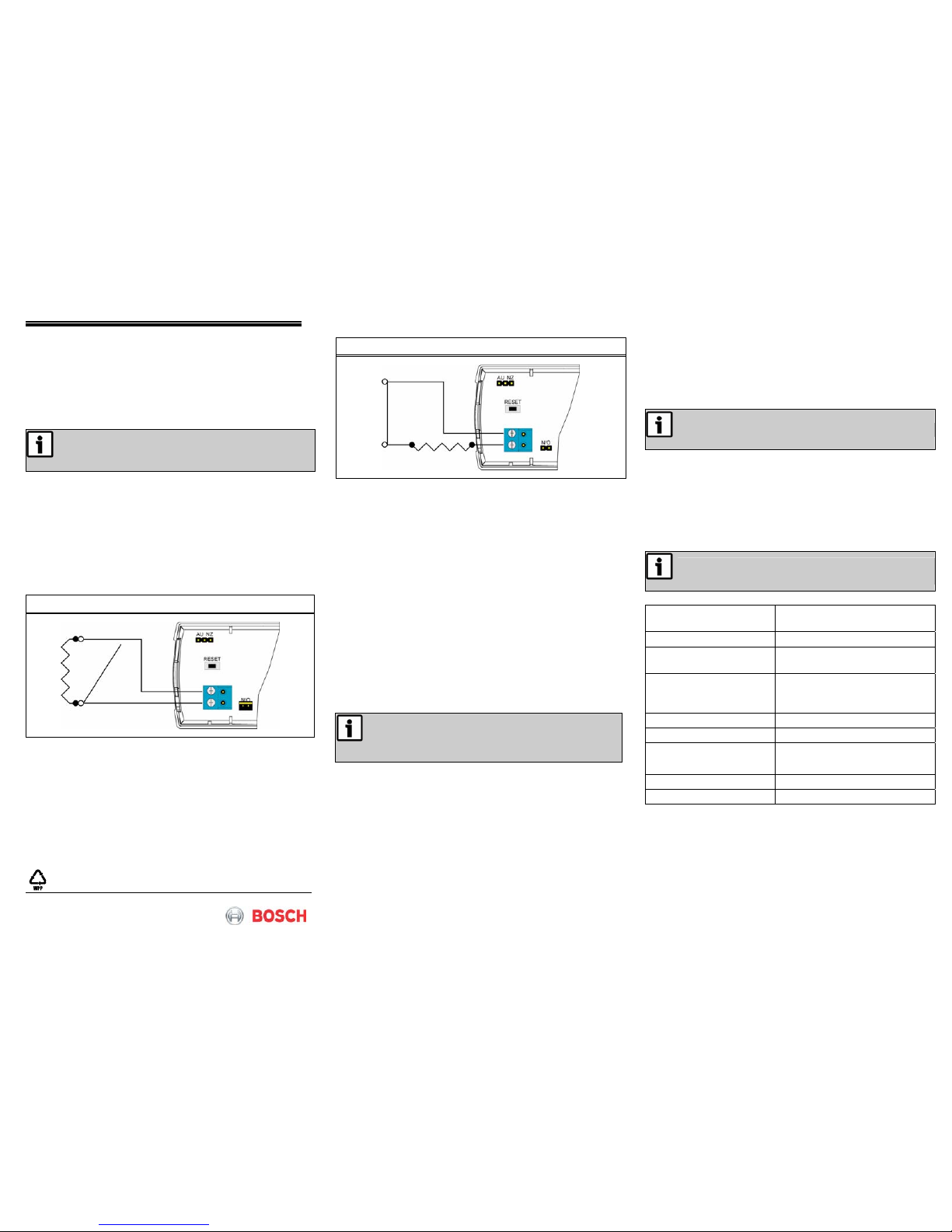
Set for Normally Closed Operation
1. Remove the jumper from the N/O-N/C pins.
2. Use 22 AWG wire to connect the 2.2 kΩ resistor in
parallel with the N/O contact (refer to
Figure 6). The
distance from the external contact to the transmitter
must not exceed 6.1 m (20 ft).
Figure 6: Wiring for Normally Closed (N/C) Operation
1.4 Install the Battery
1. Install the new battery.
2. Press the RESET button to complete the configuration.
Refer to
Figure 1.
2.0 Register the Transmitter
You must register the transmitter with the system in order for
the transmitter to be monitored and supervised. When the
transmitter is supervised, it sends a check-in message to the
serial receiver every three min. Each transmitter has a unique
factory-programmed identification number.
Refer to the receiver’s documentation for details on
registering a transmitter.
1. When prompted by the receiver to reset the transmitter,
press the RESET button on the transmitter (refer to
Figure 1).
When pressing the RESET button, do not touch the
Frequency Band pins. Touching the Frequency Band
pins while pressing the RESET button can inadvertently
set the transmitter to the wrong frequency band.
2. Install the housing cover.
3. Secure the housing cover with a supplied screw inserted
through the housing cover and the housing base (refer to
Figure 1 for the housing screw hole location).
4. Test the transmitter by activating each of the conditions
and ensuring an appropriate response.
3.0 Replace the Battery
1. Remove the housing screw.
2. Remove the housing cover from the housing base.
3. Remove the old battery.
Removing the battery causes a tamper condition.
4. Install the new battery.
5. Press the RESET button to initialize the transmitter. Refer
to
Figure 1.
6. Install the housing cover and the housing screw.
7. Test the transmitter and ensure an appropriate response.
4.0 Specifications
A 2.2 kΩ resistor is required to operate the
EN1215EOL.
Dimensions 89 mm x 43 mm x 23 mm
(3.5 in. x 1.7 in. x 0.9 in.)
Weight 8.5 kg (3 oz)
External contact Normally open (N/O) or
normally closed (N/C)
Distance, external
contact to the universal
transmitter
6.1 m (20 ft) maximum
Power requirement 3 VDC, 60 mA
Typical Battery Life 3 to 5 years
Battery type (BAT604)
Panasonic
®
CR123A or
equivalent
Operating Temperature -20° to +60°C (-4° to +140°F)
Relative humidity Up to 90% (non-condensing)
Trademark
Panasonic® is a registered trademark of Matsushita Electric
Industrial Co., Ltd.
 Loading...