

Bosch IP 3000I IR, IP Micro 3000I, IP Turret 3000I IR, IP 3000I User Manual

FLEXIDOME IP 3000i IR | FLEXIDOME IP micro
3000i | DINION IP 3000i IR | FLEXIDOME IP
turret 3000i IR
NDV‑3502‑F02 | NDV‑3502‑F03 | NDV‑3503‑F02 | NDV‑3503‑F03 |
NTV‑3502‑F02L | NTV‑3502‑F03L | NTV‑3503‑F02L | NTV‑3503‑F03L
| NDE‑3502‑AL | NDE‑3503‑AL | NBE‑3502‑AL | NBE‑3503‑AL
en
User manual


FLEXIDOME IP 3000i IR | FLEXIDOME IP micro
3000i | DINION IP 3000i IR | FLEXIDOME IP turret
3000i IR
Table of contents
Table of contents | en 3
1
Browser connection 5
1.1 System requirements 5
1.2 Establishing connection 5
1.3 Password Network 6
2
System overview 7
2.1 Live page 7
2.2 Playback 7
2.3 Configuration 7
2.4 Dashboard 8
3
Operation via the browser 9
3.1 Live page 9
3.2 Playback page 11
3.2.1 Selecting the recording stream 11
3.2.2 Searching for recorded video 11
3.2.3 Exporting recorded video 12
3.2.4 Track list 12
3.2.5 Controlling playback 12
3.3 Dashboard 12
4
Configuration 14
4.1 General 14
4.1.1 Identification 14
4.1.2 User Management 14
4.1.3 Date/Time 15
4.1.4 Display Stamping 16
4.1.5 GB/T 28181 18
4.2 Web Interface 18
4.2.1 Appearance 18
4.2.2 'Live' functions 20
4.3 Camera 21
4.3.1 Installer Menu 21
4.3.2 Color 25
4.3.3 ALC 25
4.3.4 Enhance 27
4.3.5 Encoder Profile 28
4.3.6 Encoder Streams 29
4.3.7 Encoder Statistics 30
4.3.8 Encoder Regions 30
4.3.9 Privacy Masks 31
4.3.10 Audio 31
4.3.11 Pixel Counter 32
4.4 Recording 32
4.4.1 Storage Management 32
4.4.2 Recording Profiles 34
4.4.3 Maximum Retention Time 35
4.4.4 Recording Scheduler 35
4.4.5 Recording Status 36
4.4.6 Recording Statistics 36
4.4.7 Image Posting 36
Bosch Security Systems B.V. User manual 2019-10 | V01 | DOC

4 en | Table of contents
FLEXIDOME IP 3000i IR | FLEXIDOME IP micro
3000i | DINION IP 3000i IR | FLEXIDOME IP turret
3000i IR
4.4.8 SD Card Status 37
4.5 Alarm 37
4.5.1 Alarm Connections 37
4.5.2 Video Content Analysis (VCA) 39
4.5.3 Audio Alarm 42
4.5.4 Alarm E-Mail 43
4.5.5 Alarm Task Editor 44
4.6 Interfaces 44
4.6.1 Alarm Inputs 44
4.6.2 Alarm Outputs 44
4.7 Network 45
4.7.1 Network Services 45
4.7.2 Network Access 45
4.7.3 DynDNS 47
4.7.4 Advanced 48
4.7.5 Network Management 49
4.7.6 Multicast 50
4.7.7 Accounts 51
4.7.8 IPv4 Filter 51
4.8 Service 52
4.8.1 Maintenance 52
4.8.2 Licenses 53
4.8.3 Certificates 53
4.8.4 Logging 54
4.8.5 System Overview 54
5
Troubleshooting 55
5.1 Physical reset button 55
6
Appendices 56
6.1 Copyright notices 56
2019-10 | V01 | DOC User manual Bosch Security Systems B.V.

FLEXIDOME IP 3000i IR | FLEXIDOME IP micro
3000i | DINION IP 3000i IR | FLEXIDOME IP turret
3000i IR
1 Browser connection
A computer with Microsoft Internet Explorer is used to receive live images, control the unit,
and replay stored sequences. The unit is configured over the network using the browser.
1.1 System requirements
Our recommendations are:
– Computer with Dual core HyperThreading processor or better
– Graphic card with performance that matches or is better than the resolution of the
camera
– Windows7 or later operating system
– Network access
– Internet Explorer version 11 or later
– or –
Application software, for example, VideoSecurityClient, BoschVideoClient or BVMS.
Note:
To see live images in your browser it might be necessary to download and install the MPEGActiveX from the Bosch download store.
Browser connection | en 5
1.2 Establishing connection
The unit must have a valid IP address to operate on your network and a compatible subnet
mask.
By default, DHCP is pre-set at the factory to On plus Link-Local so a DHCP server assigns an
IP address or, if no DHCP server is available, a link-local address (auto-IP) is assigned within
the range 169.254.1.0 to 169.254.254.255.
You can use IP Helper or Configuration Manager to find the IP address. Download the software
from http://downloadstore.boschsecurity.com.
1. Start the Web browser.
2. Enter the IP address of the unit as the URL.
3. During initial installation, confirm any security questions that appear.
Note:
If you cannot connect, the unit may have reached its maximum number of connections.
Depending on the device and network configuration, each unit can have up to 50 web browser
connections, or up to 100 connections via BoschVideoClient or BVMS.
Password protection in the device
The device is password protected across various authorization levels.
You must set a password for the ‘service’ authorization level to get access to the device.
Make sure the password obeys these conditions:
– 8 to 19 characters in length
– Upper and lower case letters
– Minimum of 1 digit
– Minimum of 1 special character
These special characters are not allowed: ‘@’, ‘&’, ‘<’, ‘>’, ‘:’, ‘+’
1. Enter the password in the two text fields.
2. Click Set. If the password is valid, you get access to the device.
Bosch Security Systems B.V. User manual 2019-10 | V01 | DOC

6 en | Browser connection
1.3 Password Network
If a RADIUS server is used for network access control (802.1x authentication), the unit must
be configured first. To configure the unit, connect it directly to a computer using a network
cable and configure the two parameters, Identity and Password. Only after these have been
configured can communication with the unit via the network occur.
FLEXIDOME IP 3000i IR | FLEXIDOME IP micro
3000i | DINION IP 3000i IR | FLEXIDOME IP turret
3000i IR
2019-10 | V01 | DOC User manual Bosch Security Systems B.V.
FLEXIDOME IP 3000i IR | FLEXIDOME IP micro
3000i | DINION IP 3000i IR | FLEXIDOME IP turret
3000i IR
2 System overview
When a connection is established, the Live page is initially displayed.
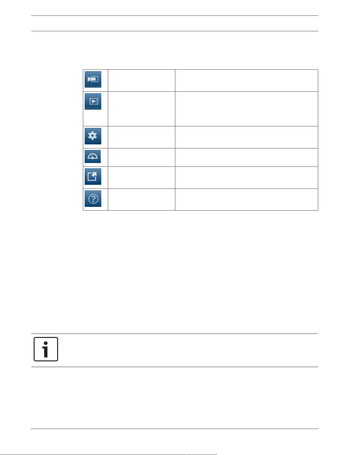
The application bar displays the following icons:
Live Click this icon to view the live video stream.
Playback Click this icon to play back recorded sequences.
Configuration Click this icon to configure the device.
Dashboard Click this icon to see detailed system information.
Links Click this icon to navigate to the Bosch download store.
System overview | en 7
This link is only visible if a storage medium has been
configured for recording. (With VRM recording, this
option is not active.)
2.1 Live page
The Live page is used to display the live video stream and control the unit.
2.2 Playback
The Playback page is used for playing back recorded sequences.
2.3 Configuration
The Configuration page is used to configure the unit and the application interface.
Making Changes
Each configuration screen shows the current settings. You can change the settings by entering
new values or by selecting a predefined value from a list field.
Not every page has a Set button. Changes to pages without a Set button are set immediately.
If a page does show a Set button, you must click the Set button for a change to take effect.
Notice!
Save each change with the associated Set button.
Clicking the Set button saves the settings only in the current field. Changes in any other fields
are ignored.
Click this icon to get context-sensitive help for the page
you are browsing.
Some changes only take effect after the unit is rebooted. In this case, the Set button changes
to Set and Reboot.
1. Make the desired changes.
2. Click the Set and Reboot button. The camera reboots and the changed settings are
activated.
Bosch Security Systems B.V. User manual 2019-10 | V01 | DOC

8 en | System overview
2.4 Dashboard
The Dashboard page is used to display detailed information about the device.
The Dashboard is only visible in the application bar if the Show 'Dashboard' option is enabled
by a service-level user in the Configuration -> Web Interface -> Appearance page.
FLEXIDOME IP 3000i IR | FLEXIDOME IP micro
3000i | DINION IP 3000i IR | FLEXIDOME IP turret
3000i IR
2019-10 | V01 | DOC User manual Bosch Security Systems B.V.

FLEXIDOME IP 3000i IR | FLEXIDOME IP micro
3000i | DINION IP 3000i IR | FLEXIDOME IP turret
3000i IR
3 Operation via the browser
3.1 Live page
After the connection is established, the Live page is initially displayed. It shows the live video
image on the right of the browser window. Depending on the configuration, various text
overlays may be visible on the live video image.
Other information may also be shown next to the live video image. The items shown depend
on the settings on the 'Live' functions page.
Connection
In the Connection group, you can configure the Stream option.
Image selection
To view a live stream:
1. On the left side of the browser, expand the Connection group if necessary.
2. Click the Stream drop-down arrow to see the options.
3. Select the stream you wish to view.
ROI
If Stream 2 is set to SD ROI, the ROI and Pre-positions groups become available.
– Navigate to Configuration -> Camera -> Encoder Streams
– Set Stream 2 to SD ROI
– Click Set to save the settings
– Go back to the Live page
– In the Connection group, click the Stream drop down arrow to see the options
– Select Stream 2
The ROI and Pre-positions groups are now enabled.
To use the ROI functionality, follow these steps:
– On the left side of the browser, expand the ROI group if necessary.
– Use the controls to move around the image.
– Click + to zoom and - to zoom out.
Operation via the browser | en 9
Pre-Positions
Six pre-position files can be defined for views generated by the region of interest (ROI)
controls.
1. On the left side of the browser, expand the Pre-positions group if necessary.
2. Use the ROI controls to define a particular view.
3. To store this view, click the icon of one of the six pre-position buttons.
– If a pre-position is already stored, a dialog box displays a message. Click OK to
overwrite or Cancel to cancel the operation
4. To recall a stored pre-position, click a pre-position button.
Digital I/O
Depending on the configuration of the unit, the alarm input and the output are displayed next
to the image. Expand the Digital I/O group if necessary.
The alarm symbol is for information and indicates the status of an alarm input:
– The symbol lights when the input alarm is active.
The alarm output allows the operation of an external device (for example, a light or a door
opener).
– To activate the output, click the checkmark symbol.
– The symbol lights when the output is activated.
Bosch Security Systems B.V. User manual 2019-10 | V01 | DOC
10 en | Operation via the browser
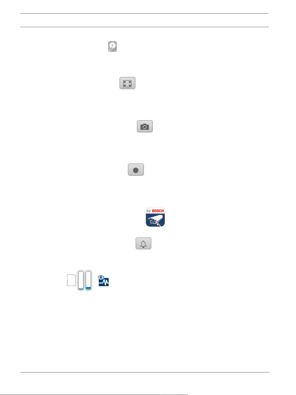
Recording status
The hard drive icon below the live camera image changes during an automatic recording.
The icon lights up and displays a moving graphic to indicate a running recording. If no
recording is taking place, a static icon is displayed.
Full-screen display
Click the full-screen icon to view the selected stream in full-screen mode; press Esc
on the keyboard to return to the normal viewing window.
Saving snapshots
Individual images from the displayed live video stream can be saved locally in JPEG format on
the computer's hard drive. The storage location depends on the configuration of the camera.
– Click the photo camera icon to save a single image.
Recording live video
Video sequences from the displayed live video stream can be saved locally on the computer's
hard drive. The sequences are recorded at the resolution specified in the encoder
configuration. The storage location depends on the configuration of the camera.
FLEXIDOME IP 3000i IR | FLEXIDOME IP micro
3000i | DINION IP 3000i IR | FLEXIDOME IP turret
3000i IR
1. Click the recording icon to record video sequences.
– Saving begins immediately. The red dot on the icon indicates that a recording is in
progress.
2. Click the recording icon again to stop recording.
Start Video Security app
To start the Video Security app, click .
Show latest event
Cick the Show latest event icon to watch the last recorded important events.
The Playback page opens.
Storage, CPU and network status
When accessing the unit with a browser, the local storage, processor and network status
icons are shown in the upper right of the window.
When a local storage card is available, the memory card icon changes color (green, orange or
red) to indicate the local storage activity. If you hover over this icon with the mouse the
storage activity is shown as a percentage.
If you hover over the middle icon, the CPU load is shown.
If you hover over the right-hand icon, the network load is shown.
This information can help with problem solving or when fine tuning the unit. For example:
– if the storage activity is too high, change the recording profile,
– if the CPU load is too big, change the VCA settings,
– if the network load is too big, change the encoder profile to reduce bitrate.
2019-10 | V01 | DOC User manual Bosch Security Systems B.V.
FLEXIDOME IP 3000i IR | FLEXIDOME IP micro
3000i | DINION IP 3000i IR | FLEXIDOME IP turret
3000i IR
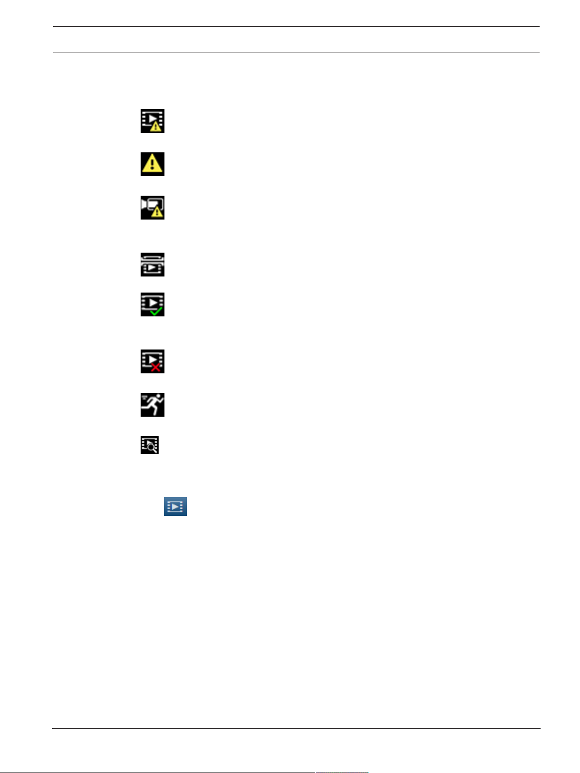
Status icons
Various overlays in the video image provide important status information. The overlays provide
the following information:
Decoding error
The frame might show artifacts due to decoding errors.
Alarm flag
Indicates that an alarm has occurred.
Communication error
A communication error, such as a connection failure to the storage medium, a protocol
violation or a timeout, is indicated by this icon.
Gap
Indicates a gap in the recorded video.
Operation via the browser | en 11
Watermark valid
The watermark set on the media item is valid. The color of the check mark changes according
to the video authentication method that has been selected.
Watermark invalid
Indicates that the watermark is not valid.
Motion alarm
Indicates that a motion alarm has occurred.
Storage discovery
Indicates that recorded video is being retrieved.
3.2 Playback page
Click Playback in the application bar to view, search or export recordings. This link is
only visible when a direct iSCSI or memory card is configured for recording (with Video
Recording Manager (VRM) recording this option is not active).
On the left side of the screen, there are four groups:
– Connection
– Search
– Export
– Track list
3.2.1 Selecting the recording stream
On the left side of the browser, expand the Connection group if necessary.
To view a recording stream:
1. Click the Recording arrow to see the options.
2. Select recording stream 1 or 2.
3.2.2 Searching for recorded video
On the left side of the browser, expand the Search group if necessary.
Bosch Security Systems B.V. User manual 2019-10 | V01 | DOC

12 en | Operation via the browser
1. To limit the search to a particular time range, enter the date and times for the start and
stop points.
2. Select an option from the drop-down box to define a search parameter.
3. Click Search.
4. The results are shown.
5. Click a result to play it back.
6. Click Back to define a new search.
3.2.3 Exporting recorded video
On the left side of the browser, expand the Export group if necessary.
1. Select a track in the track list or in the search results (or click on the timeline below the
video window and drag the buttons to mark the sequence you want to export).
2. The start and stop date and time are filled-in for the selected track. If required, change
the times.
3. In the Time lapse drop-down box, select the original or a condensed speed.
4. In the Location drop-down box, select a target.
5. Click Export to save the video track.
Note:
The target server address is set on the Network / Accounts page.
FLEXIDOME IP 3000i IR | FLEXIDOME IP micro
3000i | DINION IP 3000i IR | FLEXIDOME IP turret
3000i IR
3.2.4 Track list
The Track list shows all the available recordings.
3.2.5 Controlling playback
The time bar below the video image allows quick orientation. The time interval associated with
the sequence is displayed in the bar in gray. Arrows indicate the position of the image
currently being played back within the sequence.
The time bar offers various options for navigation in and between sequences.
– If required, click in the bar at the point in time at which the playback should begin.
– Change the time interval displayed by clicking the plus or minus icons or use the mouse
scroll wheel. The display can span a range from six months to one minute.
– Click the alarm jump buttons to go from one alarm event to the next or to the previous
one. Red bars indicate the points in time where alarms were triggered.
Controls
Control playback by means of the buttons below the video image.
The buttons have the following functions:
– Start/Pause playback
– Select the playback (forward or backward) speed using the speed regulator
– Step forward or backward frame-by-frame when paused (small arrows)
3.3 Dashboard
The Dashboard page shows information on 4 topics:
– Device status
– Recording status
– Connection Status
– Services
You can also download a .JSON file with information about the device:
1. At the bottom of the page, locate the Export button
2. Click the Export button
2019-10 | V01 | DOC User manual Bosch Security Systems B.V.

FLEXIDOME IP 3000i IR | FLEXIDOME IP micro
3000i | DINION IP 3000i IR | FLEXIDOME IP turret
3000i IR
3. Select a location in your hard drive to store the file
Operation via the browser | en 13
Bosch Security Systems B.V. User manual 2019-10 | V01 | DOC

14 en | Configuration
4 Configuration
4.1 General
4.1.1 Identification
Device name
Assign a unique name to assist in identification. This name simplifies the management of
multiple devices in more extensive systems.
The name is used for remote identification, for example, in the event of an alarm. Choose a
name that makes it as easy as possible to identify the location unambiguously.
Device ID
Each device should be assigned a unique identifier that can be entered here as an additional
means of identification.
Each video channel can be given a name. Click the + sign to add an extra line.
Initiator extension
Add text to an initiator name to make identification easier in large iSCSI systems. This text is
added to the initiator name, separated from it by a full stop. (You can see the initiator name in
the System Overview page.)
FLEXIDOME IP 3000i IR | FLEXIDOME IP micro
3000i | DINION IP 3000i IR | FLEXIDOME IP turret
3000i IR
Click Set to apply the changes.
4.1.2 User Management
A password prevents unauthorized access to the device. You can use different authorization
levels to limit access.
Proper password protection is only guaranteed when all higher authorization levels are also
protected with a password. Therefore, you must always start from the highest authorization
level when assigning passwords.
You can define and change a password for each authorization level if you are logged into the
“service” user account.
Authentication modes
The section Authentication modes provides information about the authentication modes set
in the camera. A checkmark appears in the checkbox to the left of the mode if the mode is set.
If the mode is not set, the phrase “No certificate installed” appears to the right of the mode
name.
This device has three authentication modes:
– Password indicates a password is set for the camera. It prevents unauthorized access to
the device, and can use different authorization levels to limit access.
Proper password protection is only guaranteed when all higher authorization levels are
also protected with a password. Therefore, you must always start from the highest
authorization level when assigning passwords.
You can define and change a password for each authorization level if you are logged into
the service user account.
– Certificate. A check mark in this check box indicates that at least one certificate is loaded
onto the device.
The Trusted certificate is a root certificate for Bosch Security Systems that proves that
the device meets the following criteria:
– It originates from a Bosch factory that is a secure environment.
– It has not been tampered with.
The Trusted certificate is issued by Escrypt. Escrypt is a Bosch company and Certificate
Authority (CA).
2019-10 | V01 | DOC User manual Bosch Security Systems B.V.

FLEXIDOME IP 3000i IR | FLEXIDOME IP micro
3000i | DINION IP 3000i IR | FLEXIDOME IP turret
3000i IR
– Active Directory server (AD FS). A check mark in this check box indicates that the device
uses an active directory server.
Creating a new user
To create a new user, click Add in the section below Authentication modes.
In the box User, fill in the fields:
1. User name: Enter a name with a minimum of 5 and a maximum of 31 characters.
2. Group, select the appropriate authorization level:
– live is the lowest authorization level. At this level, it is only possible to view the live
video image, and switch between the different live image displays.
– user is the middle authorization level. At this level, it is possible to operate the
device and playback recordings, but configuration changes are not possible.
– service is the highest authorization level. Entering the correct password gives access
to all the functions, and allows all configuration settings to be changed.
3. Type, select either:
– Password for a new password.
Use a minimum of 8 and a maximum of 19 characters. The password must have
upper-case and lower-case letters, one or more numerical digits and one or more of
these special characters ! ? ” # $ % ( ) { } [ ] * - = . , ; ^ _ | ~ \
Special characters such as space @ : < > ‘ & + are not valid.
In this case, enter the new password a second time to eliminate typing mistakes.
– Certificate for a certificate that the new user is authorized to use.
4. Click Set to confirm and create a new user.
Configuration | en 15
4.1.3 Date/Time
Date format
Select the required date format.
Device date/Device time
If there are multiple devices operating in your system or network, it is important to
synchronize their internal clocks. For example, it is only possible to identify and correctly
evaluate simultaneous recordings when all devices are operating on the same time.
1. Enter the current date. Since the device time is controlled by the internal clock, it is not
necessary to enter the day of the week – it is added automatically.
2. Enter the current time or click Sync to PC to apply the system time from your computer
to the device.
Note:
It is important that the date/time is correct for recording. An incorrect date/time setting could
prevent correct recording.
Device time zone
Select the time zone in which the system is located.
Daylight saving time
The internal clock can switch automatically between normal and daylight saving time (DST).
The unit already contains the data for DST switch-overs for many years in advance. If the date,
time and zone have been set up correctly, a DST table is automatically created.
If you decide to create alternative daylight saving time dates by editing the table, note that
values occur in linked pairs (DST start and end dates).
Bosch Security Systems B.V. User manual 2019-10 | V01 | DOC

16 en | Configuration
FLEXIDOME IP 3000i IR | FLEXIDOME IP micro
3000i | DINION IP 3000i IR | FLEXIDOME IP turret
3000i IR
First, check the time zone setting. If it is not correct, select the appropriate time zone and
click Set.
1. Click Details to edit the DST table.
2. Click Generate to fill the table with the preset values from the unit.
3. Click one of the entries in the table to make changes. The entry is highlighted.
4. Click Delete to remove the entry from the table.
5. Choose other values from the list boxes under the table, to change the selected entry.
Changes are immediate.
6. If there are empty lines at the bottom of the table, for example after deletions, add new
data by marking the row and selecting values from the list boxes.
7. When finished, click OK to save and activate the table.
Time server address
The unit can receive the time signal from a time server using various time server protocols and
then use it to set the internal clock. The device polls the time signal automatically once every
minute.
Enter the IP address of a time server.
Overwrite by DHCP
Select this checkbox to have the DHCP server give the time server date.
Time server type
– Select Time protocol if the server uses the RFC 868 protocol.
– Select the protocol that is supported by the selected time server. It is recommended to
select the SNTP protocol protocol. This protocol provides high accuracy and is required
for special applications and future function extensions.
– Select the TLS protocol if the server uses the RFC 5246 protocol.
Click Set to apply the changes.
4.1.4 Display Stamping
Various overlays or stamps in the video image provide important supplementary information.
These overlays can be enabled individually and arranged on the image in a clear manner.
Camera name stamping
Select the position of the camera name overlay in the drop-down box. It can be displayed at
the Top, at the Bottom, or at a position of choice using the Custom option, or it can be set to
Off for no overlay information.
If the Custom option is selected, enter values in the X and Y position fields.
Optionally, tick the Underlay with full-width black bar box to place a black bar beneath the
time stamp.
Logo
To place a logo on the image, select and upload an uncompressed .bmp file with a maximum
size of 300x300 pixels and 256 colors to the camera. Its position on the image can then be
selected.
Logo position
This option becomes available when the Camera name stamping option is enabled. Select:
– Off : This option is disabled.
– To the left of the name: The logo will be positioned to the left of the Camera name
stamping
– To the right of the name: The logo will be positioned to the right of the Camera name
stamping
2019-10 | V01 | DOC User manual Bosch Security Systems B.V.

FLEXIDOME IP 3000i IR | FLEXIDOME IP micro
3000i | DINION IP 3000i IR | FLEXIDOME IP turret
3000i IR
– Logo only: The logo will be shown without the Camera name stamping.
Time stamping
Select the position of the time and date overlay in the drop-down box. It can be displayed at
the Top, at the Bottom, or at a position of choice using the Custom option, or it can be set to
Off for no overlay information.
If the Custom option is selected, enter values in the X and Y position fields.
Display milliseconds
If necessary, display milliseconds for Time stamping. This information can be useful for
recorded video images; however, it does increase the processor's computing time. Select Off
if displaying milliseconds is not needed.
Live video indicator
Select On to display the Live video indicator, an icon that pulses on the OSD to show that the
video stream is live.
Select Off to hide the Live video indicator.
Alarm mode stamping
Select On in the drop-down box for a text message to be displayed in the event of an alarm. It
can be displayed at a position of choice using the Custom option, or it can be set to Off for no
overlay information.
If the Custom option is selected, enter values in the X and Y position fields.
Configuration | en 17
Alarm message
Enter the message to be displayed on the image in the event of an alarm. The maximum text
length is 31characters.
Transparent background
Check this box to make transparent the stamp background on the image.
Text color
Select the color for the alarm message to be displayed in.
Background color
Select the background color for the alarm message to be displayed in.
If you have enabled the Transparent background option, the background color is not
displayed in the OSD.
Stamping size
Select the desired font size of the overlays on the OSD: Normal or Large.
Video authentication
Select from the Video authentication drop-down box a method for verifying the integrity of
the video.
If you select Watermarking, all images are marked with an icon. The icon indicates if the
sequence (live or saved) has been manipulated.
If you want to add a digital signature to the transmitted video images to ensure their integrity,
select one of the cryptographic algorithms for this signature.
Signature interval [s]
For certain Video authentication modes, enter the interval (in seconds) between insertions of
the digital signature.
Click Set to apply the changes.
Bosch Security Systems B.V. User manual 2019-10 | V01 | DOC

18 en | Configuration
4.1.5 GB/T 28181
This page allows you to set the parameters for conformance to the GB/T28181 national
standard “Security and protection video monitoring network system for information transport,
switch and control”. This standard is specifically for China.
Enable
Select this checkbox to enable the system to use the other parameters on this page in
accordance with the GB/T 28181 national standard.
H.264 elementary stream
Select this checkbox to select or to enable the H.264 elementary stream.
Registration timeout
Enter a value (in milliseconds) for the registration timeout. The default is 3600.
Heartbeat timeout
Enter the value (in seconds) for the heartbeat timeout. The default is 15.
Server ID
Enter the ID of the server.
Server IP address
Enter the server IP address.
Server port
Enter the number of the server port. The default is 0.
FLEXIDOME IP 3000i IR | FLEXIDOME IP micro
3000i | DINION IP 3000i IR | FLEXIDOME IP turret
3000i IR
Device ID
Enter the ID of the device.
Device port
Enter the number of the device port. The default is 5060.
Password
Enter the appropriate password.
Alarm device ID
Enter the ID of the alarm device.
Click Set to apply the changes.
4.2 Web Interface
4.2.1 Appearance
You can adapt the appearance of the web interface and change the website language to meet
your requirements.
GIF or JPEG images can be used to replace the company and device logos. The image can be
stored on a web server (for example, http://www.myhostname.com/images/logo.gif).
Ensure that a connection to the web server is always available to display the image. The image
files are not stored on the unit.
To restore the original graphics, delete the entries in the Company logo and Device logo
fields.
Website language
Select the language for the user interface.
Company logo
To replace the company's logo in the top-right part of the window, enter the path to a suitable
image in this field. The image file must be stored on a web server.
2019-10 | V01 | DOC User manual Bosch Security Systems B.V.
 Loading...