

Bosch HUMBSBP-12H6--A, HUMBLBP-17H6--A Installation And Maintenance Manual
Installation and Maintenance Manual
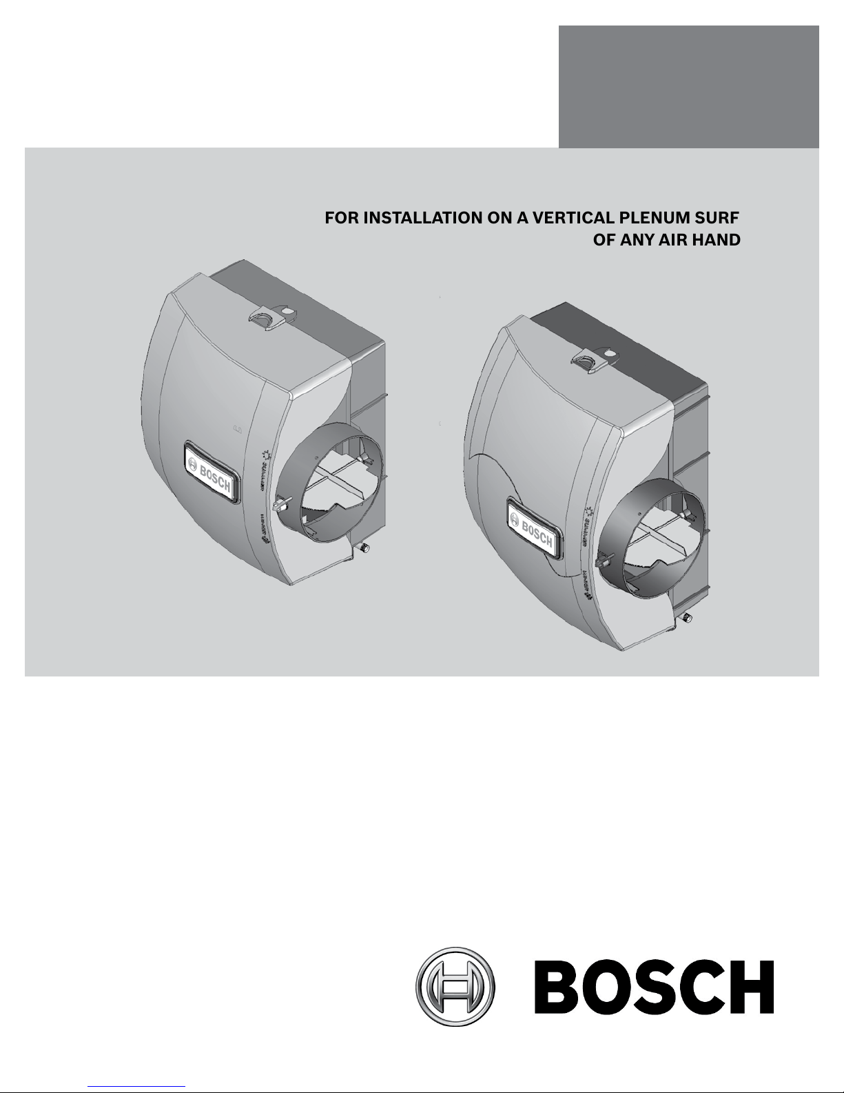
FLOW-THROUGH BYPASS HUMIDIFIER
FOR INSTALLATION ON A VERTICAL PLENUM SURFACE
IAQ Series
OF ANY AIR HANDLER
HUMBSBP-12H6--A
HUMBLBP-17H6--A
6 720 220 343 Revised 07-12

2 IAQ Series Table of Contents
TABLE OF CONTENTS
Installation ....................................................................................... 3
Additional Materials That May Be Necessary ................................ 3
Humidity Control Humidistat HUMB-TST-A-A .................................... 5
Safety .............................................................................................. 5
Application ....................................................................................... 5
Operation ........................................................................................ 5
Installation Instructions—Precautions .............................................. 5
Wall Mount Instructions—Humidistat/Dehumidistat Versions ........... 5
Duct Mounting on the Return Air—Wall Base ..................................... 6
Duct Mounting on the Return Air—Duct Base .................................... 6
HUM-TST-H-A Calibration Instructions ............................................. 7
Wiring .............................................................................................. 7
Checkout ......................................................................................... 7
Settings ........................................................................................... 7
Care and Maintenance ..................................................................... 7
How the Humidier Works ............................................................... 8
Humidier Packaged Component Accessories ................................. 8
Contact your local Bosch Dealer or Installing Contractor
for product support ...................................................................... 8
Heat Pump Wiring Diagram .............................................................. 9
Alternate Electrical & Control Connections .................................... 10
Parts List for Humidier ................................................................. 11
Bosch Humidier Specications .................................................... 11
Humidier Dimensional Drawings .................................................. 12
Troubleshooting ............................................................................. 13
Product Limited Warranty .............................................................. 14
6 720 220 343
Subject to change without prior notice Revised 07-12
Installation IAQ Series 3
The installer should be an experienced service
technician. Disconnect electrical power before
beginning installation. Do not install where
temperatures fall below 32 degrees F or where
plenum temperatures exceed 150 degrees F.
When wiring into a multi-speed blower circuit
see Step 6.
INSTALLATION
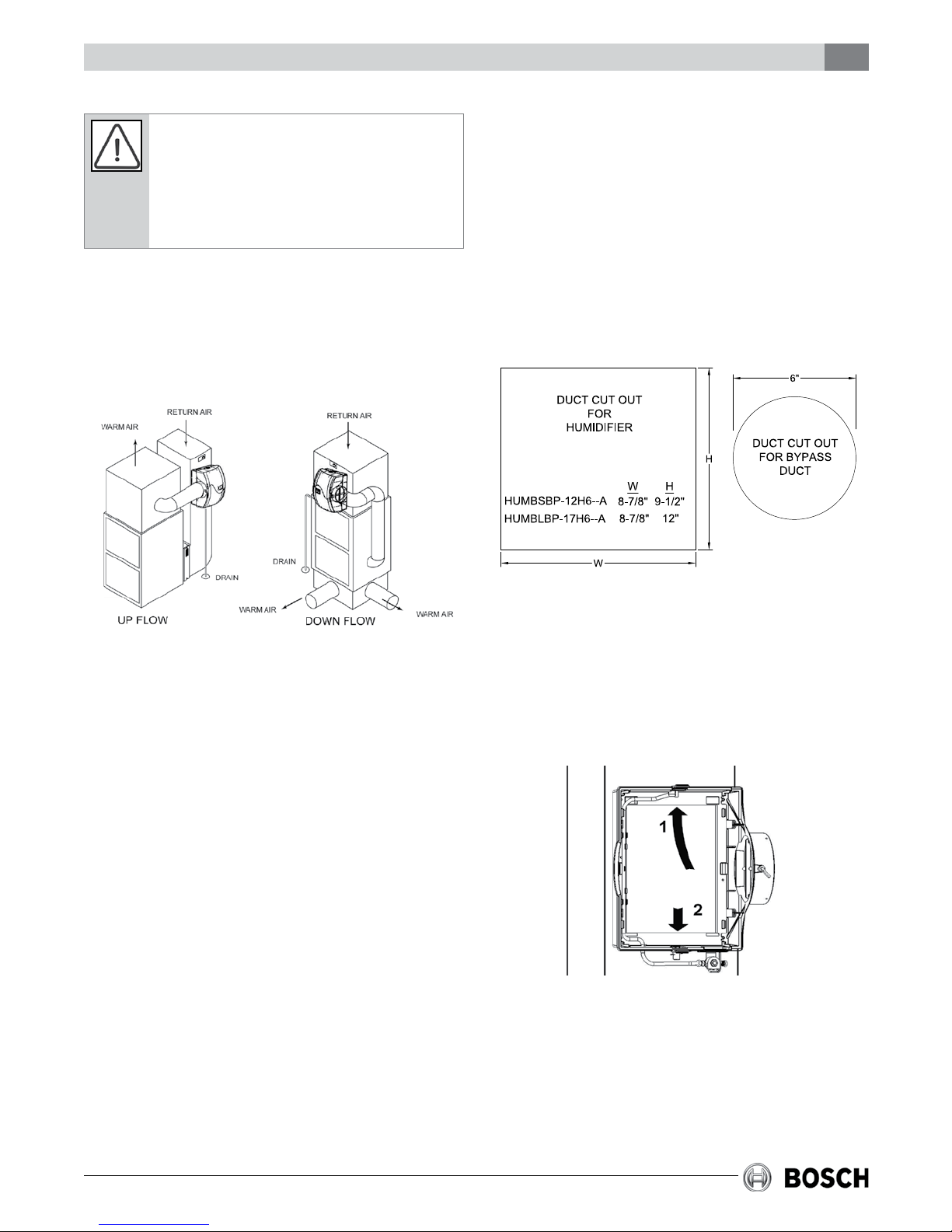
The humidier may be mounted with the 6” outlet to
the right or left side. The humidier may be mounted
on the warm or return air plenum with equal
efciency. See Typical Installations.
Step 2: The BOSCH humidier may be installed on
either the supply or return plenum of a forced air
handling system. Select a location for the humidier
that allows for service and maintenance. Cut out a
rectangle. Extend horizontal center line of cut out to
the adjacent plenum. Cut a 6” hole 10” to 15” from
side of humidier, on cabinet center line, using
connecting collar as guide. The bypass is reversible
and can be mounted on the right or left side of the
humidier. Use provided template provided in the
humidier package. See Figure 1.
Additional Materials That May Be
Necessary
1. 1/4” diameter plastic supply tubing or 1/4”
copper supply tubing for hot water applications
2. 6” diameter galvanized by-pass pipe
3. Electrical wire and wire nuts
4. Current sensing relay
5. #8 self piercing sheet metal screws
6. Accurate Humidity measuring device.
STEP 1: Carefully unpack the Bosch Humidier and
verify that all contents are present and undamaged.
Remove the cover using the the release tabs on the
top and bottom, exposing the humidier evaporator
pad. Remove the evaporator pad, drain pan, and
distributor trough ( all of this should come out as
one piece).
Figure #1
Step 3: Humidier is self retaining. Slide top side in
rst, then slide chassis down. Level chassis and
install center screws. If by-pass duct installs to
opposite side of chassis, bend clip on chassis,
remove side discharge, and reinstall discharge to
opposite side of chassis. Install remaining four
corner screws. See Figure 2.
Figure #2
Step 4: Connect by-pass duct to collar and
humidier cabinet. Using holes at top and bottom of
side panel discharge, pierce 2 self tapping screws
through by-pass pipe. See Figure 3.
Revised 07-12 Subject to change without prior notice
6 720 220 343
1
2
4 IAQ Series Installation
Figure #3
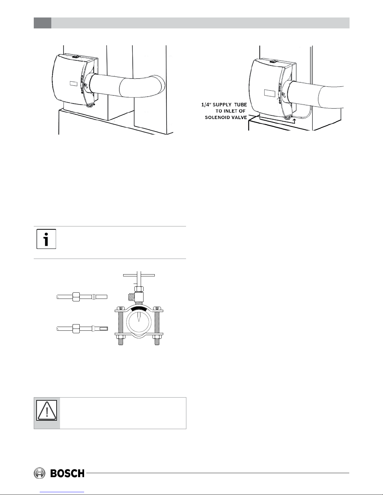
Step 5: Mount the self tapping saddle valve or code
valve on either a cold or a hot water pipe. A side or
top mount is best to avoid clogging from pipe
sediment. Connect 1/4” O.D. tubing to the saddle
valve. Copper tubing requires a brass compression
nut and brass sleeve. Plastic tubing requires a brass
insert inside the tubing, a plastic sleeve on the
outside with a brass compression nut. See Figure 4.
Do not use plastic tubing on hot water or in
contact with any hot plenum surface or duct.
Installation of this saddle valve must meet or
exceed local codes and ordinances.
COPPER
TUBING
PLASTIC
TUBING
Figure #4
Step 6: Connect 1/4” water supply tube to brass
lter at inlet of solenoid. See Figure 5.
Do not use plastic tubing on hot water or in
contact with any hot plenum surface or duct. If
using plastic tubing, use tube support and plastic
compression sleeve.
Figure #5
STEP 7: Replace the evaporator pad with the drain
pan and distributor trough attached. Ensure that the
drain pan is on the bottom and that the spout aligns
with the outlet in the cabinet. The evaporator pad
assembly can only be installed in one direction.
Ensure that the notch at the top in the distributor
trough goes in rst. Do not force the evaporator pad
assembly. If it does not go in easily, it might be
backwards.
STEP 8: Replace the humidier cover, ensuring that
both tabs snap into place.
Step 9: Turn damper knob to the “winter” (open)
position. Turn on water supply and check operation
of humidier. Set humidistat to a demand setting.
(See Humidistat section for installation and
settings) With the air handler off, the solenoid valve
should be closed. Start the air handler, the solenoid
valve should open when the blower motor is
energized. Check ow of water through distributor
trough and evaporator pad. The standard yellow
orice will supply approximately 3.5 GPH of water at
a line water pressure of 60 psi. For low water
pressures (20-40 psi) a larger orange orice (P/N
7738002989) is available to provide the same ow.
Leave humidistat set at the recommended setting.
Connect drain hose to 1/2” spout on humidier
cabinet using hose clamp. Run 1/2” hose to suitable
drain such as oor drain, sewer or laundry sink. Be
sure hose has continuous slope and is not kinked at
any point.
6 720 220 343
Subject to change without prior notice Revised 07-12
Humidity Control Humidistat HUMB-TST-A-A IAQ Series 5
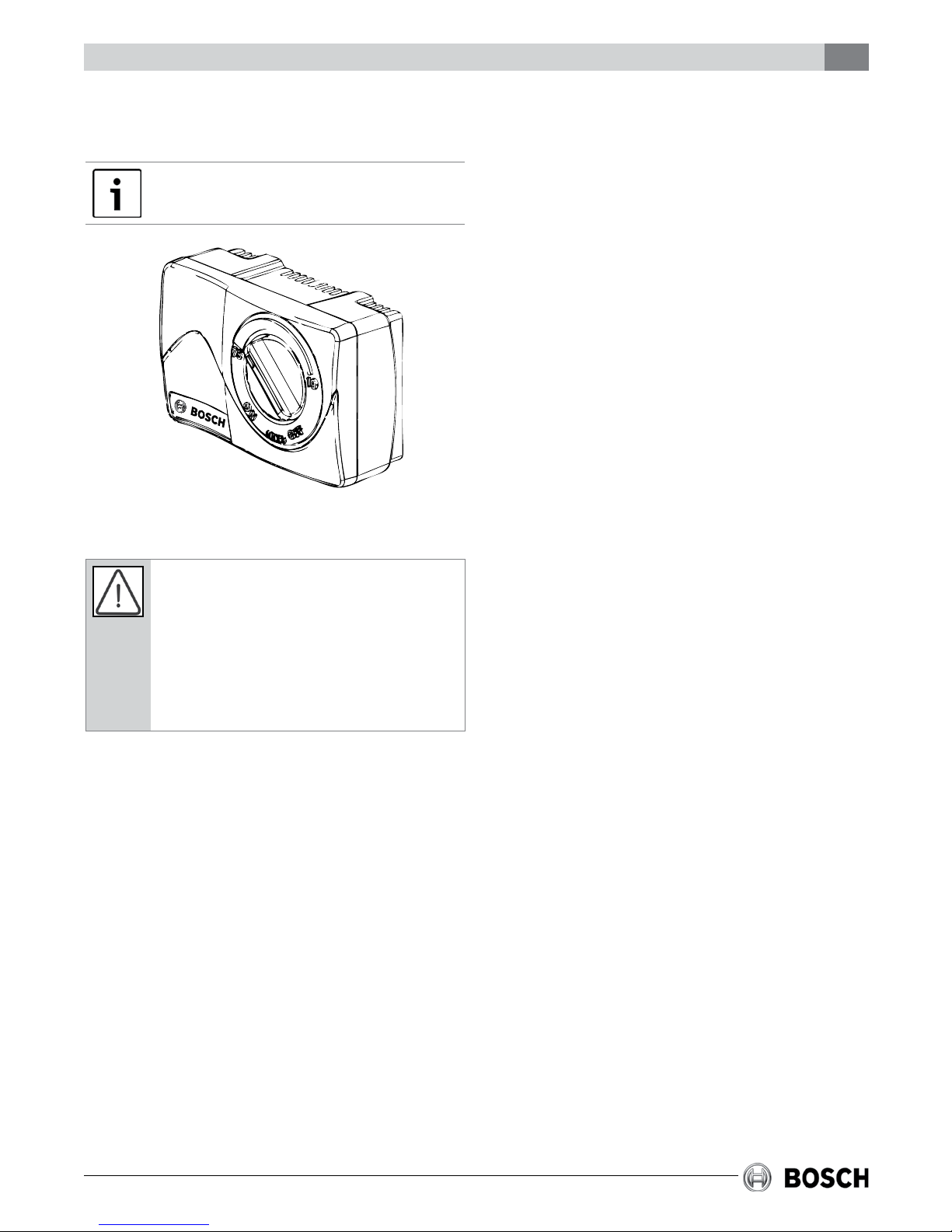
HUMIDITY CONTROL
HUMIDISTAT HUMB-TST—A—A
INSTALLER: Leave owner’s manual with home
owner.
SAFETY
Improper electrical wiring can result in re or
loss
of humidity control. Disconnect electrical
power before installing and servicing. Failure to
disconnect electrical power may result in injury or
death. All local building and electrical codes must
be followed. The humidistat must be installed by
a qualied Technician. Failure to properly install
the humidistat may result in property damage or
personal injury.
Homeowners must read instructions and
understand the operation of the humidistat and the
humidier(s) it controls.
Improper operation can result in over or under
humidication. Over humidication can result in
condensation, structural damage and mold.
Condensation within a building’s structure can
cause loss of structural strength. Condensation can
also enable mold and mildew growth resulting in
personal injury and damage to building structure
and contents.
mounting on the return air duct. Use contacts C
and NO for humidistat operation. Use contacts C
and NC for dehumidistat operation.
RANGE: 10% to 85% RH ELECTRICAL RATING: 30
VAC / 60 VA
OPERATION
Set the control knob to the desired humidity
setting. The recommended setting for optimum
whole-house humidication is 30% to 50%. The
vertical position on the knob is approximately 42%
RH.
Setting the humidistat above or below the
recommended settings may not provide
satisfactory results for your home. Refer to the
Care and Maintenance section of this manual for
recommended settings.
INSTALLATION INSTRUCTIONS—
PRECAUTIONS
The installer must be a qualied technician.
Disconnect electrical power before beginning
installation. Do not install the humidistat on the
warm air duct. Conduct a thorough checkout
before leaving the installation.
WALL MOUNT INSTRUCTIONS—
HUMIDISTAT/DEHUMIDISTAT
VERSIONS
1. Choose a location for the HUMB-TST—H—A
about ve feet above the oor on an inside wall
with average room temperature and relative
humidity conditions.
2. Drill a small hole in the wall and run low voltage
wiring to the location chosen. Pull about 6” of
wire through the hole. Use the entire mounting
gasket (both inside and outside portions) to
seal the wall opening or use foam tape to
prevent drafts from affecting the humidistat
operation. See Figure 6.
APPLICATION
The humidistat provides low voltage control of
humidiers installed in central heating systems.
The humidistat control has a DPST switch and is
designed for wall mounting in the living area, or
Revised 07-12 Subject to change without prior notice
3. Squeeze the top and bottom of the base to
release the face of the humidistat.
4. Mount the base horizontally over the wires.
Attach directly to the wall, using the two screws
provided in the slotted holes.
6 720 220 343
 Loading...