

Bosch HUI31451UC User Manual [en, es, fr]

Bosch ventilation installation manual
Bosch ventilation
DHL 755 B / HUI 31451
DHL 755 B
use and care manual

Safety .......................................................... 1
Installation ...................................................... 2
Before You Begin ....................................................................2
Installation Procedure .................................................................5
Service ......................................................... 6
Before Calling Service .................................................................6
Questions?
1-800-944-2904
www.boschappliances.com
1901MainStreet
5551 McFadden Ave.
Huntington Beach, CA 92649
Irvine,CA92614
We look forward to hearing from you!

Safety
IMPORTANT SAFETYINSTRUCTIONS
READ AND SAVE THESE INSTRUCTIONS
Safety
Important Safety
Instructions
ApplianceHandling Safety •Unit is heavy andrequiresatleast two people or proper equipment to move.
SafetyCodesand Standards •Thisappliance complies with oneormoreofthe following Standards:
Electric Safety •GROUNDING INSTRUCTIONS
•WARNING: If the informationinthis manual is notfollowedexactly,fire or
shock may result causing property damage or personal injury.
•WARNING: Do notrepairorreplace anypartofthe appliance unless specifically recommendedinthe manuals. Improperinstallation, service or maintenance can cause injuryorproperty damage.Refer to this manual for
guidance. All other servicingshouldbedonebyaqualified technician.
•Hidden surfacesmay have sharpedges. Use cautionwhenreachingbehind
or under appliance.
1) UL 858, TheStandardfor the Safety of Household Electric Ranges
2) UL 923, TheStandardfor the Safety of Microwave Cooking Appliances
3) UL 507, TheStandardfor the Safety of Electric Fans
4) ANSI Z21.1-2000, TheAmerican National Standardfor Household Cook-
ingGas Appliances
5) CAN/CSA-C22.2 No.113-M1984 Fans and Ventilators
6) CAN/CSA-C22.2 No.61-M89Household Cooking Ranges
It is the responsibility of the owner and theinstaller to determine if additional
requirementsand/or standardsapply to specific installations.
This appliance must be grounded. In the event of an electricalshort circuit,
grounding reducesthe risk of electric shockbyproviding an escape wire for
the electric current. This appliance is equipped with acordhavingagrounding
wire with agroundingplug. Theplugmustbeplugged into an outletthat is
properly installed andgrounded.
•WARNING: Impropergroundingcan result in ariskofelectricshock.
•Consult aqualifiedelectricianifthe grounding instructions arenot completely
understood,orifdoubt existsastowhetherthe appliance is properly
grounded.
•Donot use an extension cord. If the powersupplycordistoo short, have a
qualified electrician installanoutletnear theappliance.
•For appliancesequipped with acordand plug,donot cutorremove the
ground prong. It must be pluggedinto amatchinggrounding type receptacle
to avoidelectrical shock.Ifthere is anydoubt as to whether thewallreceptacleisproperly grounded, the customershouldhave it checkedbyaqualified
electrician.
•Ifrequiredbythe National Electrical Code (orCanadian ElectricalCode),this
appliance must be installed on aseparatebranchcircuit.
•WARNING:Toreducethe risk of fire or electric shock, do notuse this fanwith
anysolid-statespeed control device.
•Installer-show theowner thelocation of thecircuit breakerorfuse. Mark it for
easy reference.
English1

Safety
•Beforeinstalling, turn power OFF at theservice panel. Lock service panelto
preventpower from being turned ON accidentally.
•WARNING-TOREDUCE THE RISK OF FIRE, ELECTRICSHOCK, OR
INJURYTOPERSONS, OBSERVE THE FOLLOWING:
a) Use this unit only in the manner intendedbythe manufacturer.Ifyou have
questions, contact themanufacturer.
b) Beforeservicing or cleaning unit, switch power offatservice paneland
lock theservice disconnectingmeans to preventpower from being
switched on accidentally.Whenthe service disconnectingmeans cannot
be locked,securelyfastenaprominentwarning device, such as atag,to
theservicepanel.
•Besureyourappliance is properlyinstalled and grounded by aqualified technician.Installation, electricalconnections andgrounding must comply with all
applicable codes.
Ventilation Safety •WARNING-TOREDUCE THE RISK OF FIRE, ELECTRICSHOCK, OR
INJURYTOPERSONS, OBSERVE THE FOLLOWING:
a) Installationworkand electrical wiringmust be done by qualified person(s)
in accordance withall applicable codesand standards,including firerated construction.
b) Sufficient air is neededfor proper combustion andexhausting of gases
throughthe flue (chimney) of fuel burningequipment to preventback
drafting.Follow theheating equipment manufacturer's guideline and
safety standards suchasthose published by the National FireProtection
Association (NFPA), and the AmericanSociety for Heating, Refrigeration
andAir Conditioning Engineers (ASHRAE),and the localcodeauthorities.
c) When cutting or drilling into wall or ceiling, do not damage electrical wiring
and other hidden utilities.
d) Ducted fans must always be vented to the outdoors.
RelatedEquipment Safety •Remove all tape andpackagingbefore usingthe appliance. Destroy thepack-
aging afterunpackingthe appliance. Neverallowchildren to play with packaging material.
•Never modifyoralter theconstructionofthe appliance.For example, do not
removeleveling legs, panels, wire covers or anti-tip brackets/screws.
•CAUTION: Forgeneralventilating use only.Donot usetoexhaust hazardous
or explosive materials andvapors.
•WARNING:Toreducethe risk of fire,use only metal ductwork.
Installation
Before YouBegin
Tools and Parts
Needed
1. Custom Ventilation Hood and Chimney Assembly
2. Ductworkasnecessary (style varies)
3. Duct Ta pe
4. PhillipsHeadScrewdriver
PartsIncluded 1. Filters(2)
2. Halogen bulbs (2, installed)
3. Screws, Flat Phillips3.5 x15cm(4)
Note:You may useFlat Phillips6x5/8 in. screwsasasubstitute.
English2
Installation
4. OneWay Damper
If partsare missing or damaged, call thenumberorwrite to the address listed
inside thefrontcover.
General Information Theventilation unit is designed forinstallation insideacustom-built hoodand
chimney assembly.Itisfor ducting to the outside;Itcannotbeusedinconjunction
with arecirculation unit.
Installationheight above cooktop is theuser’spreference.The lowerthe hood
above the cooktop,the more efficient thecapturing of cooking odors, grease,and
smoke.Thishoodhas beenapproved for installationsaslow as 30” (760 mm)and
as highas36” (900 mm) above thecooktop.The lowerheightmay be inconvenientfor tall people and largecooking vessels.
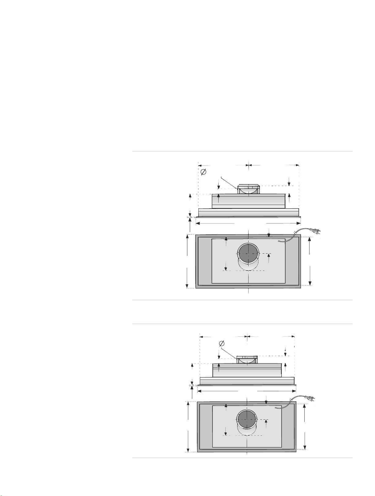
Overall Dimensions
63/8”
(160 mm)
3/8” (9 mm)
(380 mm)
15”
93/4”
(248mm)
6“ (150 mm)
13/8” (35 mm)
20 7/8” (530 mm)
87/8”
(225 mm)
93/4”
(248mm)
21/8” (55 mm)
4“
(100 mm)
13 5/8”
(346 mm)
Figure 5: Overall Dimensions -207/8” (53 cm) models
13 3/4”
(348 mm)
6” (150 mm)
13 3/4”
(348 mm)
63/8” (160 mm)
3/8”
(9 mm)
15”
(380 mm)
13/8” (35 mm)
28 3/4”
(730 mm)
87/8”
(225 mm)
21/8” (55 mm)
4”
(100 mm)
13 5/8”
(346 mm)
Figure 6: Overall Dimensions -283/4” (73 cm) models
English3
Installation
5
Preparation
ElectricalRequirements Theunitrequiresa120V AC, 60Hz. 15Abranch circuit. For futureservice, install
the outlet in an easily accessiblelocation.
Mounting Requirements Theunitmustbemounted to thesurrounding housing. See“GeneralInformation”
on page 3for suggestionsfor determininghoodheight.
For bestresults,install the unit as far up in thehousing or hood as possible. This
will improve the function of theappliance.
When calculating theload forthe housingsupportsystem, be sure to include the
weight of the ventilation unit.See “Ventilation UnitWeight” on page 4. forunit
weight by model.
Table 1: Ventilation Unit Weight
Size Min. Weight
21” (53 cm) 18 1/4 lbs. (8.3 kg)
29” (73 cm) 19 lbs. (8.7 kg)
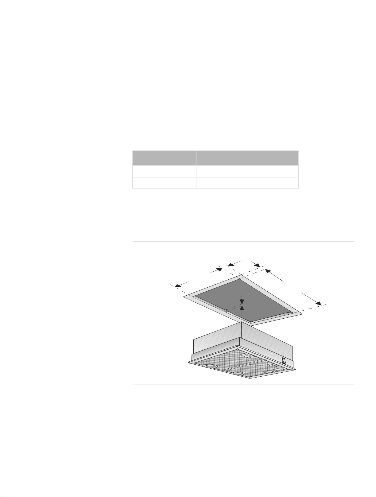
Forproperperformance, thehousing must coverthe entirecookingsurface.
Build housingtocorrespond with Figure 7: Housing Cutout Dimensions-20 7/8”
(53cm) models or Figure 8: HousingCutoutDimensions -283/4” (73 cm)mod-
els.
/8”
(15
mm)
min.
7/8”
13
mm)
(325.3
5/8” (16 mm)
5/8”
(15
(500.3
mm)
19
min.
5/8”
mm)
English 4
Figure 7: Housing Cutout Dimensions-20 7/8” (53cm) models
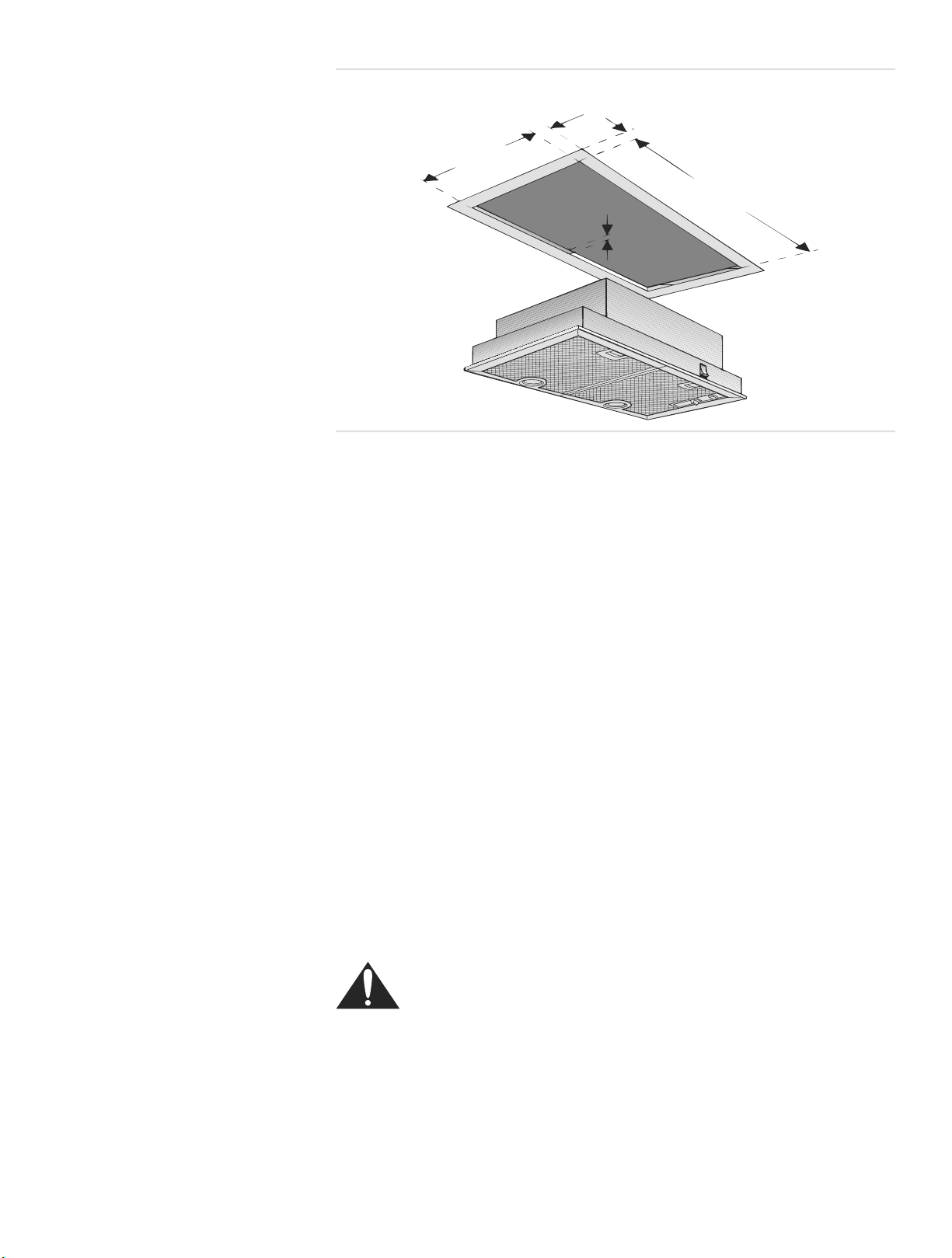
Installation
5/8”
(15
7/8”
13
(325.3
mm)
min.
5/8”
mm)
5/8” (16 mm)
(15
mm)
(700.3
min.
27
5/8”
mm)
Figure 8: Housing Cutout Dimensions-28 3/4” (73cm) models
DuctingRecommendations Theunitisfor ductingtothe outside; it cannot be used in conjunction with arecir-
culation unit.
Forthe most efficient air flow exhaust, use astraight duct runorasfew elbows as
possible.
Do notuse flex ducting.Always usemetal ductworkwith adiameter of 6” (150
mm).
COLDWEATHER installationsshould have an additionalbackdraftdamper
installed to minimizebackward cold air flow and anonmetallic thermalbreak to
minimize conductionofoutside temperaturesaspartofthe ductwork. The damper
shouldbeonthe cold air side of the thermal break.The breakshouldbeasclose
as possible to where the ducting enters the heated portionofthe house.
Always installametal ventcover wherethe ductworkexitsthe house.
Make-Up Air:Local building codes mayrequire theuse of make-up airsystems
when usingductedventilation systemsgreater than specifiedCFM of airmovement. Thespecified CFM variesfromlocale to locale. ConsultyourHVACprofessional forspecific requirementsinyourarea.
Installation Procedure
WARNING: To avoid electrical shock hazard,before installing,
switch power offatthe service paneland lock the paneltoprevent the
power from beingswitchedonaccidentally.
UnpackHood Pull hood from outerpackaging.Removeand discard allpackaging materials.
Remove filter and setaside (See Use andCaremanual for removalinstructions).
Prepare ductwork Install one-waydampersothat theflap opensup(snapsinto place). Note:verify
that the flap opensup(toward the ceiling) before continuing. If necessary,install
thermalbreak andadditional backdraftdamper.
English5
Service
Install Housing See “General Information” on page 3for recommended installationheight and
“Mounting Requirements” on page 4for informationonmounting specifications.
Install housingasdirected by the manufacturer.
Connect to Ductwork Connect ventilation unit to ductwork in house.
Connect Electric Plug electrical cordinto groundedoutlet. Beforeyou pluginanelectrical cord,be
sure allcontrols areinthe OFFposition.
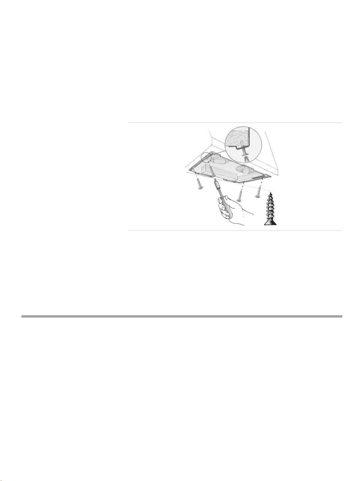
Install the Unit Press unit up into housing until plastic clipsonfront and rear snap into thehous-
ing. Install 4screws through tapholes into housing.
Figure 9: Installthe Unit
FinalSteps Install Filters. See Use andCaremanual for detailedinstructions.
Test TheInstallation Te st the operationofthe blower and thelights.
Note: Be sure to checkfor backdraft. With theblower on high, close the windows
anddoorstothe area to ensure that fan does notcause back drafting in anyoutlet
ventfor anotherappliance.
Service
Before Calling
Service
See Use andCare Manual for troubleshooting information.Refer to theWarranty
in theUse andCareManual.Pleasebepreparedwiththe informationprinted on
your product dataplate when calling.
ProductDataPlate Thedataplate shows themodel andserialnumber.Itislocated under the filter.
English 6

Service
Keepyour invoice or escrow papersfor warranty validationifservice is needed.
DataPlate
behind filter
Figure 10:DataPlate Location
English7
 Loading...