

Bosch GTS1041A Operating/safety Instructions Manual
IMPORTANT: IMPORTANT : IMPORTANTE:
Read Before Using Lire avant usage Leer antes de usar
Operating/Safety Instructions
Consignes de sécurité/d’utilisation
Instrucciones de funcionamiento y seguridad
GTS1041A
Call Toll Free for
Consumer Information
& Service Locations
Pour obtenir des informa-
tions et les adresses de nos
centres de
service après-vente,
appelez ce numéro gratuit
Llame gratis para
obtener información
para el consumidor y
ubicaciones de servicio
1-877-BOSCH99 (1-877-267-2499) www.boschtools.com
For English Version Version française Versión en español
See page 2 Voir page 49 Ver la página 97
1
1600A009XC 09-15.indb 1 9/14/15 1:51 PM

General Safety Rules
READ ALL INSTRUCTIONS. Failure to follow the safety rules listed below and
other basic safety precautions may result in serious personal injury.
Work Area
KEEP CHILDREN AWAY. Do not let visitors con-
tact tool or extension cord. All visitors should be
kept away from work area.
KEEP WORK AREAS CLEAN. Cluttered areas
and benches invite accidents.
MAKE WORKSHOP CHILD-PROOF with padlocks and master switches.
AVOID DANGEROUS ENVIRONMENTS. Don’t
use power tools in damp or wet locations. Keep
work area well lit. Do not expose power tools to
rain. Do not use tool in presence of flammable
liquids or gases.
Personal Safety
KNOW YOUR POWER TOOL. Read the owner’s
manual and labels affixed to the tool. Learn its
application and limitations as well as the specific
potential hazards particular to this tool.
DON’T OVERREACH. Keep proper footing and
balance at all times.
STAY ALERT. Watch what you are doing. Use
common sense. Do not operate tool when you
are tired. Do not operate while under medication
or while using alcohol or other drug.
DRESS PROPERLY. Do not wear loose clothing
or jewelry. They can be caught in moving parts.
Rubber gloves and non-skid footwear are recommended when working outdoors. Wear protective
hair covering to contain long hair.
USE SAFETY GOGGLES. Also face or dust
mask if cutting operation is dusty, and ear plugs
during extended periods of operation.
GUARD AGAINST ELECTRIC SHOCK. Prevent
body contact with grounded surfaces. For example: pipes, radiators, ranges, refrigerator enclosures.
DISCONNECT TOOL FROM POWER SOURCE.
When not in use, before servicing, when changing blades, bits, cutters, etc.
KEEP GUARDS IN PLACE. In working order,
and in proper adjustment and alignment.
REMOVE ADJUSTING KEYS AND WRENCHES. When not in use, before servicing, when
changing blades, bits, cutters, etc.
AVOID ACCIDENTAL STARTING. Make sure the
switch is in the “OFF” position before plugging in
tool.
NEVER STAND ON TOOL OR ITS STAND. Seri-
ous injury could occur if the tool is tipped or if
the cutting tool is accidentally contacted. Do not
store materials on or near the tool such that it
is necessary to stand on the tool or its stand to
reach them.
CHECK FOR DAMAGED PARTS. Before further
use of the tool, a guard or other part that is damaged should be carefully checked to ensure that
it will operate properly and perform its intended
function. Check for alignment of moving parts,
mounting and any other conditions that may affect its operation. A guard or other part that is
damaged should be properly replaced.
All repairs, electrical or mechanical, should
be attempted only by trained repairmen. Con-
tact the nearest Bosch Factory Service Center,
Authorized Service Station or other competent
repair service.
Use only Bosch replacement parts. Others
may create a hazard.
Use only accessories that are recommended
by the manufacturer for your model. Accesso-
ries that may be suitable for one tool, may become hazardous when used on another tool.
Tool Use
DON’T FORCE TOOL. It will do the job better and
safer at the rate for which it was designed.
USE THE RIGHT TOOL. Don’t force small tool
or attachment to do the job of a heavy-duty tool.
Don’t use tool for purpose not intended — for example; don’t use circular saw for cutting tree limbs
or logs.
SECURE WORK. Use clamps or a vise to hold
work. It’s safer than using your hand and it frees
both hands to operate the tool.
USE PROPER DIRECTION OF FEED. Feed
work into a blade or cutter against the direction of
rotation of the blade or cutter only.
NEVER LEAVE TOOL RUNNING UNATTENDED. Turn the power off. Don’t leave tool until it
comes to a complete stop.
Tool Care
DO NOT ALTER OR MISUSE TOOL. These tools
are precision built. Any alteration or modification
not specified is misuse and may result in dangerous conditions.
SAVE THESE INSTRUCTIONS
2
1600A009XC 09-15.indb 2 9/14/15 1:51 PM

General Safety Rules
READ ALL INSTRUCTIONS. Failure to follow the safety rules listed below and
other basic safety precautions may result in serious personal injury.
AVOID GASEOUS AREAS. Do not operate electric tools in gaseous or explosive atmospheres.
Motors in these tools normally spark, and may
result in a dangerous condition.
MAINTAIN TOOLS WITH CARE. Keep tools
sharp and clean for better and safer performance.
Follow instructions for lubricating and changing
accessories. Inspect tool cords periodically and
if damaged, have repaired by authorized service
facility. Inspect extension cords periodically and
replace if damaged. Keep handles dry, clean and
free from oil and grease. Keep saw dust from
building up to the horizontal cast stop wall in the
under table blade cover. See Maintenance section for more information.
Before connecting the tool to a power source
(receptacle, outlet, etc.), be sure voltage supplied is the same as that specified on the
nameplate of the tool. A power source with volt-
age greater than that specified for the tool can
result in serious injury to the user — as well as
damage to the tool. If in doubt, DO NOT PLUG IN
THE TOOL. Using a power source with voltage
less than the nameplate rating is harmful to the
motor.
For your own safety, do not operate your table
saw until it is completely assembled and installed according to the instructions.
ENSURE STABILITY OF SAW. Your table saw
MUST BE BOLTED securely to a stand or workbench. In addition, if there is any tendency for the
table saw to tip over or move during certain operations such as cutting long, heavy boards, use
an auxiliary support.
SELECT A PROPER WORKING LOCATION.
Use the table saw in a well lit area and on a level
surface, clean and smooth enough to reduce the
risk of trips and falls. Use it where neither the operator nor the casual observer is forced to stand
inline with the blade.
Kickback and related warnings
Kickbacks can cause serious injury: A “KICKBACK” occurs when a part of the work piece
binds between the saw blade and the rip fence
or other fixed object. A work piece binding in the
blade due to misalignment, can also cause kickback. During kickback, the work piece can rise
from table and be thrown toward the operator.
Keep your face and body to one side of the saw
blade, and out of line with the saw blade.
KICKBACKS AND POSSIBLE INJURY CAN
USUALLY BE AVOIDED BY:
a. Maintaining the rip fence parallel to the saw
blade.
b. Keeping the saw blade sharp and ensuring
there are no broken teeth. Replacing or sharpening anti-kickback pawls when points become
dull.
c. Keeping saw blade guard, riving knife and anti-
kickback pawls in place and operating properly.
The riving knife must be in alignment with the
saw blade and the pawls must stop a kickback
once it has started. Check their action before
ripping.
d. NOT ripping a work piece that is twisted or
warped or does not have a straight edge to
guide along the rip fence.
e. NOT releasing work until you have pushed it all
the way past the saw blade.
f. Using a Push Stick for ripping widths of 2” to 6”
and an auxiliary fence and Push Block for ripping widths narrower than 2” (See “Basic Saw
Operation, Using The Rip Fence” section, page
34).
g. NOT confining the cut-off piece when ripping or
cross cutting.
h. When ripping, apply the feed force to the sec-
tion of the work piece between the saw blade
and the rip fence. Use Push Stick or Push
Block when appropriate (See item f. above).
i. Feeding material at a rate that does not tax the
saw motor.
j. Using featherboards whenever possible.
k. Immediately stopping the cutting process when
resistance beyond that of normal cutting is encountered.
l. Never cutting without the use of the rip fence or
miter gauge.
SAVE THESE INSTRUCTIONS
3
1600A009XC 09-15.indb 3 9/14/15 1:51 PM

Additional Safety Warnings
READ ALL INSTRUCTIONS. Failure to follow the safety rules listed below and
other basic safety precautions may result in serious personal injury.
PROTECTION:
Eyes, hands, face, ears and body.
TO AVOID BEING PULLED INTO THE SPINNING TOOL, DO NOT WEAR:
• LOOSEFITTINGGLOVES
• LOOSECLOTHING
• NECKTIE,JEWELRY
DO:
• TIEBACKLONGHAIR
• ROLLLONGSLEEVESABOVEELBOWS
a. If any part of your saw is missing, malfunction-
ing, has been damaged or broken, such as the
motor switch, or other operating control, a safety device or the power cord cease operating
immediately until the particular part is properly
repaired or replaced.
b. The injury mitigation system requires contact
with the operator’s body in order to react. This
will cause some injury to be sustained if the
contact occurs. The best defense against injury remains the knowledge of how to safely
operate the saw contained within this manual
and the operator’s attention to the cutting operation underway.
c. Be aware of the status indicator lights. Do not
use the tool unless you understand it is safe to
use.
d. Wear safety goggles and a face shield if op-
eration is dusty. Wear ear plugs or muffs during extended periods of operation. Small loose
pieces of wood or other objects that contact
the rear of the rotating blade can be thrown
back at the operator at excessive speed. This
can usually be avoided by keeping the guard
and riving knife in place for all “THROUGHCUTTING” operations (cutting entirely through
the work) AND by removing all loose pieces
from the table with a long stick of wood IMMEDIATELY after they are cutoff.
e. Use extra caution when the guard assembly is
removed for cutting, dadoing or rabbeting —
replace the guard as soon as that operation is
completed.
f. NEVER turn the saw “ON” before clearing the
table of all tools, wood scraps, etc., except the
SAVE THESE INSTRUCTIONS
work piece and related feed or support devices
for the operation planned.
g. NEVER place your face or body in line with the
cutting tool.
• NEVER place your fingers andhands inthe
path of the saw blade or other cutting tool.
Keep your fingers and hands at least 4 inches
away from the blade or other cutting tool.
• NEVER reachin back of the cutting tool with
either hand to hold down or support the work
piece, remove wood scraps, or for any other
reason. Avoid awkward operations and hand
positions where sudden slip could cause fingers or hand to move into a saw blade or other
cutting tool. Even with the injury mitigation system engaged, these actions can lead to your
hand or arms being forced into the blade at
high speeds. A significant injury is likely under
these conditions.
• DONOTperformanyoperation“FREEHAND”
— always use either the rip fence or the miter
gauge to position and guide the work.
• NEVERusetheripfencewhencrosscuttingor
the miter gauge when ripping. DO NOT use the
rip fence as a length stop.
• NEVERholdontoortouchthe“freeend”ofthe
work piece or a “free piece” that is cut off, while
power is “ON” and/or the saw blade is rotating.
• Shut“OFF”thesawanddisconnectthepower
cord when removing the table insert, changing the cutting tool, removing or replacing the
blade guard, resetting the safety system or
making adjustments.
• Provideadequatesupporttotherearandsides
of the saw table for wider or long work pieces.
• Plasticandcomposition(likehardboard)materials may be cut on your saw. However, since
these are usually quite hard and slippery, the
anti-kickback pawls may not stop a kick back.
Therefore, be especially attentive to following
proper set-up and cutting procedures for ripping. Do not stand, or permit anyone else to
stand, in line with a potential kickback.
h. If you stall or jam the saw blade in the work
piece, turn saw “OFF”, remove the work piece
from the saw blade, and check to see if the saw
4
1600A009XC 09-15.indb 4 9/14/15 1:51 PM
blade is parallel to the table slots or grooves
and if the riving knife is in proper alignment
with the saw blade. If ripping at the time, check
to see if rip fence is parallel with the saw blade.
Readjust as indicated.
i. NEVER gang crosscut — lining up more than
one work piece in front of the blade (stacked
vertically, or horizontally outward on the table)
and then pushing through saw blade. The blade
could pick up one or more pieces and cause a
binding or loss of control and possible injury.
j. DO NOT remove small pieces of cut-off mate-
rial that may become trapped inside the blade
guard while the saw is running. This could endanger your hands or cause a kick back. Turn
saw “OFF” and wait until blade stops.
KNOW YOUR CUTTING TOOLS
Dull, gummy or improperly sharpened or set cutting tools can cause material to stick, jam, stall
the saw, or kickback at the operator. Minimize potential injury by proper cutting tool and machine
maintenance. NEVER ATTEMPT TO FREE A
STALLED SAW BLADE WITHOUT FIRST TURNING THE SAW OFF.
a. NEVER use grinding wheels, abrasive cut-off
wheels, friction wheels (metal slitting blades)
wire wheels or buffing and sanding wheels,
molding cutter, wobble or adjustable dado.
b. USE ONLY RECOMMENDED ACCESSO-
RIES.
c. Crosscutting operations are more conveniently
worked and with greater safety if an auxiliary
wood facing is attached to the miter gauge.
(See Page 32).
d. Make sure the top of the cutting tool rotates to-
ward you when standing in normal operating
position. Also make sure the cutting tool, arbor
collars and arbor nut are installed properly.
Keep the cutting tool as low as possible for the
operation being performed. Keep all guards in
place whenever possible.
• Do not use any blade or other cutting tool
marked for an operating speed less than 4800/
min (RPM). Never use a cutting tool larger in
diameter than the diameter for which the saw
was designed. For greatest safety and efficiency when ripping, use the maximum diameter
blade for which the saw is designed, since under these conditions the riving knife is nearest
the blade.
e. Make sure the table insert is flush or slightly
below the table surface on all sides except for
rear side. NEVER operate the saw unless the
proper insert is installed.
THINK SAFETY
SAFETY IS A COMBINATION OF OPERATOR
COMMON SENSE AND ALERTNESS AT ALL
TIMES WHEN THE TABLE SAW IS BEING
USED.
Do not allow familiarity
(gained from frequent use of
your table saw) to become common place. Always remember that a careless fraction of a second is sufficient to inflict severe injury.
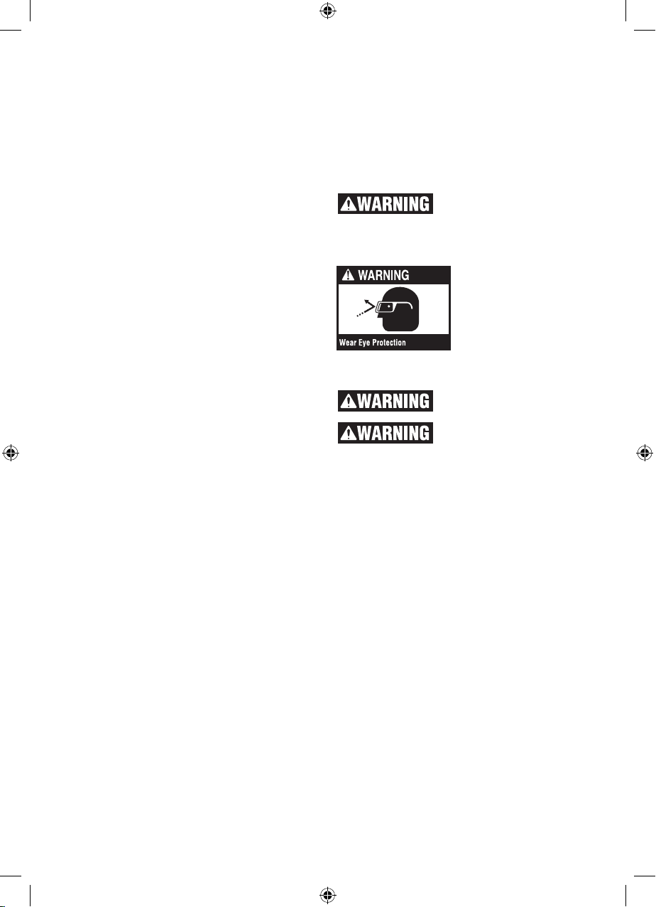
The operation of any power tool can result in foreign
objects being thrown into
the eyes, which can result
in severe eye damage. Always wear safety goggles
that comply with ANSI
Z87.1 (shown on package) before commencing
power tool operation.
Do not use a cellular phone
when operating the table saw.
Some dust created by pow-
er sanding, sawing, grinding, drilling, and other construction activities
contains chemicals known to cause cancer,
birth defects or other reproductive harm.
Some examples of these chemicals are:
• Leadfromlead-basedpaints,
• Crystalline silica from bricks and cement and
other masonry products, and
• Arsenicandchromiumfromchemicallytreated
lumber.
Your risk from these exposures varies, depending
on how often you do this type of work. To reduce
your exposure to these chemicals: work in a well
ventilated area, and work with approved safety
equipment, such as those dust masks that are
specially designed to filter out microscopic particles.
Before each use, review all warnings located
on the table saw.
SAVE THESE INSTRUCTIONS
5
1600A009XC 09-15.indb 5 9/14/15 1:51 PM
Motor Specifications
In the event of a malfunction or breakdown,
grounding provides a path of least resistance
for electric current to reduce the risk of electric
shock. This tool is equipped with an electric cord
having an equipment-grounding conductor and a
grounding plug. The plug must be plugged into
a matching outlet that is properly installed and
grounded in accordance with all local codes and
ordinances. This saw is wired for operation on
110-120 volts, 60 Hz. alternating current. Before
connecting the motor cord to power source, make
certain the switch is in the “OFF” position and be
sure the electric current is of the same characteristics as stamped on the table saw nameplate.
Connection To A Power Source
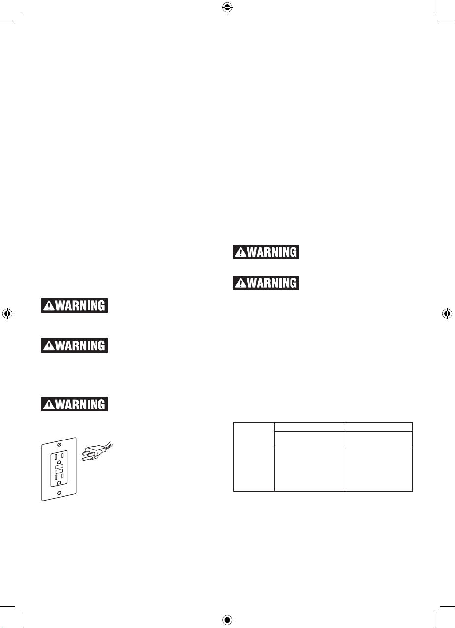
This machine must be grounded while in use to
protect the operator from electric shock.
Plug power cord into a 110-120V properly grounded type outlet protected by a 15-amp dual element time delay fuse or circuit breaker.
Not all outlets are properly grounded. If you are
not sure that your outlet, as pictured on this page,
is properly grounded; have it checked by a qualified electrician.
To avoid electric shock, do not
touch the metal prongs on the
plug when installing or removing the plug to or
from the outlet.
Failure to properly ground this
power tool can cause electrocution or serious shock, particularly when used
near metal plumbing or other metal objects. If
shocked, your reaction could cause your hands
to hit the tool.
If power cord is worn, cut or
damaged in any way, have it
replaced immediately to avoid shock or fire hazard.
Your unit is for use on 120
volts and is equipped with a
3-conductor cord and
grounding type plug, approved by Underwriters
Laboratories and the Canadian Standards Association.
The ground conductor has a
green jacket and is attached to the tool housing at
one end and to the ground prong in the attachment plug at the other end.
If the outlet you are planning to use for this power
tool is of the two-prong type, DO NOT REMOVE
OR ALTER THE GROUNDING PRONG IN ANY
MANNER. Have a qualified electrician replace
the TWO-prong outlet with a properly grounded
THREE-prong outlet. Do not use any adapter
plugs.
Improper connection of the equipment-grounding
conductor can result in a risk of electric shock.
The conductor with insulation having an outer
surface that is green with or without yellow stripes
is the equipment grounding conductor. If repair or
replacement of the electric cord or plug is necessary, do not connect the equipment grounding
conductor to a live terminal.
Check with a qualified electrician or service personnel if the grounding instructions are not completely understood, or if in doubt as to whether
the tool is properly grounded.
Extension Cords
Replace damaged cords im-
cords can shock, burn or electrocute.
extension cords which have 3-prong grounding type plugs and 3-pole receptacles which
accept the tool’s plug. If an extension cord is
necessary, a cord with adequate size conductors
should be used to prevent excessive voltage
drop, loss of power or overheating. The table
shows the correct size to use, depending on cord
length and nameplate amperage rating of tool. If
in doubt, use the next heavier gauge. Always use
U.L. and CSA listed extension cords.
RECOMMENDED SIZES OF EXTENSION
CORDS 120 VOLT ALTERNATING CURRENT
TOOLS
Tool’s
Ampere
Rating
3-6 18 16 16 14 0.75 0.75 1.5 2.5
6-8 18 16 14 12 0.75 1.0 2.5 4.0
8-10 18 16 14 12 0.75 1.0 2.5 4.0
10-12 16 16 14 12 1.0 2.5 4.0 —
12-16 14 12 — — — — — —
NOTE: The smaller the gauge number, the heavier the cord.
mediately. Use of damaged
Always use proper extension cord. Use only 3-wire
Cord Size in A.W.G. Wire Sizes in mm
Cord length in feet Cord length in Meters
25 50 100 150 15 30 60 120
2
SAVE THESE INSTRUCTIONS
6
1600A009XC 09-15.indb 6 9/14/15 1:51 PM

Table of Contents
General Safety Rules....................................2
Additional Safety Warnings ........................... 4
Glossary of Terms ......................................... 7
Tools Needed for Assembly .......................... 8
Getting to Know Your Table Saw ................... 9
Unpacking And Checking Contents .............. 12
Assembly ...................................................... 13
Glossary of Terms
ANTI-KICKBACK PAWLS
Spring-loaded “fingers” that engage the work
piece as it is being fed through the saw. They
restrict movement of the work piece back in the
direction of the operator.
ARBOR
The shaft on which a cutting tool is mounted.
ACTIVE RESPONSE TECHNOLOGY™ INJURY
MITIGATION SYSTEM
The system capable of detecting contact between a human and the saw’s blade, which then
pushes the blade under the table preventing a
more severe injury.
BARRIER GUARD
An assembly that consists of the mounting fork
and two side barriers. This assembly is intended
to provide a physical barrier between the operator and the spinning saw blade.
BEVEL
Blade angle relative to the table surface.
BOSCH TOOLBOX APP
Smart phone application used in conjunction with
NFC to interact with the Active Response Technology™ System
BYPASS SWITCH
The control that allows the saw user to disable
the Active Response Technology™ injury mitigation system for a single cycle of the power switch.
CROSSCUT
A cutting or shaping operation made across the
width of the work piece cutting the work piece to
length.
DADO
A non-through cut which produces a square sided notch or trough in the work piece.
Setting / Resetting the Active Response
Technology™ system .................................... 13
Adjustments .................................................. 19
Basic Table Saw Operation ........................... 25
Maintaining your Table Saw .......................... 41
Accessories .................................................. 43
Troubleshooting ............................................ 44
ELECTRICALLY CONDUCTIVE MATERIALS
Materials that permit the flow of electrical current.
Metals such as steel, aluminum, and copper are
examples of electrically conductive materials.
FEATHERBOARD
A device which can help guide work pieces during rip type operation by keeping work piece in
contact with the rip fence. It also helps prevent
kickback.
FREEHAND
Performing a cut without a fence, miter gauge, fixture, hold down or other proper device to keep the
work piece from twisting during the cut and can
be a safety hazard.
GUM
A sticky, sap-based residue from wood products.
After it has hardened, it is referred to as “RESIN”.
HEEL
Misalignment of the blade which causes the trailing or out feed side of the blade to contact the
cut surface of the work piece. Heel can cause
kickback, binding, excessive force, burning of the
work piece or splintering. In general, heel creates
a poor quality cut and can be a safety hazard.
KERF
The space in the work piece where the material
was removed by the blade.
KICKBACK
An uncontrolled grabbing and throwing of the
work piece back toward the front of the saw during a rip type operation.
LEADING END
The end of the work piece which, during a rip
type operation, is pushed into the cutting tool first.
7
1600A009XC 09-15.indb 7 9/14/15 1:51 PM
MOLDING
A non-through cut which produces a special
shape in the work piece used for joining or decoration.
NEAR FIELD COMMUNICATIONS (NFC)
A wireless technology for communicating between enabled devices such as smart phone.
This tool is NFC enabled.
NON THROUGH-CUTTING
Any cutting operation where the blade does not
extend through the work piece (e.g. Dado, Rabbet).
PUSH BLOCK
A device used for ripping-type operations too
narrow to allow use of a Push Stick. Use a Push
Block for rip widths less than 2 inches.
PUSH STICK
A device used to feed the work piece through the
saw during narrow ripping-type operation and
helps keep the operator’s hands well away from
the blade. Use the Push Stick for rip widths less
than 6 inches and more than 2 inches.
RABBET
A notch in the edge of a work piece. Also called
an edge dado.
REVOLUTIONS PER MINUTE (R.P.M.)
The number of turns completed by a spinning object in one minute.
RIPPING
A cutting operation along the length of the work
piece cutting the work piece to width.
RIVING KNIFE OR SPREADER
A device that keeps the kerf of the work piece
open as the material is cut. This minimizes the
potential of the work piece binding against the
saw blade.
SMART GUARD
A system made up of 3 components: Riving Knife
or Spreader, Anti-Kickback Pawls, and Main Barrier Guard.
THROUGH-CUTTING
Any cutting operation where the blade extends
through the workpiece.
WORK PIECE
The item on which the cutting operation is being performed. The surfaces of a work piece are
commonly referred to as faces, ends and edges.
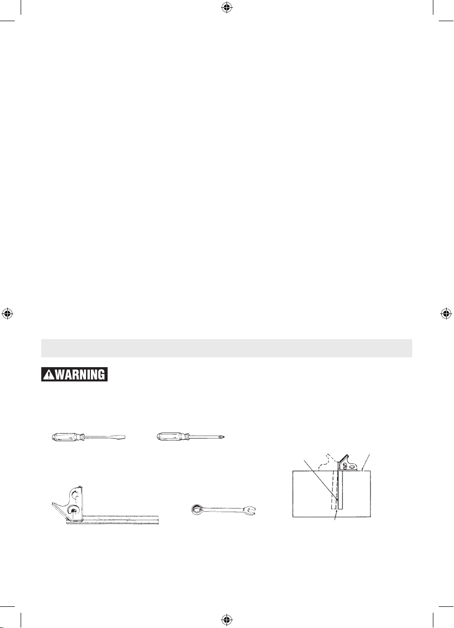
Tools Needed for Assembly
Disconnect plug from power source before performing any assembly,
adjustment or repair to avoid possible injury.
COMBINATION SQUARE MUST BE TRUE
FLAT SCREWDRIVER
COMBINATION SQUARE
1600A009XC 09-15.indb 8 9/14/15 1:51 PM
PHILLIPS SCREWDRIVER
10 MM WRENCH
OR ADJUSTABLE WRENCH
DRAW LIGHT LINE ON
BOARD ALONG THIS EDGE.
SHOULD BE NO GAP OR OVERLAP
HERE WHEN SQUARE IS FLIPPED
OVER IN DOTTED POSITION.
8
STRAIGHT EDGE OF BOARD
3/4” THICK. THIS EDGE
MUST BE PERFECTLY
STRAIGHT.
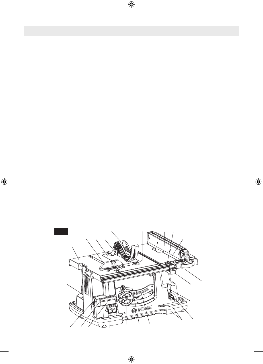
Getting To Know your Table Saw
1. POWER SWITCH
Switch for turning motor on and off. Switch incorporates a hole for use with padlock to prevent
accidental starting.
2. TABLE
Provides large working surface to support work
piece.
3. BASE / SUB-BASE
Supports table saw. Sub-base provides additional
stability and ability for easy sliding onto surfaces.
Holes are provided in base to bolt the saw to a
workbench or stand.
4. BLADE BEVEL LOCK HANDLE
Locks the blade to desired bevel angle.
5. TABLE EXTENSION
Provides a larger work surface for wider work
pieces.
6. TABLE EXTENSION LOCK HANDLE
Allows you to lock the table extension at desired
distances.
7. ELEVATION WHEEL
Elevates or lowers the blade. Also used to tilt the
blade 0 to 45 degrees.
8. BLADE BEVEL SCALE
Shows the degree the blade is tilted.
9. RIP FENCE SCALE
Shows the distance from the blade to rip fence
through a convenient viewing and magnifying
window. Lower portion of scale can be used up to
12.75 inches. Upper portion of scale is used for
cuts beyond 12.75 inches.
10. MITER GAUGE
Head can be locked in desired position for crosscutting or mitering by tightening the lock knob.
ALWAYS SECURELY LOCK IT WHEN IN USE.
11. RIP FENCE STORAGE
Conveniently stores rip fence on bottom of table
when not in use.
12. PRE-CUT (KERF) INDICATOR
Allows you to mark and locate exactly where the
blade will enter the work piece.
13. MITER GAUGE STORAGE
Conveniently stores miter gauge when not in use.
14. BLADE STORAGE & WRENCH
Allows you to store 10” blades, blade wrench
and activation cartridge installation tool. Blade
wrench also has a 10mm hex hole allowing assembly of the Gravity-Rise stand and for use with
dado clamp bolt.
15. HEX WRENCH / PHILLIPS SCREWDRIVER
Hex wrench for adjusting various hex head bolts
on saw. Phillips screwdriver is for assembling the
saw to a Gravity-Rise stand.
16. CORD WRAP
Allows you to easily secure the cord so it’s out of
the way when transporting or storing.
17. VACUUM HOOK-UP
Your table saw is equipped for vacuum hook-up.
This feature will allow you to attach any 2-1/4”
vacuum hose into the dust port provided for convenient saw-dust removal. An adaptor is available
for use with alternate hose sizes.
Fig. 1
13
10 21 35
2
26 27 25
19 12
4 8
7
1
18
9
5
11
6
24
3
23
9
1600A009XC 09-15.indb 9 9/14/15 1:51 PM
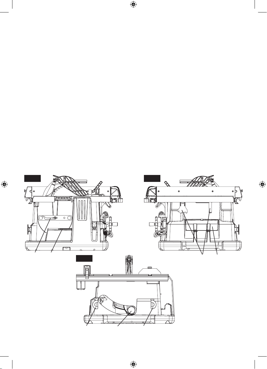
18. RIP FENCE
Exclusive Self-Aligning, Squarelock rip fence can
be easily moved or locked in place by simply raising or lowering lock handle.
19. SMART GUARD SYSTEM
Consists of three key elements: Adjustable (3
position) Riving Knife, Anti-Kickback Pawls, and
Barrier Guard Device. All of these are part of a
modular system that requires no tools to assemble or disassemble. This Guard System must
always be in place and working properly for all
through-cutting cuts.
20. SMART GUARD SYSTEM STORAGE
When not in use or for transportation, the Main
Barrier Guard and Anti-Kickback Pawls can be
stored under the right side table extension.
21. TABLE INSERT
Removable for removing or installing blade or
other cutting tools, to adjust or store the riving
knife, and to reset the Active Response Technol-
22. TABLE INSERT LOCK
Rotates to retain or eject the table insert in the
table.
23. PUSH STICK
Allows you to rip smaller pieces of stock with a
greater level of safety.
24. PUSH STICK STORAGE
On tool storage location for the push stick.
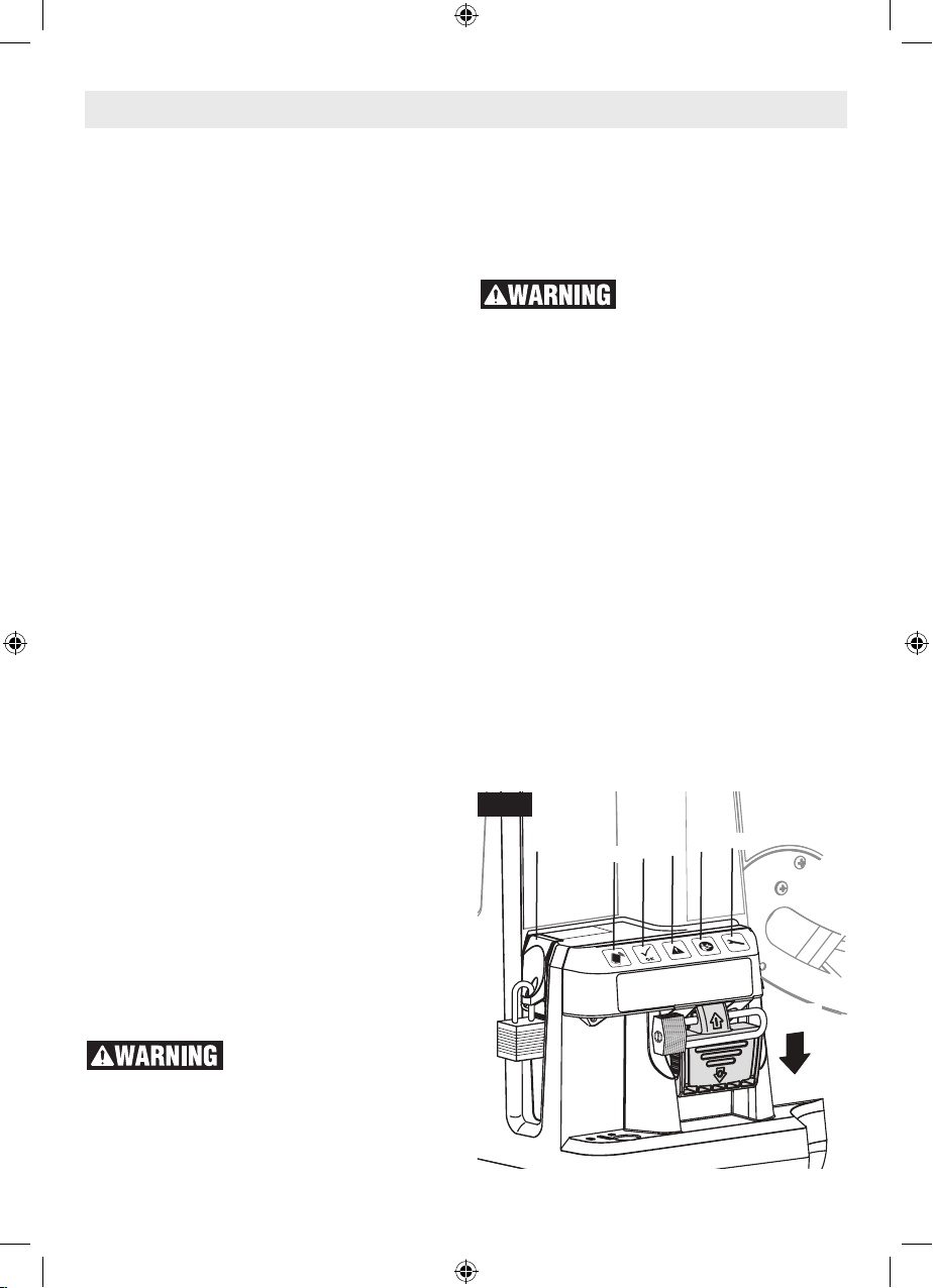
25. INFORMATION PANEL
The system of indicator LEDs and the NFC feature that inform the operator about the tool’s current status
26. BYPASS SWITCH
The control that allows the saw user to disable
the Active Response Technology™ injury mitigation system for a single cycle of the power switch.
A hole is provided to padlock this switch so that
only authorized users can disable the Active Response Technology™ system.
ogy™ injury mitigation system.
Fig. 2a Fig. 2b
14 15
Fig. 2c
3420
17 1616
10
1600A009XC 09-15.indb 10 9/14/15 1:51 PM
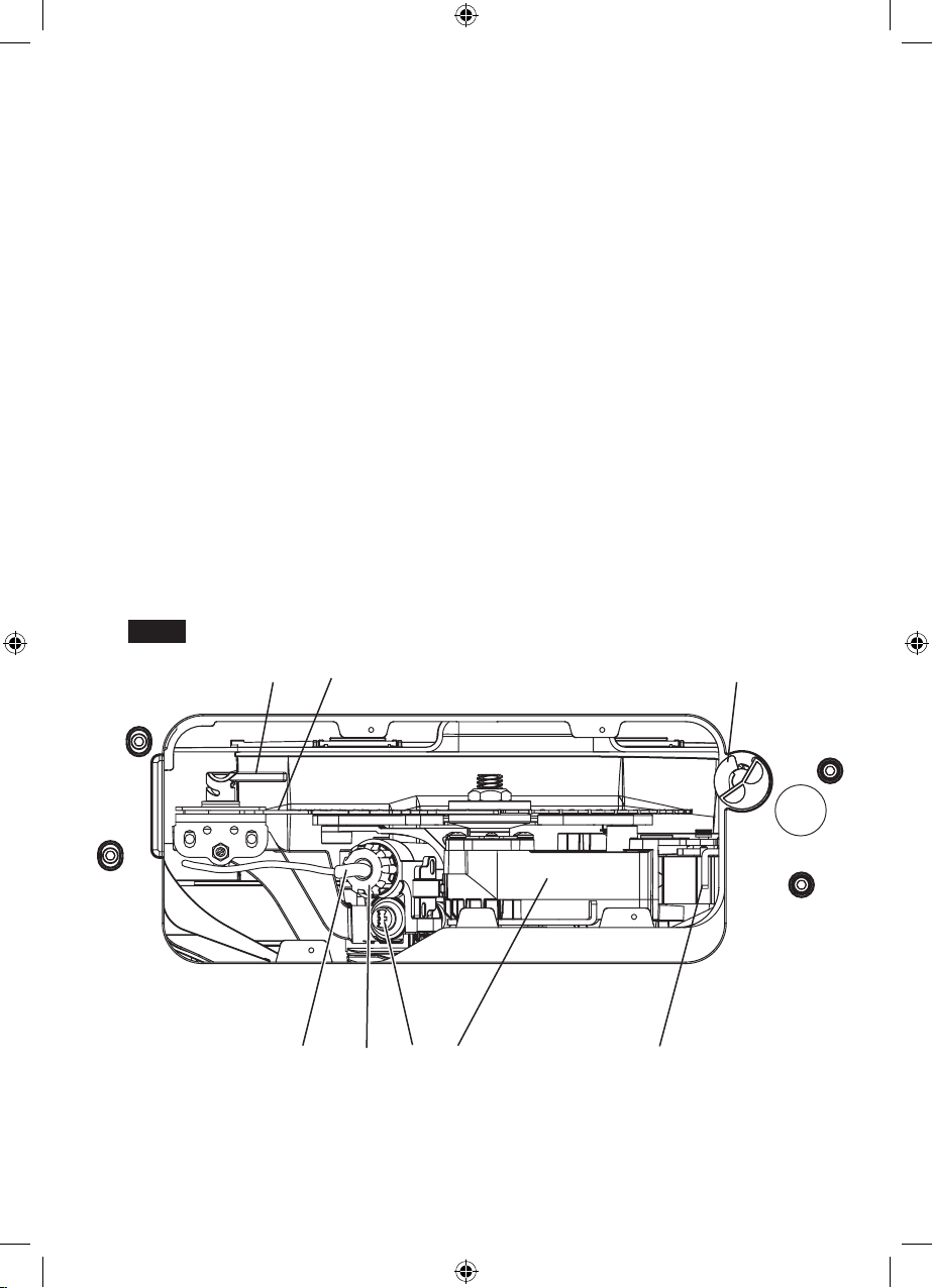
27. NEAR FIELD COMMUNICATION
INTERFACE
Target to place a smart phone with the Bosch
power tools app next to this surface to get a status report about the saw
28. DROP ARM
Moves the blade down and away from the operator after contact between the user and the blade
is detected.
29. ACTIVATION CARTRIDGE
Contains two single shot cylinders each of which
can independently force drop arm to drop below
table surface away from the user. Only one of the
two single shot cylinders is active during operation.
30. LATCH
Ensures the drop arm is held in the proper position for operation. The latch also prevents the
arm returning to the closed position until a new
Activation Cartridge is properly installed
31. DROP ARM LOCK
Ensures the drop arm stays underneath the table
after activation. Release for reset to operating
position.
Fig. 2d
32. DETECTION PLATE
Allows the Active Response Technology™ to
measure the blade for signs of user contact with
the saw blade.
33. ACTIVATION CARTRIDGE RETAINER
Holds the Activation Cartridge in place during
operation and activation. It must be installed
properly to latch the drop arm in the operating
position.
34. SIDE STORAGE COMPARTMENT
Holds spare activation cartridges, quick reset instructions, and the manual.
35. RIVING KNIFE OR SPREADER
A device that keeps the kerf of the work piece
open as the material is cut. This minimizes the
potential of the work piece binding against the
saw blade. It is stored under table when not in
use.
36. CARTRIDGE PLUG
Electrical connection that links the saw electronics to the activation cartridge.
37. RIVING KNIFE RELEASE LEVER
Lever that allows for adjustments
35
2237
29 28 313336
11
1600A009XC 09-15.indb 11 9/14/15 1:51 PM
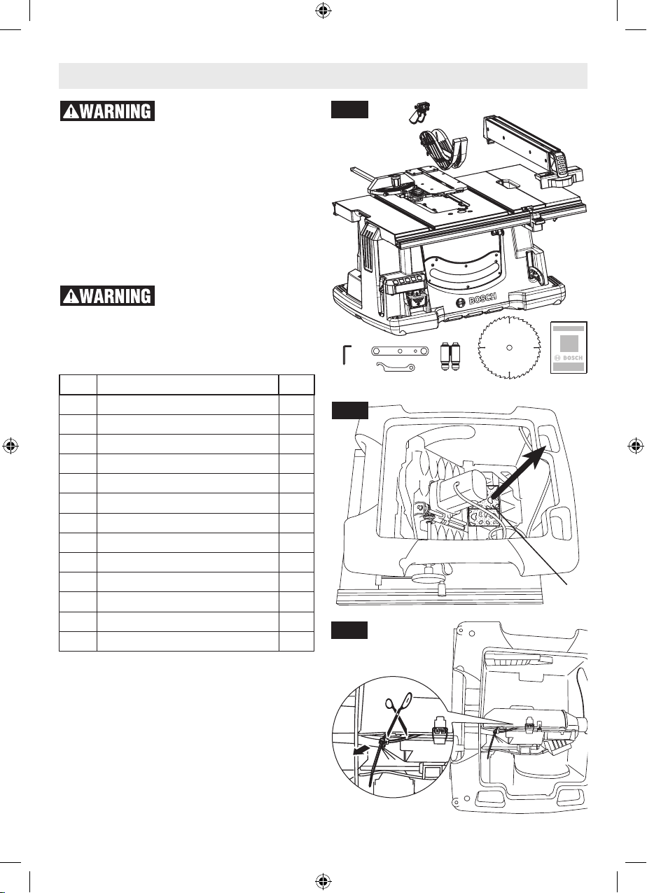
Unpacking And Checking Contents
To avoid injury from unexpected starting or electrical
shock during unpacking and setting up, do not
plug the power cord into a source of power.
This cord must remain unplugged whenever you
are working on the table saw.
Model GTS1041A Table Saw is shipped complete
in one carton.
Separate all parts from packing materials and
check each one with the illustration and the list
of loose parts to make certain all items are accounted for before discarding any packing material
(Fig. 3a).
If any parts are missing, do
not attempt to assemble the
table saw, plug in the power cord or turn the
switch on until the missing parts are obtained
and are installed correctly.
TABLE OF LOOSE PARTS (Fig. 3a)
ITEM DESCRIPTION QTY.
1 Table Saw 1
2 Rip Fence 1
3 Table Insert 1
4 Barrier Guard Assembly 1
5 Anti-Kickback Pawls 1
6 Miter Gauge 1
7 Push Stick 1
8 Activation Cartridge 1
9 Blade, 10”, 40 Tooth 1
10 Blade Wrench 1
11 Activation Cartridge Installation Tool 1
12 Hex Wrench / Philips Screwdriver 1
13 Manual 1
• Remove Styrofoam block A (for shipping pur-
pose only) located between the table and motor
(Fig. 3b). Styrofoam block B (not shown) is located
between the drop arm and throat plate. It needs to
be removed to enable the tool for it’s first use. You
may cause damage to the table saw’s mechanical
systems if the Styrofoam is not removed.
• Cut thecable tie thatholds the drop arm during transportation using scissors or wire cutters as
shown (Fig. 3c). Then pull the cable tie out and
discard.
Fig. 3a
12
Fig. 3b
Fig. 3c
5
4
6
10
3
1
11
8
9
2
7
13
A
12
1600A009XC 09-15.indb 12 9/14/15 1:51 PM
Assembly
SETTING / RESETTING THE ACTIVE
RESPONSE TECHNOLOGY™ INJURY
MITIGATION SYSTEM
To prevent personal injury,
always disconnect the plug
from the power source before making any adjustments.
The Active Response Technology™ system prevents the motor from restarting if the switch is on
when the plug is connected to a power source.
Automatic restart protection helps prevent accidental startups after power has been interrupted,
e.g. the tool was unplugged with the power switch
locked in the ON position. To resume operation,
turn power switch to the OFF position, then restart the tool.
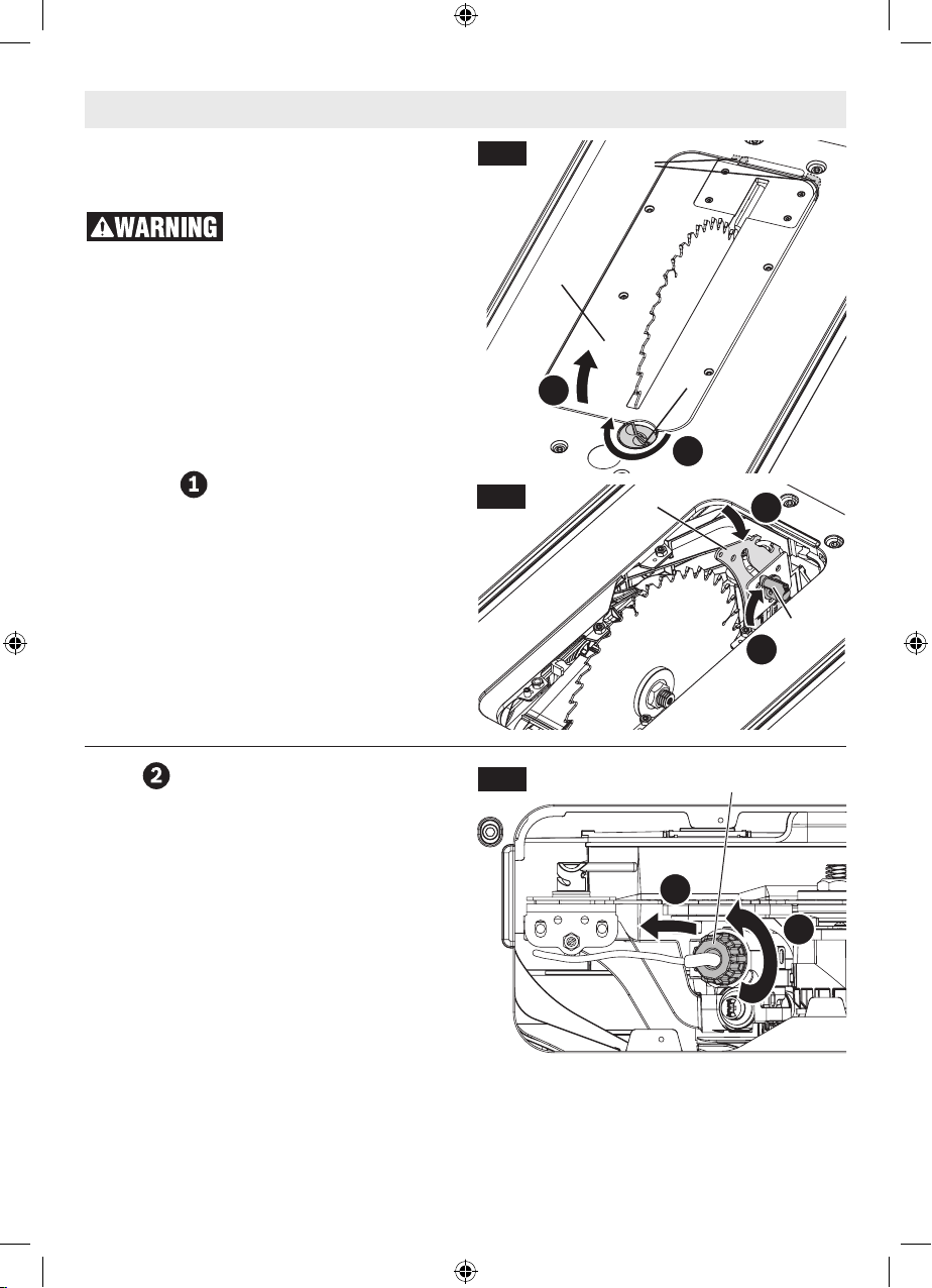
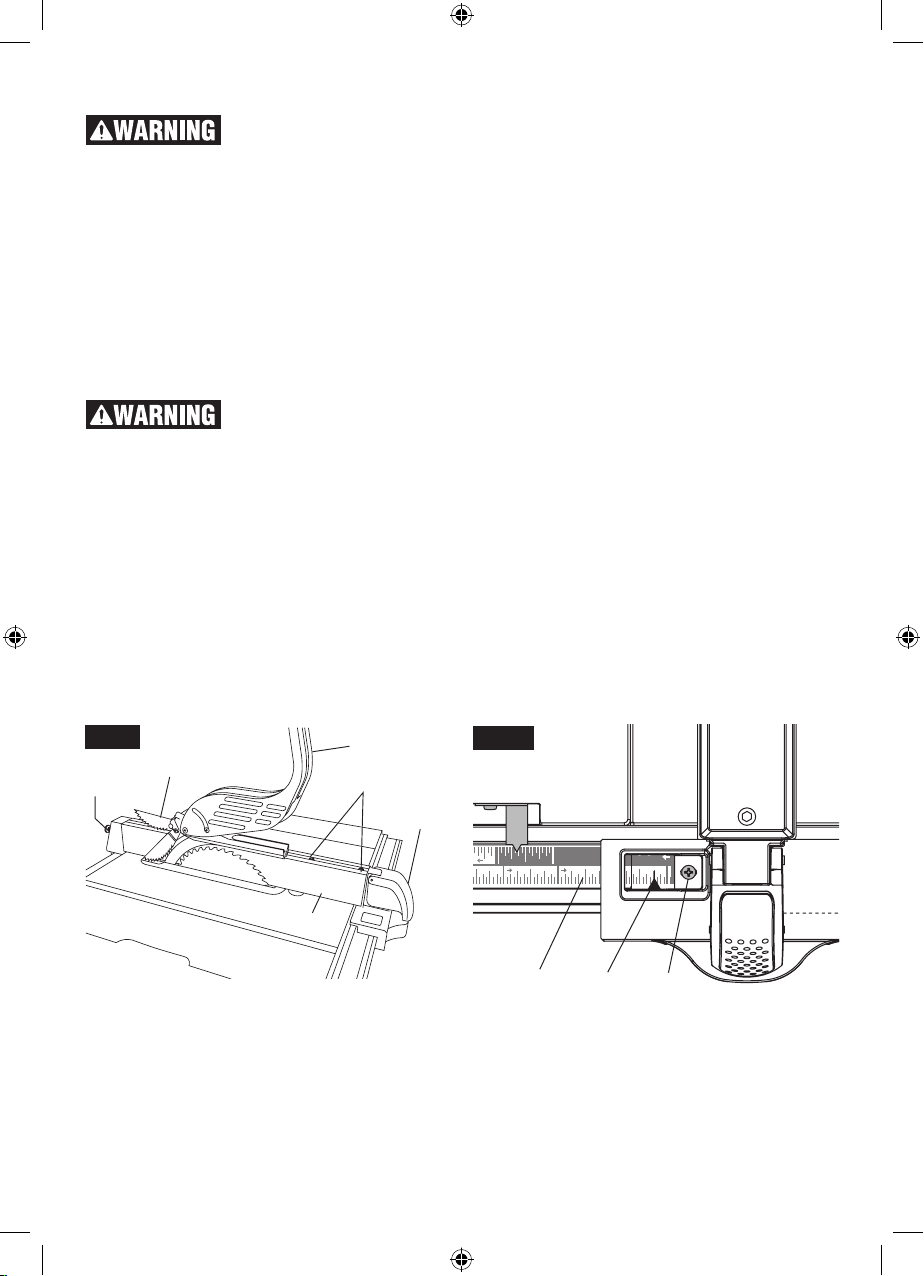
DISASSEMBLE
1. Turn elevation wheel clockwise until the blade
is up as high as it will go, remove any parts of
the Smart Guard system that were in use, then
remove table insert 21 by rotating the table insert lock 22, and use the front edge (Fig. 4) to
lift clear off the table.
2. Ensure the riving knife 35 is set below the top
position. Lower the riving knife by loosening the
riving knife release lever 37 (Fig. 5). For more
information see “POSITIONING THE RIVING
KNIFE” section on page 15.
Fig. 4
Fig. 5
21A
21
B
22
A
35
D
37
C
REPLACE CARTRIDGE
3. Using the activation cartridge installation tool
loosen the activation cartridge retainer 33
counterclockwise then continue to unscrew the
activation cartridge retainer by hand until it is
free on the wire. Slide along the wire to the rear
of the saw near the riving knife (Fig. 6).
Fig. 6
33
F
E
13
1600A009XC 09-15.indb 13 9/14/15 1:51 PM
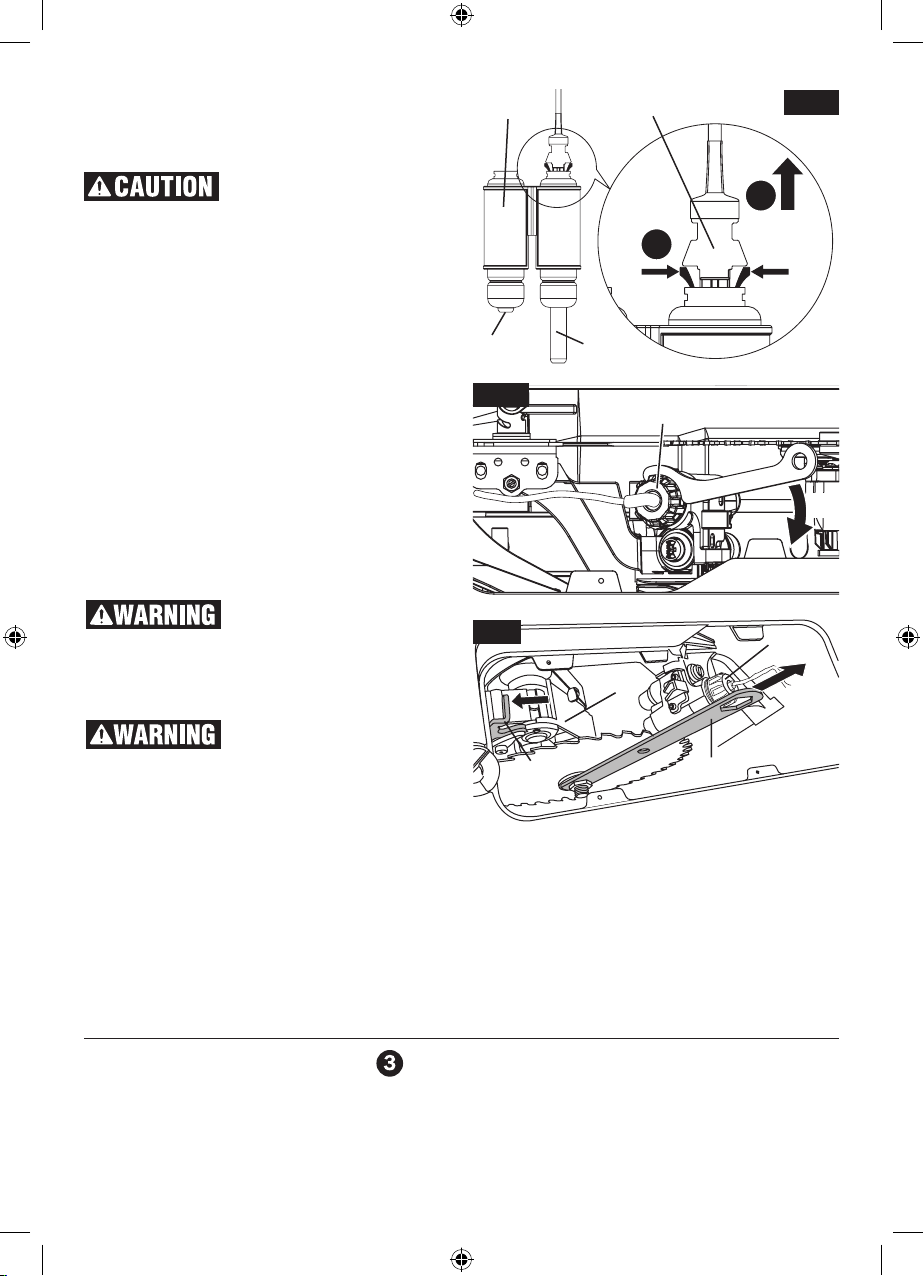
4. If an Activation Cartridge 28 is present, discon-
nect the cartridge plug 36 from the cartridge by
squeezing the latches between the thumb and
forefinger, then sliding the plug back (Fig. 7).
Extreme force on this wire
may damage it. The Active
Response Technology™ system will disable the
saw if the wire is damaged.
5. Grasp the left cylinder of Activation Cartridge
(if present) and slide it up out of the saw. If
the system has just fired the active cylinder,
then the right side piston 28b will extend over
an inch out of the cartridge (Fig. 7). When both
pistons are extended, discard the cartridge.
6. Slide a functioning Activation Cartridge 28a into
the right position.
7. Reattach the cartridge plug 36 to the cartridge’s
right side cylinder.
8. Push down on the left cylinder Activation Car-
tridge 28 with one hand. Tighten the Activation
Cartridge Retainer 33 clockwise with the other
hand into the saw until it is finger tight. Then
using the activation cartridge installation tool
rotate tighten the retainer into place 1/8th turn
further (Fig. 8).
Always tighten the activa-
tion cartridge retainer as
instructed. Failure to tighten the activation car-
tridge retainer as instructed can reduce effectiveness of the Active Response Technology™ system and result in tool damage and personal injury.
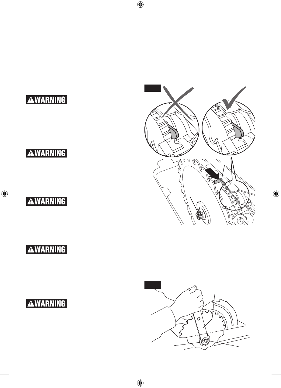
Ensure the riving knife is
positioned away from the
path of the hand as it moves upward. Injury to
the hand or fingers is possible if they collide. (See
step 2 above)
9. Pull and hold the drop arm lock 31 toward the
front of the saw. Take the blade wrench 14 and
slide it over the arbor nut. Grasp the handle
tightly. Quickly pull the wrench up. The drop
arm 27 should connect solidly to the latch (Fig.
9). If the drop arm 27 fails to latch, make sure
the Activation Cartridge 28 is properly in place
and the Activation Cartridge Retainer 33 is
screwed down as instructed in step 8 above.
28
36
Fig. 7
H
G
28a 28b
Fig. 8
Fig. 9
31
ACTIVATION CARTRIDGE
DISPOSAL INSTRUCTIONS
Fully used activation cartridges can be recycled
or discarded through standard recycling methods.
For disposal of unused activation cartridges contact your city, county, state or federal government
and request information regarding the proper disposal of hazardous materials such as pyrotechnic
articles and fireworks.
33
1/8
33
27
14
REASSEMBLE
10. Raise the riving knife by loosening the riving
knife release lever 37 (Fig. 5). Position table insert 21 in pocket of table so tabs 21a on table
1600A009XC 09-15.indb 14 9/14/15 1:51 PM
insert 21 are in slots in pocket of table and push
down and secure in place using table insert lock
22 (Fig.4). Re-attach the smart guard system.
14
ATTACHING THE
SMART GUARD SYSTEM
To prevent personal injury,
always disconnect plug
from power source before attaching or removing the Smart Guard System.
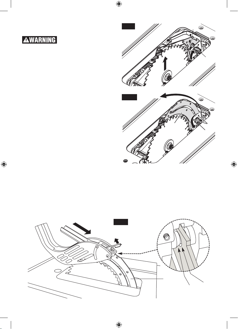
POSITIONING THE RIVING KNIFE
1. Remove table insert using table insert lock.
2. Raise the blade as high as it will go and set it
perpendicular to table (0° on bevel scale) (Fig.
10).
3. Rotate the riving knife release lever 1 clock-
wise, so that it points upward (Fig. 10).
4. Pull riving knife 2 towards release lever to dis-
engage it from the pins 3 (Fig. 11).
5. Slide the riving knife 2 up to its highest posi-
tion, so that it is directly over the center of the
blade (Fig. 11).
6. Align holes in riving knife with pins 3 and lock
the release lever 1 by rotating it counter-clockwise. Push/pull riving knife to verify that it is
locked in place (Fig. 11).
7. Replace table insert and lock.
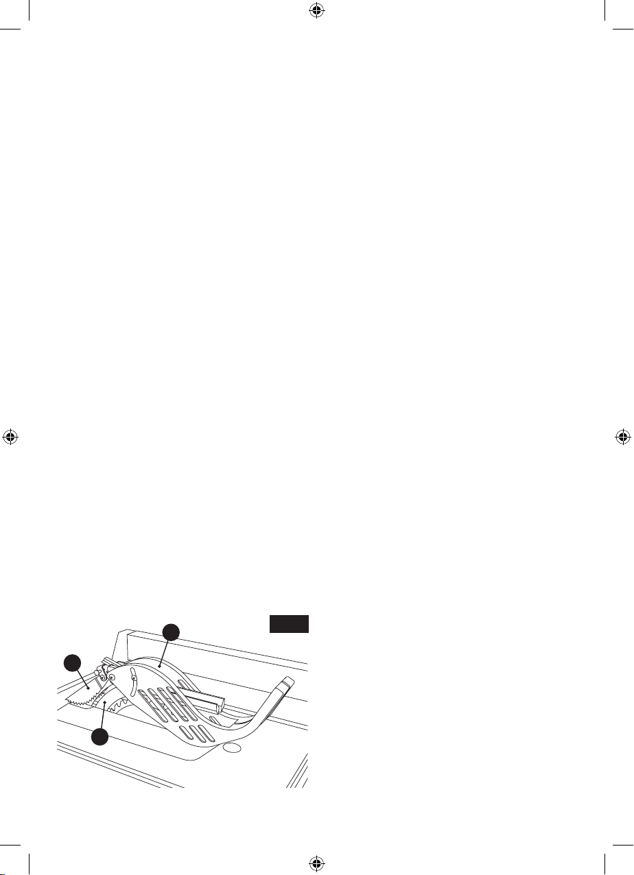
ATTACHING THE
GUARD ASSEMBLY
8. With one hand, hold the front of the barrier
guard assembly 4 by the metal “fork”. With the
other hand, hold the guard release lever 5 up
(Fig. 12).
9. Lower the rear of guard assembly and slip the
cross bar 6 into the rear notch 7 on top of the
riving knife 2 (Fig. 12).
Fig. 10
Fig. 11
2
1
2
3
1
4
Fig. 12
5
2
7
6
15
1600A009XC 09-15.indb 15 9/14/15 1:51 PM
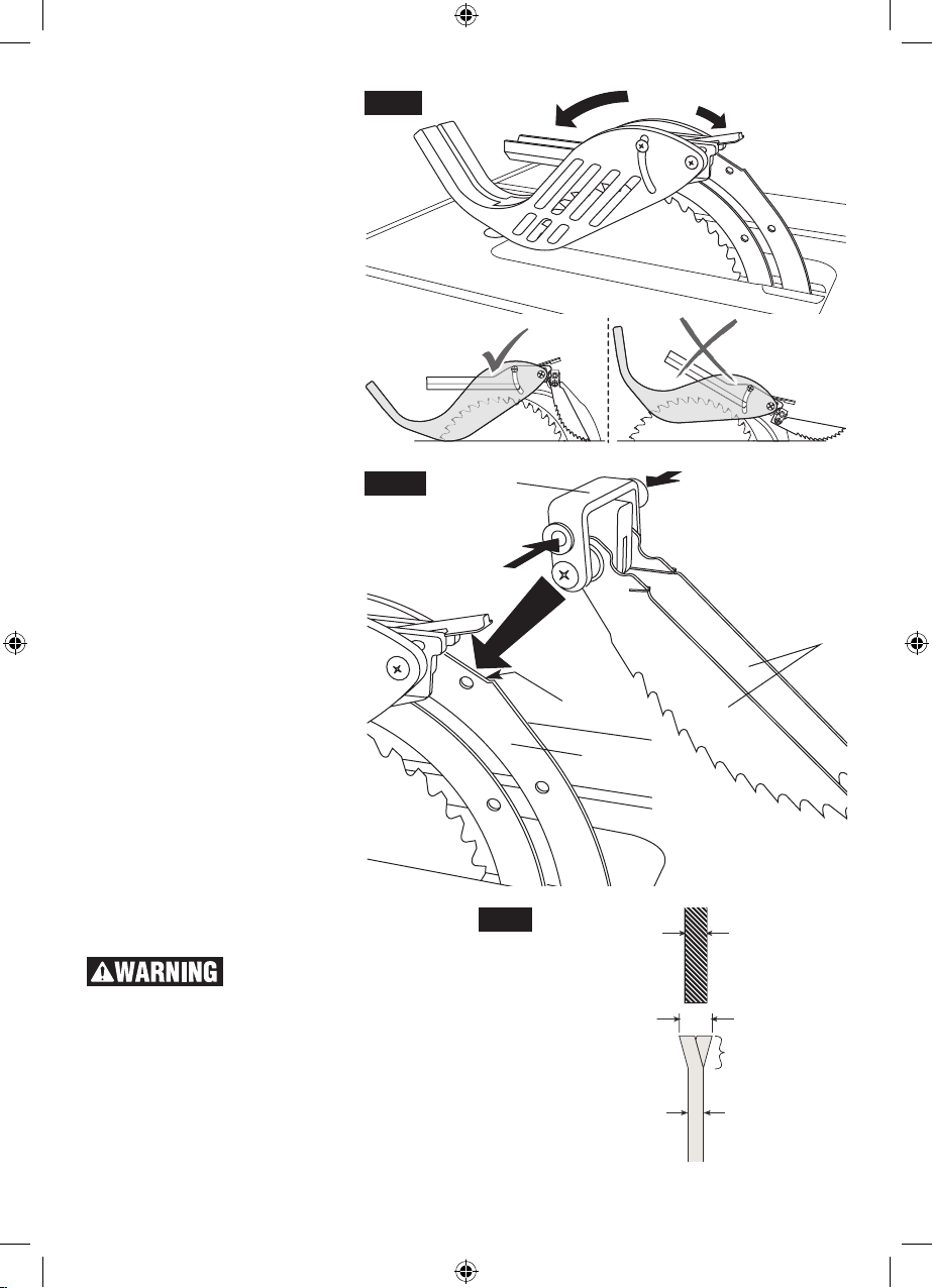
10. Lower the front of the guard as-
sembly 4 until the metal “fork” is
parallel with the table (Fig. 13).
11. Press down on the guard re-
lease lever 5 until you feel and
hear it snap into the locking position. Check that the guard assembly is properly and securely
connected (Fig. 13).
ATTACHING THE
ANTI-KICKBACK PAWLS
12. Attach the Anti-Kickback Pawls
7 into the flat recessed area 8 of
the riving knife 2 (Fig. 14).
13. Squeeze the compression pads
9 while nesting the device into
the flat area (Fig. 14).
14. Release the compression pads
such that the Anti-Kickback
Pawls lock onto the riving knife
immediately behind the guard
assembly. Check that the attachment pin is securely connected
into locking hole. Carefully raise
and lower the pawls 10 – when
letting go, the spring-loaded
pawls must come down and
contact the table insert (Fig. 14).
Hint: Position the Anti-Kickback
Pawls behind the flat recessed
area and slide it towards the front
until it drops into the recessed
area – then release the compression pins.
Note: The two attachments are
independent of each other, so the
Anti-Kickback Pawls can be attached before the Guard Assembly.
Fig. 13
Fig. 14
4
7
5
9
9
10
8
2
SELECTING AND
CHANGING THE BLADE
Fig. 15
.090” RIVING KNIFE
To prevent personal injury,
always disconnect plug
from power source before changing blades.
USING THE CORRECT BLADE
IMPORTANT: The saw blade provided on this
MUST BE .094” OR MORE
KERF WIDTH
BLADE TEETH
tool has a carbide-tipped kerf width of .128” and
a plate (body) thickness that is .086” thick. When
looking for a replacement blade, select one with
BLADE BODY PLATEMUST BE LESS THAN .090”
dimensions close to the original blade. This information may not be printed on the blades pack-
16
1600A009XC 09-15.indb 16 9/14/15 1:51 PM
aging. If not, check the manufacturers catalog or
website. Bosch offers an extensive line of Premium-Quality Professional Saw Blades that match
the requirements for this tool. You must select a
blade with a kerf width of .094” or more and a
plate (body) thickness .090” or less (Fig. 15).
The Active Response Technology™ injury mitigation system will function with a large variety of 10”
blades and body coatings. Coatings on the body
of the blade do not impact the system’s ability to
detect human/blade contact.
Make several cuts using
safe crosscutting techniques to wear off any varnish from the blade
teeth before beginning production work at
each blade change. Blades that have varnish
coating on the teeth reduce the ability of the Active Response Technology™ injury mitigation
system to detect contact between the operator
and the blade.
To reduce the risk of injury,
do not use extra thin kerf
saw blades. The kerf of the blade must be .094”
or more. Extra thin kerf saw blades (less than
.094”) may cause the work piece to bind against
the riving knife during cutting. It is recommended
that the kerf of the replacement blade used on
this saw be .094” or more.
To reduce the risk of injury,
do not use saw blades
made with a thick body plate. If the replace-
ment saw blade’s plate thickness is greater than
.088”, the riving knife would not properly serve as
an aid to reduce kickback. The replacement
blade’s plate thickness must be equal to or less
than .088”.
To reduce the risk of injury,
do not use blade “dampeners,” “stabilizers,” or “stiffening collars” on a
replacement blade. Use of these devices on
both sides will prevent the blade from being properly aligned with the riving knife, which may bind
the work piece during cutting and prevent the Active Response Technology™ system from working.
Cutting tool should not be
allowed to touch or wear
against the detection plate when the motor is
running. Contact between the detection plate
and the cutting tool will cause the system to activate. Damage to the detection plate may cause
delay or negate the ability of the Active Response
Technology™ System to detect the operator’s
contact with the blade. Always check to ensure
the blade spins freely before re-applying power to
the saw.
CHANGING THE BLADE
1. Turn elevation wheel clockwise until the blade
is up as high as it will go, remove table insert
21 by rotating the table insert lock 22, and use
the front edge to lift clear off the table (Fig. 4,
page 13).
Fig. 16
2
6
2. Slide and hold the arbor lock lever 2 towards
the back of the saw and slowly rotate blade by
hand until lock fully engages with the saw arbor
and stops rotation (Fig. 16). Loosen arbor nut
3 counter clockwise with the blade wrench 4
provided (Fig. 17). Set wrench aside and continue to loosen arbor nut 3 by hand and remove
arbor nut 3 and outer washer 5. Blade may now
Fig. 17
4
3
17
1600A009XC 09-15.indb 17 9/14/15 1:51 PM
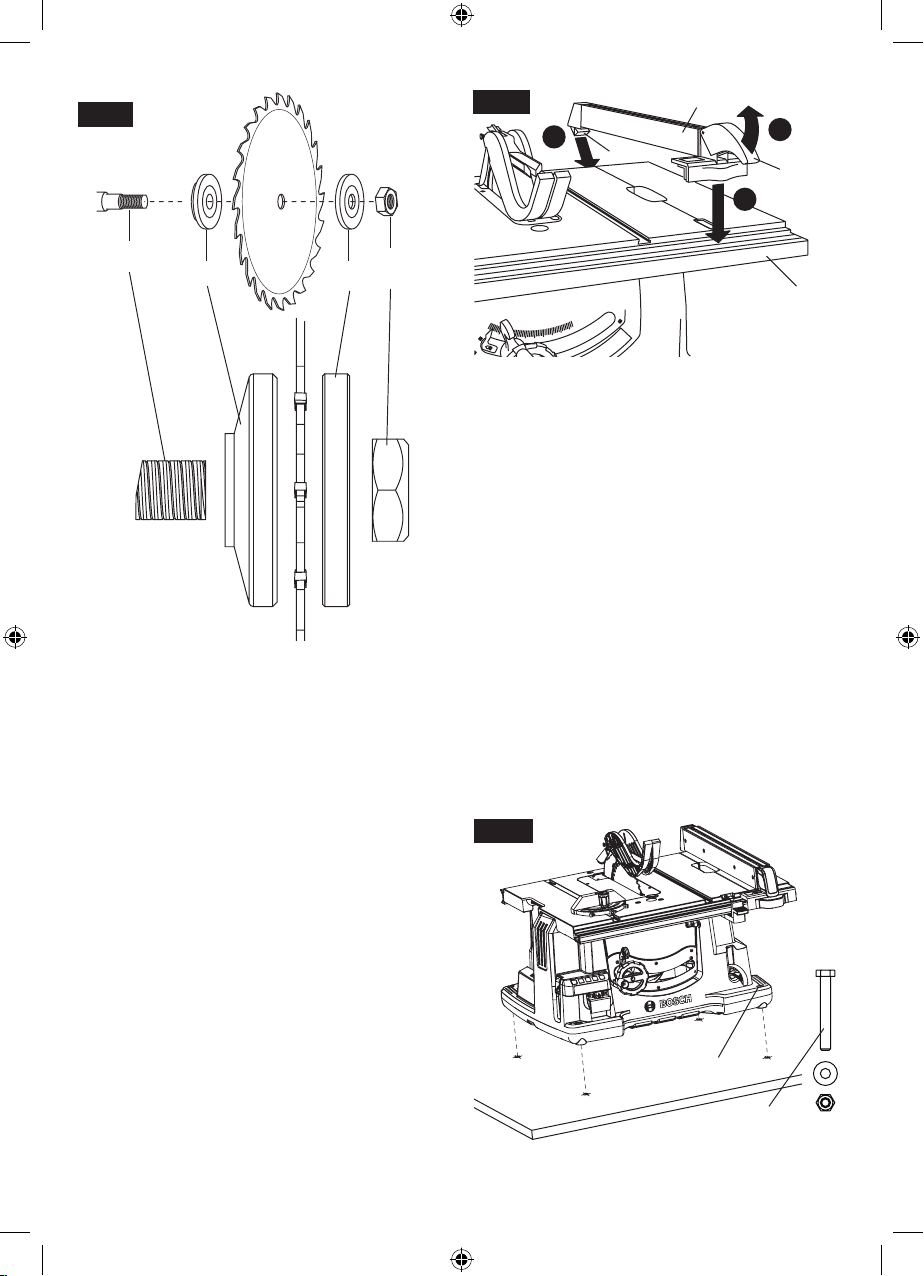
Fig. 18
Fig. 19
4
B
2
A
1
C
3
6
7
be removed or installed by sliding on or off arbor shaft 6 (Fig. 18).
3. Assemble inner washer 7 and new blade as
shown in figure 18, making certain the TEETH
OF THE BLADE ARE POINTING DOWN AT
THE FRONT OF THE TABLE. NOTE: The
printing on different saw blades is not always
on the same side.
4. Assemble outer washer 5 and arbor nut 3 as
shown in figure 17. While holding arbor lock lever 2 securely, tighten arbor nut 3 clockwise
with the wrench 4. (Fig. 16).
5. Position table insert 21 in pocket of table so
tabs 21a on table insert 21 are in slots in pocket of table and push down and secure in place
using table insert lock 22 (Fig.4, page 13).
3
5
ATTACHING RIP FENCE
1. Raise rip fence handle 1, so holding clamp 2 is
out far enough to fit on the table 3 and into “V”
groove located on the back of rear rail (Fig. 19).
2. Position the rip fence 4 over table 3 holding up
the front end, first engage holding clamp 2 with
rear rail.
3. Lower front end onto front rail 5.
5
MOUNTING THE TABLE SAW
If table saw is to be used in a permanent location,
it should be fastened securely to a firm supporting surface such as a stand or workbench, using
the four mounting holes 6 (Fig. 19).
1. If mounting to a workbench, the base should
be bolted securely using 5/16” hex bolts (not
included) through mounting holes 6.
Hint: If workbench is 3/4” thick, bolts will have
to be at least 3-1/2” long - if workbench is 1-1/2”
thick, bolts should be at least 4-1/2” long.
2. Locate and mark where the saw is to be mounted, relative to holes in the base of the tool.
3. Drill four (4) 3/8” diameter holes through workbench.
4. Place table saw on workbench aligning holes
in base with holes drilled in workbench.
5. Insert four (4) 5/16” dia. bolts through holes in
base and supporting surface; then secure with
(4) 5/16” flat washers and (4) 5/16” hex nuts.
Fig. 20
6
5/16” HEX BOLT,
WASHER &
HEX NUT (X4)
18
1600A009XC 09-15.indb 18 9/14/15 1:51 PM
Adjustments
ADJUSTING 0 AND 45 DEGREE POSI-
TIVE STOPS
Your saw is equipped with positive stops for fast
and accurate positioning of the saw blade at 0
and 45 degrees to the table.
The blade was adjusted at the factory. In order to
insure accurate cuts, this adjustment should be
rechecked. If adjustment is necessary, follow the
steps below.
To prevent personal injury,
always disconnect plug
from the power source when making adjustments.
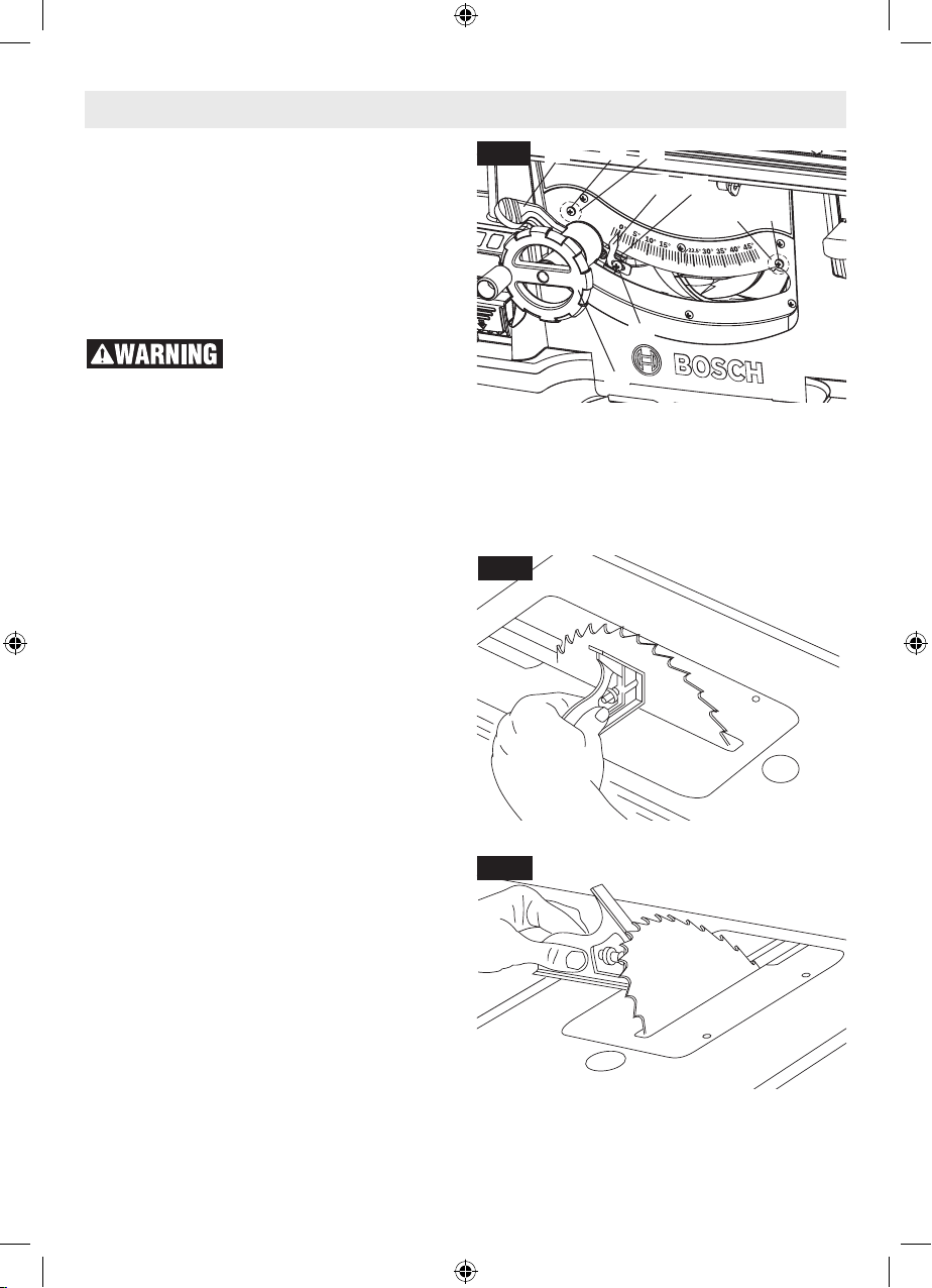
1. Turn elevation wheel 2 clockwise and raise
blade to maximum height (Fig. 21).
ADJUSTING 0 DEGREE POSITIVE
STOP:
2. Loosen the blade bevel lock handle 1 and push
the elevation wheel 2 to the left as far as possible and tighten the blade bevel lock handle 1
(Fig. 21).
3. Place a combination square on the table with
one end of the square against the blade as
shown (Fig. 22), and check to see if the blade
is 90 degrees to the table. If the blade is not
90 degrees to the table, loosen the blade bevel
lock handle 1, loosen 0 degree adjustment
screw 4, loosen 0 degree bevel stop cam 5 and
push the elevation wheel until the blade is 90
degrees to the table.
4. Tighten blade bevel lock handle 1, rotate the
bevel stop cam 5 until it touches the bevel stop
housing 7, then tighten 0 degree adjustment
screw 4.
5. Loosen adjustment screw 6 and adjust pointer
3 to indicate 0 degrees on the bevel scale.
ADJUSTING 45 DEGREE POSITIVE
STOP:
6. Loosen the blade bevel lock handle 1 and push
the elevation wheel 2 to the right as far as possible and tighten the blade bevel lock handle 1.
7. Place a combination square on the table with
one end of square against the blade as shown
(Fig. 23), and check to see if the blade is 45 degrees to the table. If the blade is not 45 degrees
to the table, loosen the blade bevel lock handle
1, loosen 45 degree adjustment screw 8, loosen 45 degree bevel stop cam 9 and push the
4
Fig. 21
8. Tighten blade bevel lock handle 1, rotate the
Fig. 22
Fig. 23
1
elevation wheel until the blade is 45 degrees to
the table.
45 degree bevel stop cam 9 until it touches the
bevel stop housing 7, then tighten 45 degree
adjustment screw 8.
5
3
7
9
8
6
2
19
1600A009XC 09-15.indb 19 9/14/15 1:51 PM
ADJUSTING BLADE PARALLEL TO
THE MITER GAUGE SLOTS
The blade was adjusted parallel to the miter
gauge slots at the factory. In order to insure accurate cuts and help prevent kickback, this adjustment should be rechecked. If adjustment is
necessary, follow the steps below.
To prevent personal injury,
always disconnect the plug
from the power source before making any adjustments.
1. Turn elevation wheel and raise blade as high
as it will go.
2. Select a point on the body of the saw blade that
is set to the left when viewing blade from the
front of saw, and mark 1 with a pencil (Fig. 24).
3. Place the base of a combination square against
the edge of the miter gauge slot, and extend
the sliding rule of square so it just touches the
marked point 1 on the body of the saw blade at
the rear of the table.
4. Rotate blade and check the same marked point
1 of the saw blade at the front of the table (Fig.
24).
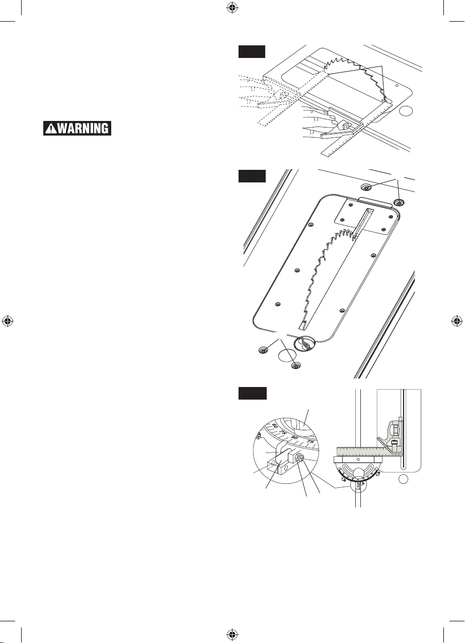
5. If the front and back measurements, shown
in Figure 24, are not identical, loosen the four
alignment bolts 2, located on the top of the
table one half turn at the front and rear of the
saw with hex wrench supplied with your saw
(Fig. 25). Carefully move the saw blade until the
blade is parallel to the miter gauge slot using
the combination square, and securely tighten
all four bolts.
MITER GAUGE ADJUSTMENT
To check your miter gauge accuracy, move the
miter gauge in line with blade and use a combination square to make sure the miter gauge body
is 90 degrees to the blade (Fig. 26). To adjust the
miter gauge for 90 degrees:
1. Loosen lock nut 3, adjustment screw 4, and
lock knob 5.
2. Flip stop plate 6 down.
3. Rotate miter gauge body until it is 90 degrees
to the blade.
4. Tighten lock knob 5.
5. Engage stop plate 6 and tighten adjustment
screw 4 until it contacts stop plate 6.
6. Tighten lock nut 3.
7. If pointer 7 is not pointing to 90 degrees, loosen
set screw 8 on side of miter gauge bar and ro-
Fig. 24
Fig. 25
2
Fig. 26
5
7
8
6
tate pointer 7 to 90 degrees mark. Tighten set
screw 8.
8. To adjust the miter gauge for 45 degrees left
and right, repeat steps 1-6, but use 45 degree
stops.
4
3
1
2
20
1600A009XC 09-15.indb 20 9/14/15 1:51 PM
ALIGNING RIP FENCE
To prevent personal injury,
always disconnect plug
from power source before making any adjustments. The rip fence must be parallel with the
Saw blade in order to prevent KICKBACK when
ripping.
Your table saw is equipped with a Self-Aligning,
Quick-Set rip fence. Once the adjustments below
have been made, the rip fence will self align when
the fence is locked into position.
NOTE: The blade must be parallel with the miter
gauge slots (see page 20) and be perpendicular
to table before proceeding with rip fence alignment.
To prevent personal injury,
always make sure the rip
fence is locked before making rip cuts.
1. Lift both guard barriers 2 to their up locked position.
2. Raise lock handle 1 and slide fence 3 until it
is alongside the saw blade, by lifting right side
pawl 4 above fence (Fig. 27). The fence should
touch the blade teeth at the front and rear of
the blade when locked. If fence does not touch
the teeth at front and rear of blade continue
with the following the steps:
3. Loosen the two screws 5 on the top front section of the rip fence using the included 5mm
hex wrench.
4. Move fence 3 until it touches the teeth and is
parallel to the blade.
5. Hold fence in place and lower lock handle,
check to make sure the fence stayed parallel to
the blade then tighten screws (Fig. 27).
6. Clamp rip fence to check if it holds securely at
front and rear. If rear is not clamped securely,
unclamp fence and turn rear clamp adjustment
screw 6 clockwise for increased clamping. Try
clamping the fence to verify if it self-aligns and
clamps tightly at the front and rear. Overtightening of the rear clamp adjustment screw 6 will
cause the rip fence to be non-self aligning (Fig.
27). Overtightening may cause friction or “chatter” when fence is moved side to side.
RIP FENCE POINTER ADJUSTMENT
The distance of the rip fence body from the blade
when ripping on the right side of the blade is determined by lining the pointer 7 with the desired
dimension on the scale 8 (Fig. 28).
TO SET THE RIP FENCE POINTER:
1. Lift both guard barriers 2 to their up locked position (Fig. 27).
2. Raise lock handle 1 and slide fence 3 until it
is alongside the saw blade, by lifting right side
pawl 4 above fence (Fig. 27).
3. Loosen pointer adjustment screw 9, adjust
pointer 7 to “0” mark on lower scale 8, then re-
tighten screw 9 (Fig. 28).
Fig. 27
6
4
2
5
Fig. 28
1
13
10 11 12 13
Changing to
Table Pointer
3
7 98
21
1600A009XC 09-15.indb 21 9/14/15 1:51 PM
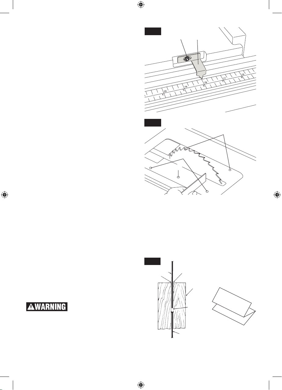
TABLE POINTER ADJUSTMENT
If an adjustment to the table pointer is necessary,
loosen pointer adjustment screw 1, adjust pointer
2 and tighten screw 1 (Fig. 29). The table pointer
should always be adjusted relative to fence pointer.
1. Adjust fence pointer to (zero) – see “Rip Fence
Pointer Adjustment”.
2. Slide fence to the right until it hits the stop plate
on front rail and lock fence in place.
3. Look at fence pointer and note measurement
on lower scale (at or near 12.75”).
4. Adjust the table pointer 2 to the same reading on upper scale as that shown on the fence
pointer. Both pointers must agree when fence
is at this position.
Example: If fence pointer is at 13-9/16”, then table
pointer should also be set at 13-9/16”.
ADJUSTING THE TABLE INSERT
The table insert includes five (5) adjustment
screws 3 to set the height (Fig. 30). Place the insert into the table. Place a straight edge (such as
the metal ruler from a combination square) across
the table top and insert top – the surfaces should
be at the same level. Alternately, the front edge
may be below the table top by the thickness of
dollar bill folded twice. Place the bill between the
insert and straight edge to check. The rear edge
may be proud of the table by the same amount.
Place the bill between the table and straight
edge to check. If adjustment is necessary, use
flat head screwdriver to adjust all support screws.
First adjust corner adjustment screws 3 to get
the alignment described above. Then adjust the
center adjustment screw 3A such that it does not
change the table insert alignment.
RIVING KNIFE ALIGNMENT
IMPORTANT: The Riving Knife 1 must always be
in line with the Saw Blade 2. The Riving Knife 1
is thinner than the width of the Kerf 4 by approximately three thicknesses of paper 5 on each side
(Fig. 31). Note: The Kerf is the width of the cut
made by the teeth on the saw blade.
To prevent personal injury,
always disconnect plug
from power source before making any adjustments and when attaching or removing the
Smart guard System.
Fig. 29
Fig. 30
3A
Fig. 31
1
5
LOOKING DOWN ON
SAW
1
2
3
5
2
WORK
4
3
5
22
1600A009XC 09-15.indb 22 9/14/15 1:51 PM
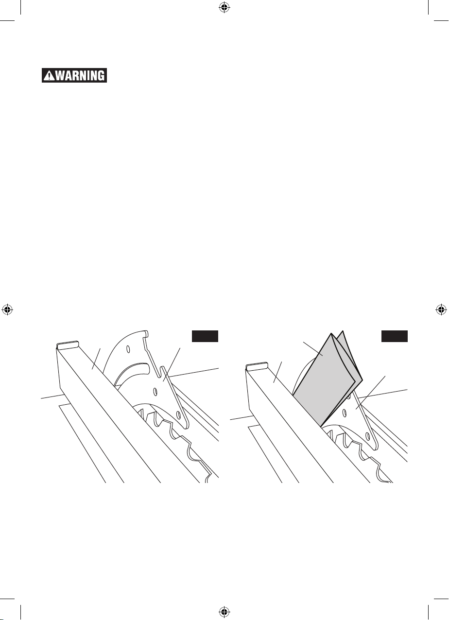
CHECKING RIVING KNIFE
ALIGNMENT
Check riving knife align-
ment to blade periodically
and make adjustments as necessary. Improp-
erly aligned riving knife may result in work piece
instability, loss of control, and KICKBACK. If the
riving knife is misaligned and cannot be adjusted,
do not attempt to operate the saw. Have a qualified service technician perform riving knife alignment.
1. Check that the blade is properly aligned paral-
lel with the miter gauge groove per instructions
listed under “Adjusting Blade Parallel to Miter
Gauge slots” (page 20) and adjust the blade if
necessary. Check that the rip fence is aligned
with the blade (see instructions listed under
“Aligning Rip Fence”, page 21) and adjust the
rip fence if necessary.
2. Raise the blade to the full height (up) position.
Raise the riving knife to its full up position (see
instructions listed under “Positioning The Riving Knife”, page 15). Remove the Anti-Kickback
Pawls and Guard Assembly from the riving
knife. Remove the insert plate.
3. Place the rip fence 3 on the left side of the table.
Carefully move the rip fence against the blade
so that the rip fence is parallel to the blade and
just touches the tips of the saw teeth. Lock the
rip fence and make sure the blade at the front
and back is still touching the rip fence (Fig 32).
4. Using the rip fence as a guide, check the riving knife alignment with the plane of the saw
blade. Since the riving knife is thinner, by approximately three thicknesses of paper on each
side, than the width of the blade’s KERF (Fig
31) you must make a temporary paper “spacing gauge“. Make two folds in a small piece
(6” X 6”) of ordinary newspaper making three
thicknesses. Place the paper spacing gauge 5
between the riving knife 1 and the rip fence 3
(Fig 33).
5. Repeat step 4 with the rip fence 3 on the right
of the blade and check with paper spacing
gauge 5 (Fig. 35).
6. If the paper spacing gauge does not fit between the rip fence and the riving knife per
steps 4 and 5 above, the riving knife is not
correctly aligned with the blade and must be
adjusted. If the riving knife needs adjustment
proceed to section Adjusting Riving Knife. If the
riving knife is correctly aligned with the blade
then no adjustment is necessary.
NOTE: The Riving Knife has been properly
aligned at the factory - Check the alignment before making any adjustments.
13
Fig. 32
5
3
Fig. 33
1
23
1600A009XC 09-15.indb 23 9/14/15 1:51 PM
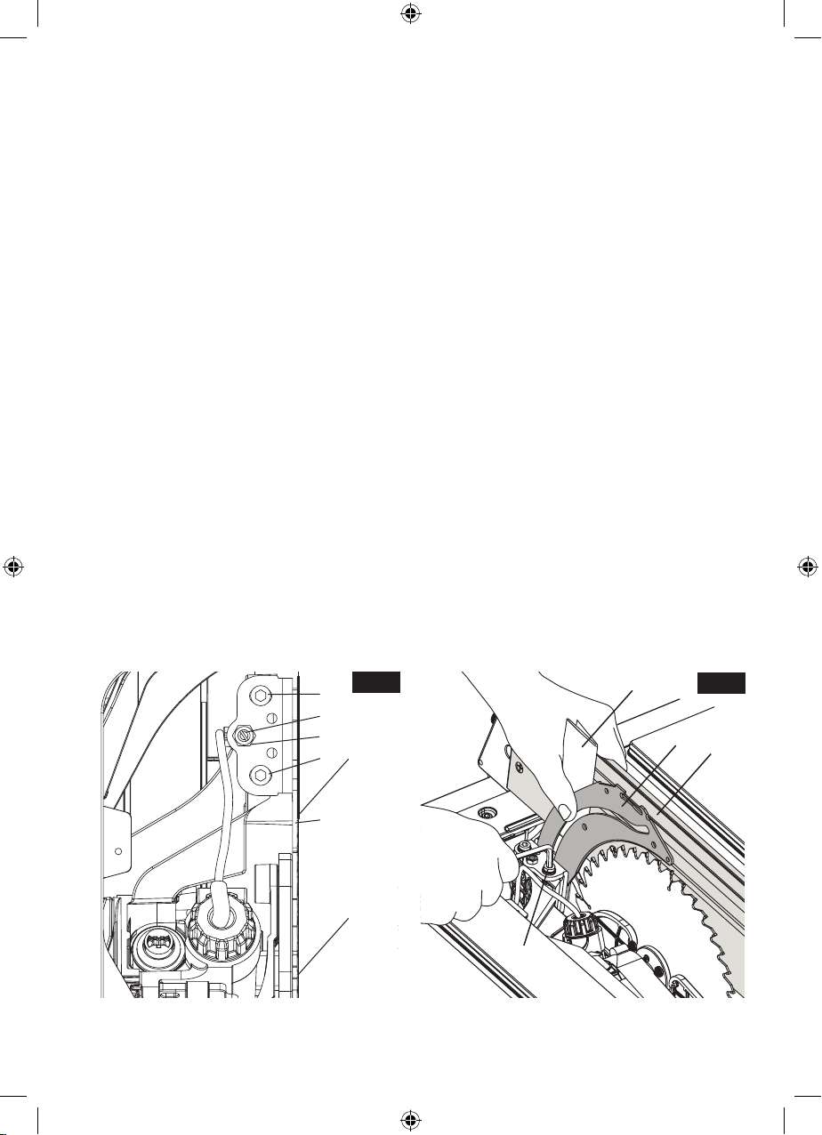
ADJUSTING RIVING KNIFE
1. Check that the blade is properly aligned parallel with the miter guage groove per instructions
listed under “Adjusting Blade Parallel to the Miter Gauge Slots (page 20) and adjust the blade
if necessary. Check that the rip fence is aligned
with the blade (see instructions listed under
“Aligning Rip Fence” on page 21) and adjust
the rip fence if necessary.
2. Raise the blade to the full height (up) position.
Raise the riving knife to its full up position (see
instructions listed under “Positioning The Riving Knife”, page 15). Remove the Anti-Kickback
Pawls and Guard Assembly from the riving
knife. Remove the insert plate.
3. Place the rip fence 3 on the left side of the table.
Carefully move the rip fence against the blade
so that the rip fence is parallel to the blade and
just touches the tips of the saw teeth. Lock the
rip fence and make sure the blade at the front
and back is still touching the rip fence (Fig. 32).
4. Loosen Hex Nut 6 with 10mm open end wrench
(Fig. 34). Slightly loosen Clamping Screws
8 (1/4-1/2 turns) using a 5mm hex wrench
provided with table saw (stored in left side of
base). Loosen Set Screw 7 using a flat screwdriver (Fig. 34).
5. Make two folds in a small piece (6“ X 6“) of
ordinary newspaper making three thicknesses.
Paper 5 is used as a “Spacing Gauge”.
NOTE: The spacing instructions above are based
on using a standard kerf blade (.128” kerf on the
Bosch blade included). If a smaller kerf blade is
used, adjust the paper spacer. For instance, if the
kerf of the replacement blade is near .100”, use 1
thickness of paper as a spacer; if the kerf is near
.110”, use 2 thicknesses.
6. Place the paper spacing gauge 5 between the
riving knife 1 and the rip fence 3 (Fig 35).Hold
or clamp Riving Knife and paper firmly against
Fence (Fig. 35).
a. Lightly tighten the clamp screws 8.
b. Remove the paper - Slide fence away from
blade.
c. Slowly turn the Set Screw 7 while watching
the Riving Knife tilt until it is in line with the
blade.
d. Recheck squareness of riving knife to table
by sliding fence against blade. Readjust if
necessary.
7. After completing adjustments:
a. Lightly tighten hex nut 6 (hold set screw posi-
tion with screwdriver while tightening nut).
b. Fully tighten Clamp Screws 8 with hex
wrench. Then fully tighten the hex nut.
IMPORTANT: The riving knife must always be
INLINE with the saw blade body when blade is at
any bevel angle. Replace the Table Insert Plate,
Barrier Guard Assembly and Anti-Kickback Pawls
before making cuts.
Fig. 34
8
5
Fig. 35
7
6
5
8
1
3
1
2
8
24
1600A009XC 09-15.indb 24 9/14/15 1:51 PM
Basic Table Saw Operation
USING THE ACTIVE RESPONSE
TECHNOLOGY™ INJURY MITIGATION
SYSTEM.
The Active Response Technology™ that is integral to the table saw is intended to be used together with the Smart Guard system to provide
the operator the greatest level of protection.
These two elements must be used together for
all cuts except those that require elements of the
Smart Guard to be removed (i.e. non-through
cuts). Any Smart Guard components that need
to be removed to complete a cut should be immediately reinstalled when finished. Always remember that the best accident prevention is the
operator’s use of common sense and alertness at
all times when using the table saw.
The Active Response Technology™ injury mitigation system is designed to function without limiting the performance or versatility of the table saw.
This system continually monitors the saw blade
for contact with the operator. If a contact is made
with the operator the blade will retract under the
table to reduce injury severity to the operator.
The information panel includes a lighted display
that indicates saw status. Under normal conditions the system turns on a green light above
the power switch. The saw can be used normally
once the green light is illuminated. If the green
light is not on or a blue or red light is on, then refer
to the troubleshooting section on page 45. When
cutting electrically conductive materials the tool
can be placed in bypass mode indicated by the
yellow light.
This system is designed to accommodate 25 system actuations before needing inspection by a
factory authorized service center. After 25 system
activations the tool will become inoperable until
service is performed by a factory authorized service center. It is recommended to perform service
before 25 system activations are reached. When
there is one remaining activation in the system
the blue service light will begin to flash when the
saw is plugged in. Additionally by using the NFC
function in the Bosch Toolbox App the system will
provide information regarding system activations.
Always use the Smart
Guard system to minimize
chances of contact between your body and
spinning blade. The Active Response Technol-
ogy™ injury mitigation system activates after
physical contact between the operator and the
blade is made. In case the Smart Guard system is
not in use the Active Response Technology™
system will mitigate the severity of injury due to
contact between operator and spinning blade.
The degree of injury mitigation will depend on
factors such as the direction and speed of the operator’s body movement at the time it contacts
the spinning blade.
Do not touch the blade until
stop. The Active Response Technology™ injury
mitigation system is armed and will activate anytime the blade is spinning, except at 240 revolutions per minute (RPM) or less, or when in bypass mode. The detection system is active at all
times the saw is connected to power and properly
initiated.
it comes to a complete
THE INFORMATION PANEL
In keeping with the straightforward function of the
system, the Information Panel has four lights to
explain the saws current status (Fig. 36).
Green (3) – The saw is ready to use and the
Active Response Technology™ injury mitigation
system will activate if the user contacts the blade.
Yellow (4) – This indicator lights when the user
disarms the system when using the bypass
switch 1.
Red (5) – An error is present that the user can
correct. For example, if the activation cartridge is
installed incorrectly.
Blue (6) – An error is present that can only be
corrected at a service center. For example, if the
Fig. 36
6
5
4
OFF
25
1
3
2
1600A009XC 09-15.indb 25 9/14/15 1:51 PM

tool has activated 25 times. Also, this light will
flash when service is recommended.
For additional information and Troubleshooting
see page 45.
CUTTING ELECTRICALLY
CONDUCTIVE MATERIALS
The Active Response Technology™ injury mitigation system monitors for change in the detection
plate signal caused by operator contacting the
blade. Some materials such as aluminum veneered plywood may mimic this effect.
Any metal, metal foil composite, or wet lumber
will cause the system to react if cut.
Allow the pressure treated
materials to air dry before
cutting in normal mode. Pressure treated lum-
ber is treated with chemicals that are electrically
conductive when wet.
POWER SWITCH
NOTE: This table saw has two safety features
that helps prevent accidental starting. The switch
can be locked in the off position, see “To prevent
unauthorized use” below. Also, the Active Response Technology™ system prevents the motor
from restarting if the switch is on when the plug is
connected to a power source.
To turn saw on: lift switch lever by pinching side
walls and lifting, or reach under the switch and
pull up. This action starts the saw (Fig. 37)
To turn off power: push switch lever down to its
original position (Fig. 36).
To prevent unauthorized use, the switch can
accommodate a padlock with a 3/16” or 1/4” diameter shackle (not provided with table saw),
(Fig. 36).
BYPASS SWITCH
Use bypass mode only
when cutting electrically
conductive materials. Using bypass mode
when not needed eliminates protection provided
by Active Response Technology™.
If a conductive material needs to be cut, the tool
has a bypass switch which disarms the Active
Response Technology™ injury mitigation system.
Press and hold the bypass switch A with one
hand, then turn on the power switch B with the
other. The saw blade will start to spin. The information panel will change from Green to Yellow
(Fig. 37).
Fig. 37
A
ON
B
When the power switch is turned off, the bypass
mode will be deactivated. Then the indicator will
change from Yellow to Green. The Active Response Technology™ will be active for the next
cut unless the bypass switch is pressed again.
To prevent unauthorized system bypass, the
switch can accommodate a padlock with a 3/16”
or 1/4” diameter padlock (not provided with table
saw), (Fig. 36).
NEAR FIELD COMMUNICATION (NFC)
INTERFACE
The Active Response Technology™ injury mitigation system can interface with smart phones
that have NFC functionality and the Bosch Power
Tools app installed.
Do not use the NFC function while the saw blade is
spinning. Distraction while cutting may result in
tool damage and serious personal injury.
To connect to the NFC, launch the Bosch Toolbox
App and click the “Connect to tool” button. Place
the smart phone against the Near Field Communication interface. The system will send all the
current data to phone.
The operator can use this to get maintenance
recommendations, reset procedures or troubleshooting procedures. You can also use this system to register the tool with Bosch. In case the
tool is stolen, this registration cannot be obscured
by defacing the nameplate.
26
1600A009XC 09-15.indb 26 9/14/15 1:51 PM
ELECTRONICALLY LOCKING THE
SAW
Using the NFC and a smart phone, the operator
can lock or unlock the saw’s motor. The system
ships unlocked. The user can program a fourdigit PIN, then set the lock mode.
Lock Modes:
Unlocked – Any user can use the tool. Green
light indicated.
Locked – The saw cannot be used until unlocked.
Red light indicated.
Timer – Set a duration for the working time in
the day. When time elapses, the system enters
Locked mode.
Single Use – Allow a single cut to be made.
SMART GUARD SYSTEM
The Bosch Smart Guard system is the primary
safety system of this table saw. The Smart Guard
system is supplemented by the Active Response
Technology™. The Active Response Technology™ provides injury mitigation protection when
the table saw is connected to power and smart
guard system is not in use when making special
cuts. Any Smart Guard components that need
to be removed to complete a cut should be immediately reinstalled when finished. Always remember that the best accident prevention is the
operator’s use of common sense and alertness at
all times when using the table saw.
The Bosch Smart Guard System has been designed for modularity, enabling the use of multiple combinations of the three main components
– Main barrier guards, Anti-Kickback Pawls, and
riving knife. Additionally, the riving knife can be
quickly adjusted to three positions (high, middle,
and stored), depending on the application requirement.
Component parts (Fig. 38):
2
3
1
Fig. 38
➊ Riving Knife
The Riving Knife is the central element of the
Bosch Smart Guard blade guarding system,
serving as the attachment point for both the Main
Barrier Guard and the Anti-Kickback Pawls. In the
event that the Main Barrier Guard and Anti-Kickback Pawls are removed, the Riving Knife maintains its functionality as material splitter, and is
adjustable to three positions. Because of this adjustability, the Riving Knife can be appropriately
positioned for all cutting applications.
➋ Main barrier guard
The main guard is comprised of a pair of plastic barriers attached to the metal upper barrier
guard. The side barriers (one to the left and one
to the right of the blade) operate independently
of one another, maintaining maximum blade coverage during cutting operations. The main guard
incorporates a quick-connect attachment point
and can be attached or removed from the blade
guarding system independent of the Anti-Kickback Pawls and Riving Knife.
Note: To best secure the main guard for transport, adjust the blade to its lowest position. This
keeps the guard tight to the table surface and
prevents damage related to the guard swinging
during transport.
➌ Anti-Kickback Pawls
In the event of kickback, the Anti-Kickback Pawls,
(also known as dogs, or pawls) are intended to
help prevent the board from being thrown in the
direction of the user. The sharp teeth of the pawls
are intended to “catch” the material in the event
of kickback.
ATTACHMENT/REMOVAL
(see pages 15 and 16 for detailed instructions)
The three primary components of the Smart
Guard blade guarding system are designed for
rapid attachment, adjustment, and/or removal
without the need for additional tools.
The Main Barrier Guard component can be
quickly attached and detached through the use
of a quick release lever. The guard is attached
by seating the crossbar into the top of the Riving
Knife and engaging the locking lever. Following
this process in reverse, the guard can be easily
removed for special operations such as dados or
rabbets.
The Anti-Kickback Pawls can be easily attached
by aligning the attachment pin with the hole in the
rear of the riving knife. It can be easily removed
by depressing the compression pads on either
27
1600A009XC 09-15.indb 27 9/14/15 1:51 PM
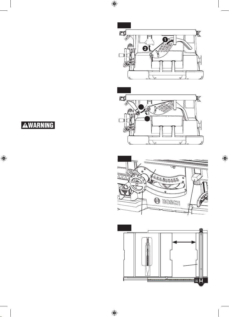
side of the Anti-Kickback Pawls and lifting it away.
The Riving Knife can be easily adjusted to one of
three heights by removing the table insert, raising
the blade to its full height and releasing the riving
knife release lever at the base of the Riving Knife.
The Riving Knife should be locked in its highest position for use with the Main Barrier Guard
and Anti-Kickback Pawls. It can be adjusted to
its middle position for non-through cuts and for
use as a material splitter without the Main Barrier
Guard and Anti-Kickback Pawls. In the event that
the Riving Knife cannot be used for a specific cut,
it can be adjusted to its lowest position, thus placing it 1” above the surface of the table (while the
blade is at its full height).
SYSTEM STORAGE
When not in use, the Main Barrier Guard and Anti-Kickback Pawls can be stored under the right
side table extension.
Use of all the components
of the Smart Guard System,
including Main Barrier Guard, Anti-Kickback
Pawls, and Riving Knife is highly recommended to provide protection against accidents
and injury.
1. Slide the Main Barrier Guard assembly (upside
down) up and back into the U-bracket at the
rear right side of the saw (Fig. 39).
2. Pivot the rear of the guard up and into the front
mounting bracket.
3. Lock the Main Barrier Guard assembly into
place in the same manner as you would attach
it to the Riving Knife (Fig. 40).
4. Attach the Anti-Kickback Pawls to the hanging
bracket in the same manner that it attaches to
the Riving Knife.
BLADE BEVEL CONTROL
Loosen blade bevel lock handle 1 counterclockwise (Fig. 41), slide the elevation wheel 2 until
pointer 3 is at desired angle and tighten blade
bevel lock handle 1 clockwise.
EXTENDING TABLE EXTENSION
To extend the table, raise the table extension lock
handle 4 (Fig. 41) and slide table extension 5 to
desired width (Fig 42). To secure table setting,
lower the lock handle 4.
Fig. 39
Fig. 40
Fig. 41
Fig. 42
4
3
1
3
2
4
5
28
1600A009XC 09-15.indb 28 9/14/15 1:51 PM
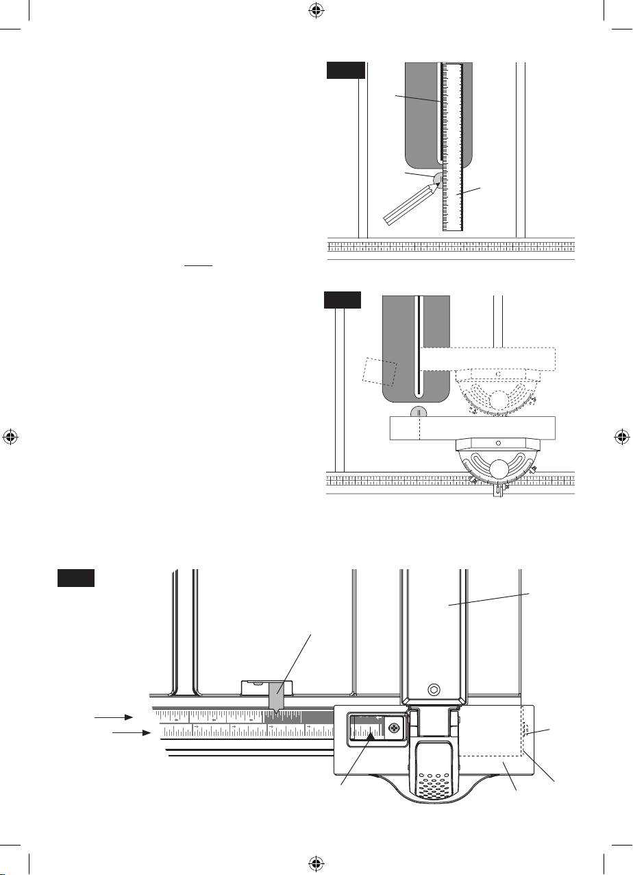
Changing to
Table Pointer
8910 11 12 13
15 14 13
PRE-CUT LOCATOR
Allows you to mark and locate exactly where the
blade will enter the work piece.
Always make sure table saw is turned off and unplugged.
Set blade 1 at 90 degrees square to table. Using
a straight edge and a soft pencil, place straight
edge 2 against both sides of blade and mark lines
on locator 3 (Fig. 43). These lines indicate the
“path” of the cut (kerf) made by the blade. When
cutting the work piece, line up mark on work
piece with the line on the disc (Fig. 44).
USING THE RIP FENCE POINTER
WHEN TABLE IS NOT EXTENDED
The rip fence pointer shows the distance from the
blade to rip fence through a convenient viewing
and magnifying window. Align rip fence pointer 4
with lower portion of scale 5. The lower scale can
be used for widths up to 12.75 inches (Fig. 45).
USING THE TABLE POINTER WHEN
TABLE IS EXTENDED
The upper portion of scale 6 is used for rip cut
12.75 to 25 inches. Align table pointer 7 with upper portion of scale 6 (Fig. 45).
MAKING RIP CUTS BEYOND 25 INCH-
ES WITHOUT THE USE OF SCALE
When positioning fence for maximum rip without
the use of scale, loosen screw 8 and lower plate
9 below the head 10 of the rip fence 11 (Fig. 45).
DO NOT rip or cut dados with the fence beyond
this position because it cannot be locked.
Fig. 43
Fig. 44
1
3
2
Fig. 45
11
7
6
5
4
10
8
9
29
1600A009XC 09-15.indb 29 9/14/15 1:51 PM
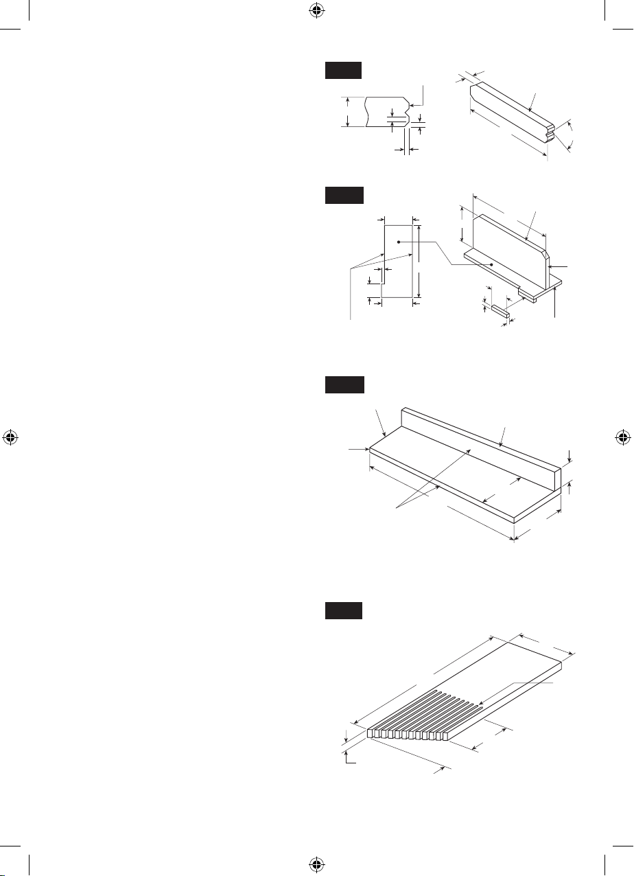
WORK HELPERS
Before cutting any wood on your saw, study all of
the “Basic Saw Operations”.
Notice that in order to make some of the cuts, it is
necessary to use certain devices, “Work Helpers”,
like the Push Stick, the Push Block and the Auxiliary Fence, which you can make yourself.
After you have made a few practice cuts, make
these “helpers” before starting any projects. Make
the “Push Stick” first.
PUSH STICK AND PUSH BLOCK
Make the Push Stick 1 using a piece of 1 x 2 as
shown (Fig. 46).
Make the Push Block 2 using pieces of 3/8” plywood 3 and 3/4” hardwood 4 (Fig. 47). For proper
use of push block (see page 36).
The small piece of wood, 3/8” x 3/8” x 2-1/2”,
should be GLUED to the plywood. DO NOT USE
NAILS. This is to prevent dulling the saw blade in
the event you mistakenly cut into the Push Block.
Position the handle in the center of the plywood
and fasten together with glue and wood screws.
Use a push stick whenever the fence is 2 inches
or more from the blade. Use a push block when
the operation is too narrow to allow the use of a
push stick. For proper use, see page 36.
Both a push stick or block should be used in the
place of the user’s hand to guide the material only
between the fence and blade.
When using a push stick or push block, the trailing end of the board must be square. A push stick
or block against an uneven end could slip off or
push the work away from the fence.
AUXILIARY FENCE
Make one using pieces of 3/8” plywood 3 and 3/4”
hardwood 4. Fasten together with glue and woodscrews (Fig. 48).
NOTE: Since the Push Block 2 is used with the
Auxiliary Fence 5, the 4-3/4” dimensions must be
held identical on both the pieces.
MAKING A FEATHERBOARD
Fig. 49 illustrates dimensions for making a typical
feather board. It should be made from a straight
piece of wood that is free of knots or cracks. Kerf
5 should be about 1/4” apart (fig. 49).
Fig. 46
1-1/2
Fig. 47
2-1/2
THESE EDGES
MUST BE PARALLEL
Fig. 48
3
5
THIS FACE
AND THIS EDGE
MUST BE PARALLEL
Fig. 49
3/4
WORK PIECE
END
1/4
1/4
1/4
4-3/4
12
3/8
5-1/8
25
21-1/2
4-1/2
2-1/2
3/8
3/4
5
15
4-3/4
1
45°
NOTCH
4
12
2
3/8
3
4
2-1/4
5-1/2
8
5
NOTE: ALL DIMENSIONS IN INCHES
30
1600A009XC 09-15.indb 30 9/14/15 1:51 PM
 Loading...