

Bosch GSR 18 VE-2, GSR 24 VE-2, GSB 24 VE-2, GSB 18 VE-2 Operating Instructions Manual
Bedienungsanleitung
Operating Instructions
Instructions d’emploi
Instrucciones de servicio
Manual de instruções
Istruzioni d’uso
Gebruiksaanwijzing
Betjeningsvejledning
Bruksanvisning
Brukerveiledningen
Käyttöohje
Oδηγία χειρισµού
Kullanım kılavuzu
Deutsch
English
Français
Español
Português
Italiano
Nederlands
Dansk
Svenska
Norsk
Suomi
Eλληνικά
Türkçe
GSR 18 VE-2
GSB 18 VE-2
GSR 24 VE-2
GSB 24 VE-2

2 • 2 609 932 048 • 03.02
2 608 572 062
1/2" 20 UNF
2 607 000 205
2 607 000 239*
PH Nr. 2
2 607 000 248*
PZ Nr. 2
2 607 000 258*
T 20
2 607 000 317*
SW 3 mm
2 607 000 221*
0,8 x 5,5 mm
2,0 Ah (NiCd):
2 607 335 266 (18 V)
2 607 335 446 (24 V)
2 605 439 014
2 605 439 013
2 605 439 012
2 605 439 015
2 605 438 411
*
3 ×
1 609 200 392
2 602 025 110
AL 60 DV 2425
(7,2–24 V)
2 607 224 426 (EU)
2 607 224 428 (UK)
2 607 224 430 (AUS)
AL 15 FC 2498
(7,2–24 V)
2 607 224 484 (EU)
2 607 224 486 (UK)
2 607 224 488 (AUS)
2 607 000 204

3 • 2 609 932 048 • 03.02
GSB 18 VE-2
GSB 24 VE-2
GSR 18 VE-2
GSR 24 VE-2
1
2
3
4
5
6
7
8
9
10
11

Deutsch - 1
1
Gangwahlschalter
2
Zusatzgriff
3
Drehmoment-Einstellring
4
Schnellspannbohrfutter
5
Schraube
6
Akku
7
Akku-Entriegelungstaste
8
Schrauberklinge
9
Ein-/Ausschalter
10
Drehrichtungsumschalter
11
Softgrip
Abgebildetes oder beschriebenes Zubehör gehört
teilweise nicht zum Lieferumfang.
Messwerte ermittelt entsprechend EN 50 144.
GSR 18 VE-2/GSR 24 VE-2:
Der A-bewertete Schalldruckpegel des Gerätes
ist typischerweise kleiner als 70 dB (A).
Der Geräuschpegel beim Arbeiten kann
85 dB (A) überschreiten.
Gehörschutz tragen!
Die Hand-Arm-Vibration ist typischerweise niedriger als 2,5 m/s
2
.
GSB 18 VE-2/GSB 24 VE-2:
Der A-bewertete Geräuschpegel des Gerätes beträgt typischerweise: Schalldruckpegel 89 dB (A);
Schallleistungspegel 102 dB (A).
Gehörschutz tragen!
Die bewertete Beschleunigung beträgt typischerweise 7,5 m/s
2
.
Gerätekennwerte
Akku-Bohrschrauber GSR 18 VE-2 GSR 24 VE-2
Bestellnummer 0 601 951 3.. 0 601 951 2..
Akku-Schlagbohrschrauber GSB 18 VE-2 GSB 24 VE-2
Bestellnummer 0 601 952 3.. 0 601 952 2..
Leerlaufdrehzahl
1. Gang [min-1] 0–400 0–510 0 –520 0–450
2. Gang [min-1] 0–1 400 0–1 800 0 –1 850 0–1 500
Drehmomenteinstellbereich [Nm] 1–10 1–10 1–10 1–10
Max. Drehmoment in
Stellung „ “:
Weicher Schraubfall [Nm] 30 25 30 38
Harter Schraubfall [Nm] 55 50 55 65
Bohr-Ø Stahl, max. [mm] 14 13 14 15
Bohr-Ø Holz, max. [mm] 36 35 36 38
Bohr-Ø Stein, max. [mm] – 16 17 –
Schrauben-Ø, max. [mm] 10 10 12 14
Bohrfutterspannbereich [mm] 1,5–13 1,5–13 1,5–13 1,5–13
Auto-Lock
● ● ● ●
Bohrspindelgewinde 1/2" 1/2" 1/2" 1/2"
Gewicht (ohne Zubehör), ca. [kg] 2,5 2,7 3,1 2,8
Akku NiCd NiCd NiCd NiCd
Temperaturüberwachung NTC NTC NTC NTC
Nennspannung [V=] 18 18 24 24
Kapazität [Ah] 2,0 2,0 2,0 2,0
Gewicht, ca. [kg] 0,95 0,95 1,3 1,3
Bitte die Bestellnummer Ihrer Maschine beachten. Die Handelsbezeichnungen einzelner Maschinen können variieren.
Geräteelemente Geräusch-/Vibrationsinformation
4 • 2 609 932 048 • TMS • 16.01.03

Deutsch - 2
Gefahrloses Arbeiten mit dem
Gerät ist nur möglich, wenn Sie
die Bedienungsanleitung und
die Sicherheitshinweise vollständig lesen und die darin ent-
haltenen Anweisungen strikt befolgen. Zusätzlich müssen die allgemeinen
Sicherheitshinweise im beigefügten Heft befolgt werden.
■
Schutzbrille tragen.
■
Bei langen Haaren Haarschutz tragen. Nur mit
eng anliegender Kleidung arbeiten.
■
Vor jeder Benutzung Gerät und Akku überprüfen. Werden Schäden festgestellt, Gerät nicht
weiter benutzen. Reparatur nur von einem
Fachmann durchführen lassen. Gerät nie
selbst öffnen.
■
Vor allen Arbeiten am Gerät (z. B. Wartung,
Werkzeugwechsel, usw.) sowie bei dessen
Transport und Aufbewahrung den Drehrichtungsumschalter stets in Mittelstellung
bringen.
Sonst besteht Verletzungsgefahr bei
unbeabsichtigtem Betätigen des Ein-/Ausschalters.
■
Überzeugen Sie sich vor der Benutzung vom
sicheren Sitz des Akkus im Gerät.
■
Verwenden Sie geeignete Suchgeräte, um
verborgene Versorgungsleitungen aufzuspüren, oder ziehen Sie die örtliche Versorgungsgesellschaft hinzu.
Kontakt mit Elektroleitungen kann zu Feuer
und elektrischem Schlag führen. Beschädigung einer Gasleitung kann zur Explosion führen. Eindringen in eine Wasserleitung verursacht Sachbeschädigung.
■
Verwenden Sie Ihr Gerät nur mit dem Zusatzgriff
2
.
■
Beim Arbeiten das Gerät immer fest mit beiden
Händen halten und für einen sicheren Stand
sorgen.
■
Gerät gut festhalten: Beim Festziehen können
kurzzeitig hohe Reaktionsmomente auftreten.
■
Sichern Sie das Werkstück.
Ein mit Spannvorrichtungen oder Schraubstock festgehaltenes Werkstück ist sicherer gehalten als mit Ihrer Hand.
■
Niemals Kindern die Benutzung des Gerätes
gestatten.
■
Bosch kann nur dann eine einwandfreie Funktion des Gerätes zusichern, wenn das für dieses Gerät vorgesehene Original-Zubehör verwendet wird.
Akku und Ladegerät
■
Unbedingt die beiliegende Bedienungsanleitung des Ladegerätes lesen!
■
Akku nicht öffnen sowie vor Stoß schützen.
Trocken und frostsicher aufbewahren.
■
Erwärmten Akku vor dem Laden abkühlen lassen.
■
Akku vor Hitze und Feuer schützen: Explosionsgefahr! Akku nicht auf Heizkörper ablegen
oder längere Zeit starker Sonneneinstrahlung
aussetzen, Temperaturen über 50 °C schaden.
■
Den Akku nicht in den Hausmüll, ins Feuer
oder ins Wasser werfen.
GSB:
Das Gerät ist bestimmt zum Eindrehen und
Lösen von Schrauben, zum Bohren in Holz, Metall, Keramik und Kunststoff und zum Schlagbohren in Ziegel, Beton und Gestein.
GSR:
Das Gerät ist bestimmt zum Eindrehen und
Lösen von Schrauben sowie zum Bohren in Holz,
Metall, Keramik und Kunststoff.
Der Zusatzgriff
2
bietet zusätzliche Sicherheit, da
beim Schlagbohren, Bohren mit großen Durchmessern und Schrauben ruckartige Reaktionsmomente auftreten können.
Den Zusatzgriff
2
abhängig von der Arbeitsweise
rechts oder links am Gerät mit der Schraube
5
montieren.
Akku laden
Ein neuer oder längere Zeit nicht verwendeter
Akku bringt erst nach ca. 5 Lade- und Entladezyklen seine volle Leistung.
Zur Entnahme des Akkus
6
die Entriegelungstas-
ten
7
drücken und den Akku nach unten heraus-
ziehen. Keine Gewalt anwenden.
Zu Ihrer Sicherheit
Bestimmungsgemäßer Gebrauch
Zusatzgriff
Vor der Inbetriebnahme
5 • 2 609 932 048 • TMS • 16.01.03
Deutsch - 3
Der Akku ist mit einer NTC-Temperaturüberwachung ausgestattet, welche Ladung nur im Temperaturbereich zwischen 0 °C und 45 °C zulässt.
Dadurch wird eine hohe Akku-Lebensdauer erreicht.
Eine wesentlich verkürzte Betriebszeit nach der
Aufladung zeigt an, dass die Akkus verbraucht
sind und ersetzt werden müssen.
■
Hinweise zum Umweltschutz beachten.
Das Bohrfutter öffnen, bis das Werkzeug eingesetzt werden kann. Das Werkzeug einsetzen.
Die Hülse des Schnellspannbohrfutters
4
von
Hand kräftig zudrehen bis kein Überrasten
(„Klick“) mehr hörbar ist. Das Bohrfutter wird dadurch automatisch verriegelt.
Drehen Sie die Hülse in Gegenrichtung um das
Werkzeug zu entnehmen.
Schrauben
Die Schrauberklinge 8 direkt in das Bohrfutter
einspannen oder bei Verwendung von Schraubendrehereinsätzen (Bits) zusätzlichen Universalbithalter verwenden.
Akku einsetzen
Den Drehrichtungsumschalter
10
auf Mitte = Ein-
schaltsperre stellen und den geladenen Akku
6
in
den Griff einrasten lassen.
Ein-/Ausschalten
Zur
Inbetriebnahme
des Gerätes den Ein-/Aus-
schalter
9
drücken.
Die Maschine läuft je nach Druck
auf den Ein-/Ausschalter
9
mit variabler Drehzahl zwischen 0 und Maximum. Leichter Druck bewirkt eine
kleine Drehzahl und macht somit
einen sanften, kontrollierten Anlauf
möglich. Das Gerät nicht so stark
belasten, dass es zum Stillstand
kommt.
Zum
Ausschalten
des Gerätes den Ein-/Aus-
schalter
9
loslassen.
Auslaufbremse
Beim Loslassen des Ein-/Ausschalters 9 wird das
Bohrfutter abgebremst und dadurch das Nachlaufen des Werkzeugs verhindert.
Bei Schraubarbeiten den Ein-/Ausschalter
9
erst
dann loslassen, wenn die Schraube bündig in
das Material eingedreht ist. Der Schraubenkopf
dringt dann nicht in das Material ein.
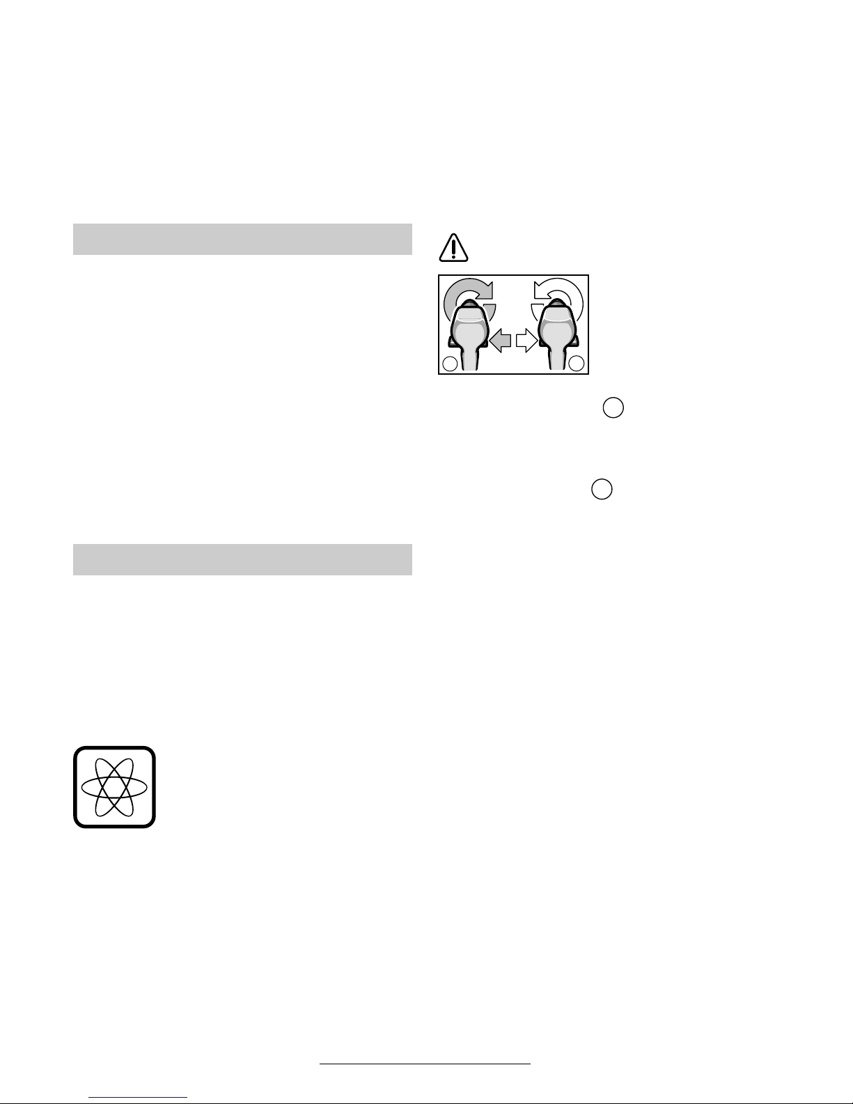
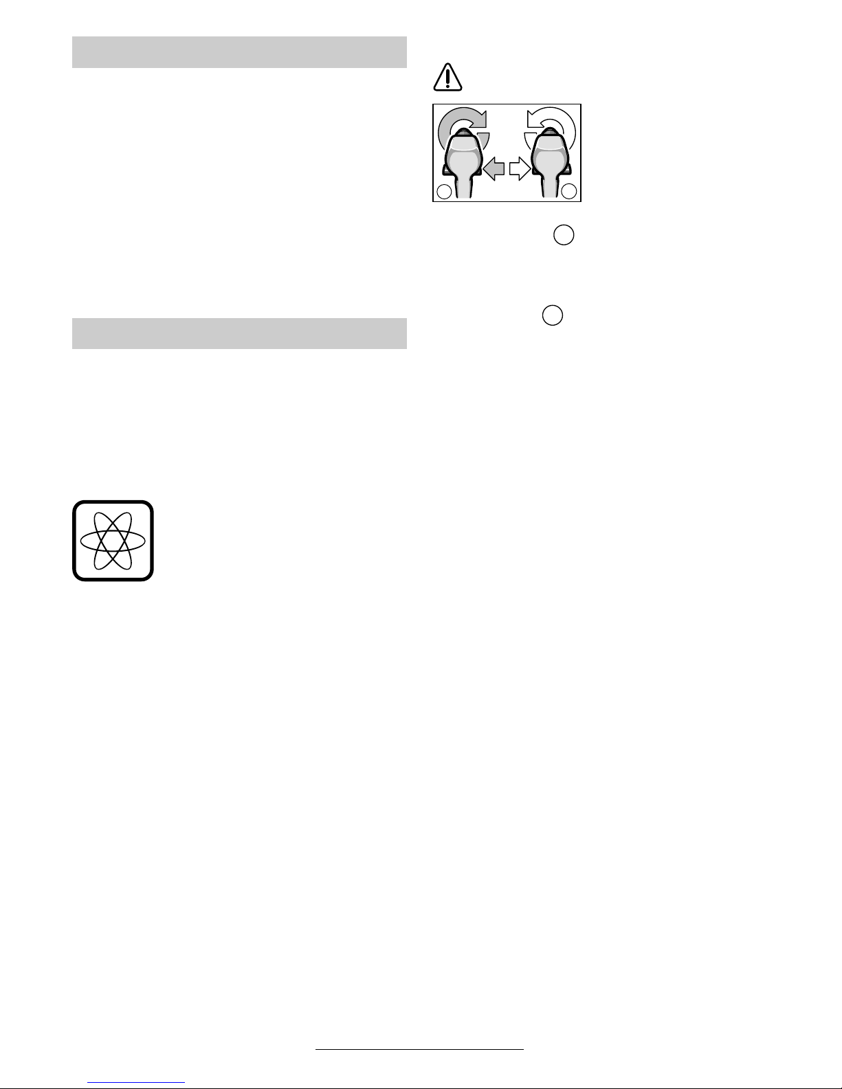
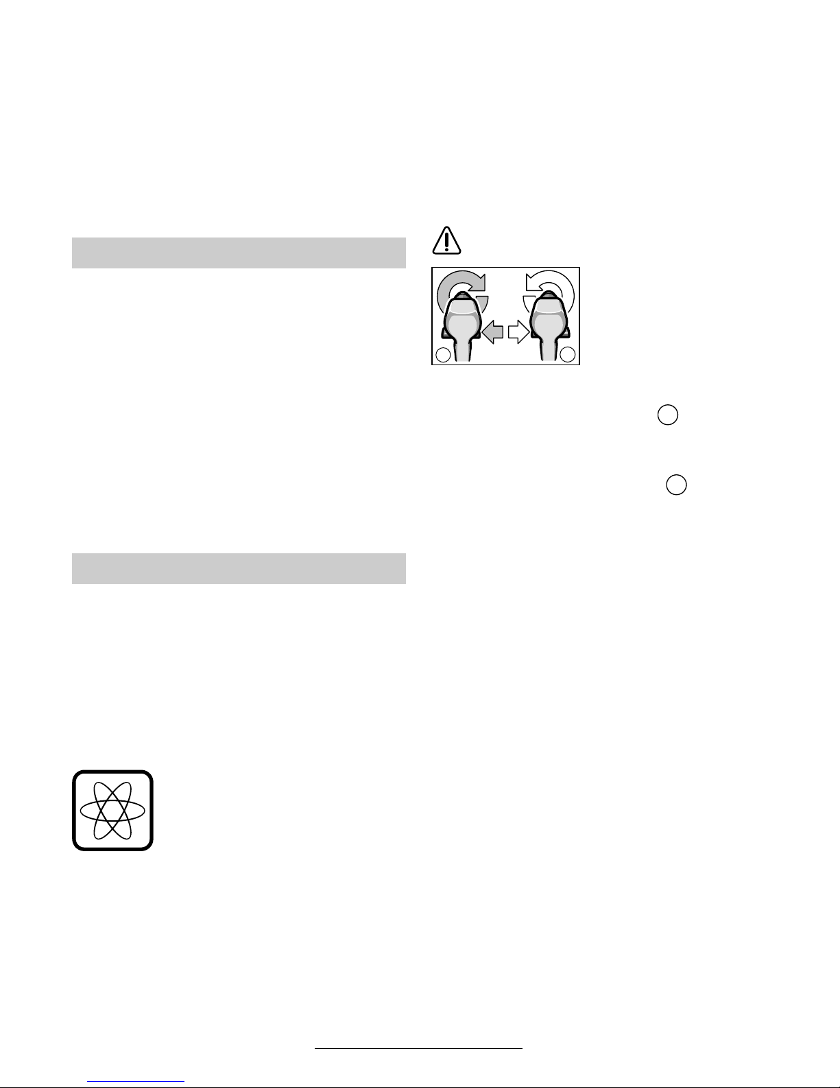
Umschalten der Drehrichtung
Den Drehrichtungsumschalter 10 nur
bei Stillstand betätigen.
Mit dem Drehrichtungsumschalter
10
wird die
Drehrichtung der Maschine umgeschaltet. Bei
betätigtem Ein-/Ausschalter
9 ist dies jedoch
nicht möglich.
Drehrichtung rechts ( )
Den Drehrichtungsumschalter nach links bis zum
Anschlag durchdrücken (Normalbetrieb: Bohren,
Eindrehen von Schrauben etc.).
Drehrichtung links ( )
Den Drehrichtungsumschalter nach rechts bis
zum Anschlag durchdrücken (Lösen bzw. Herausdrehen von Schrauben und Muttern).
Mechanische Gangwahl
Mit dem Gangwahlschalter 1 können zwei Drehzahlbereiche vorgewählt werden:
1. Gang: Niedrige Drehzahl, große Kraft.
2. Gang: Hohe Drehzahl, geringere Kraft.
Die Gänge dürfen nur bei stillstehender Ma-
schine umgeschaltet werden. Rastet der Gang
nicht ganz ein, kurz den Ein-/Ausschalter 9 drü-
cken.
Vollautomatische Spindelarretierung
(Auto-Lock)
Bei nicht gedrücktem Ein-/Ausschalter 9 wird die
Bohrspindel arretiert.
Dies ermöglicht ein schnelles, bequemes und
einfaches Wechseln des Einsatzwerkzeuges im
Bohrfutter.
Das arretierte Bohrfutter ermöglicht das Nachziehen überstehender Schrauben durch Verwendung der ausgeschalteten Maschine als Schraubendreher.
Hinweis: Ein zu starkes Nachziehen von Hand
kann zur Beschädigung der Schraube führen.
Werkzeugwechsel
Inbetriebnahme
b
a
a
b
6 • 2 609 932 048 • TMS • 16.01.03
Deutsch - 4
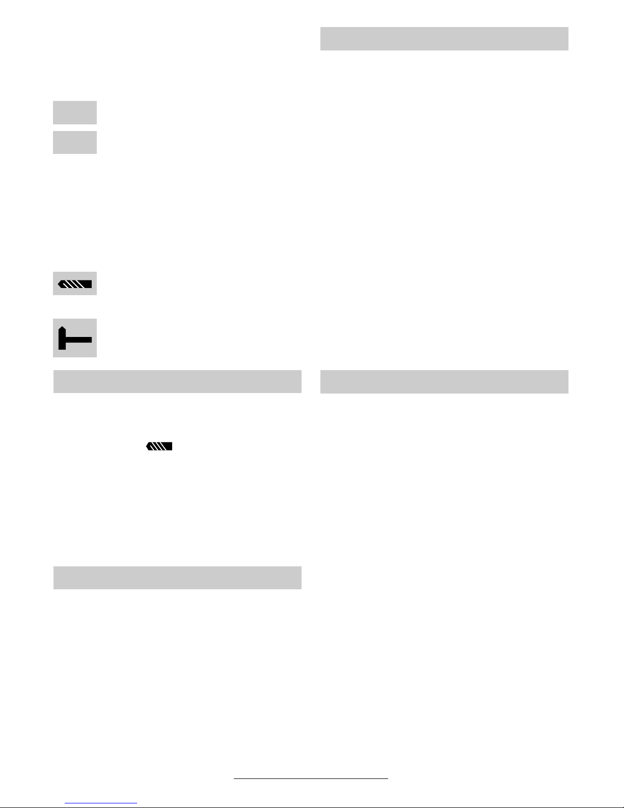
Drehmoment einstellen
Im praktischen Versuch ist zu ermitteln, mit welcher der 15 Einstellungen des Drehmoment-Einstellrings 3 die Schrauben bündig in das Material
eingedreht werden.
Schwache Einstellung, z. B. kleine
Schrauben, weiche Werkstoffe.
Starke Einstellung, z. B. große Schrauben, harte Werkstoffe.
Bei richtiger Einstellung öffnet die Überrastkupplung, sobald die Schraube bündig in das Material
eingedreht bzw. das eingestellte Drehmoment erreicht ist. Beim Herausdrehen höhere Einstellung
wählen, bzw. auf Symbol „Bohren“ stellen.
Bohren und Schlagbohren
Bohren
Den Drehmoment-Einstellring 3 auf das
Symbol „Bohren“ stellen.
Schlagbohren (GSB 18 VE-2/GSB 24 VE-2)
Den Drehmoment-Einstellring 3 auf das
Symbol „Hammerbohren“ stellen.
■ Vor allen Arbeiten am Gerät den Akku her-
ausnehmen.
Zum Wechseln des Bohrfutters, den Einstellring 3 in Position bringen.
Das Bohrfutter ist gegen das Lösen von der Bohrspindel mit der Sicherungsschraube gesichert.
Das Bohrfutter ganz öffnen und die Sicherungsschraube (Achtung Linksgewinde!) vollständig
herausschrauben.
Die Montage des Bohrfutters erfolgt in umgekehrter Reihenfolge.
Softgrip
Die rückseitig angebrachte Griff-Fläche 11 (Softgrip) erhöht die Abrutschsicherheit und sorgt dadurch für bessere Griffigkeit und Handlichkeit des
Gerätes.
Durch die Gummierung wird gleichzeitig eine vibrationshemmende Wirkung erzielt.
■ Verwenden Sie nur zum Schraubenkopf passende Schrauberklingen/Bits.
■ Bei Eindrehen größerer, längerer Schrauben
in harten Werkstoffen am besten vorbohren.
■ Beim Bohren in Metall nur einwandfreie geschärfte HSS-Bohrer (HSS = HochleistungsSchnell-Schnittstahl) verwenden. Entsprechende Qualität garantiert das Bosch-Zubehör-Programm.
Bohren von Fliesen
Um Fliesen zu bohren, den Drehmoment-Einstellring 3 auf das Symbol „Bohren“ stellen. Erst
nach Durchbohren der Fliese auf das Symbol
„Hammerbohren“ umschalten und mit Schlag arbeiten.
■ Vor allen Arbeiten am Gerät den Akku herausnehmen.
☞
Gerät und Lüftungsschlitze stets sauber
halten, um gut und sicher zu arbeiten.
Sollte das Gerät trotz sorgfältiger Herstellungsund Prüfverfahren einmal ausfallen, ist die Reparatur von einer autorisierten Kundendienststelle
für Bosch-Elektrowerkzeuge ausführen zu lassen.
Bei allen Rückfragen und Ersatzteilbestellungen
bitte unbedingt die 10-stellige Bestellnummer laut
Typenschild des Gerätes angeben.
Bohrfutter wechseln
Arbeitshinweise
1
15
Tipps
Wartung und Reinigung
7 • 2 609 932 048 • TMS • 16.01.03
Deutsch - 5
Rohstoffrückgewinnung statt Müllentsorgung
Gerät, Zubehör und Verpackung sollten einer
umweltgerechten Wiederverwertung zugeführt
werden.
Diese Anleitung ist aus chlorfrei gefertigtem Recycling-Papier hergestellt.
Zum sortenreinen Recycling sind Kunststoffteile
gekennzeichnet.
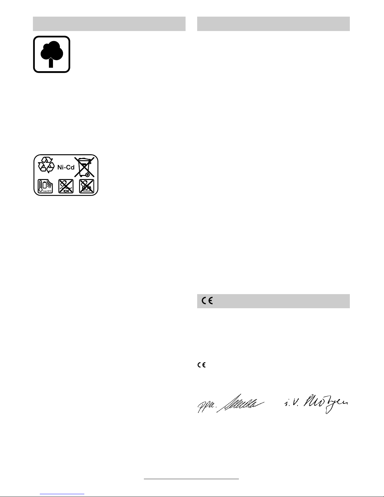
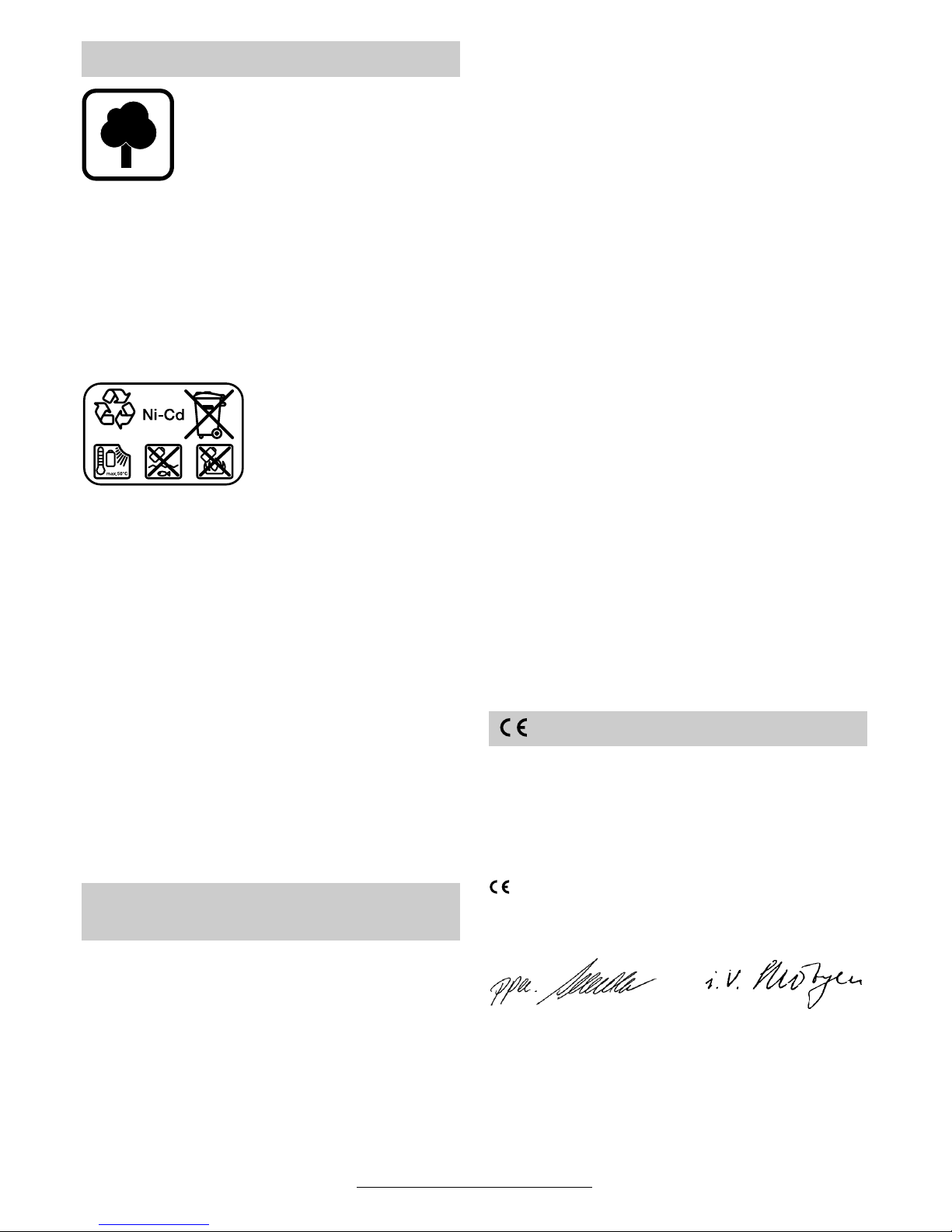
Nickel-Cadmium-Akku:
Wenn Ihr Produkt mit einem Nickel-CadmiumAkku ausgerüstet ist,
muss der Akku gesammelt, recycelt oder auf
umweltfreundliche Weise
entsorgt werden.
Defekte oder verbrauchte Akkus müssen gemäß
Richtlinie 91/157/EWG recycelt werden.
Nicht mehr gebrauchsfähige Akkus/Batterien
können direkt abgegeben werden bei:
Deutschland
Recyclingzentrum Elektrowerkzeuge
Osteroder Landstraße 3
37589 Kalefeld
Schweiz
Batrec AG
3752 Wimmis BE
In Deutschland sind nicht mehr gebrauchsfähige
Geräte zum Recycling beim Handel abzugeben
oder (ausreichend frankiert) direkt einzuschicken
an:
Recyclingzentrum Elektrowerkzeuge
Osteroder Landstraße 3
37589 Kalefeld
www.powertool-portal.de, das Internetportal
für Handwerker und Heimwerker
www.ewbc.de, der Informations-Pool für Handwerk und Ausbildung
Deutschland
Robert Bosch GmbH
Servicezentrum Elektrowerkzeuge
Zur Luhne 2
37589 Kalefeld
✆ Service: ....................................... 01 80 - 3 35 54 99
Fax
............................................. +49 (0) 55 53 / 20 22 37
✆ Kundenberater:...................... 01 80 - 3 33 57 99
Österreich
ABE Service GmbH
Jochen-Rindt-Straße 1
1232 Wien
✆ Service: ..................................... +43 (0)1 / 61 03 80
Fax
................................................. +43 (0)1 / 61 03 84 91
✆ Kundenberater:............. +43 (0)1 / 797 22 3066
E-Mail: abe@abe-service.co.at
Schweiz
✆ Service: ................................. +41 (0)1 / 8 47 16 16
✆ Kundenberater:...... Grüne Nr. 0 800 55 11 55
Wir erklären in alleiniger Verantwortung, dass dieses Produkt mit den folgenden Normen oder normativen Dokumenten übereinstimmt: EN 50 144
(Akku-Geräte) bzw. EN 60 335 (Akku-Ladegeräte) gemäß den Bestimmungen der Richtlinien
73/23/EWG, 89/336/EWG, 98/37/EG.
03
Dr. Egbert Schneider Dr. Eckerhard Strötgen
Senior Vice President Head of Product
Engineering Certification
Robert Bosch GmbH, Geschäftsbereich Elektrowerkzeuge
Änderungen vorbehalten
Umweltschutz Service und Kundenberater
Konformitätserklärung
8 • 2 609 932 048 • TMS • 16.01.03

English - 1
1 Gear selector
2 Auxiliary handle
3 Torque setting ring
4 Keyless chuck
5 Screw
6 Battery
7 Battery unlocking button
8 Screwdriver bit
9 On/Off switch
10 Rotational direction switch
11 Soft grip
Not all of the accessories illustrated or described are
included as standard delivery.
Measured values determined according to
EN 50 144.
GSR 18 VE-2/GSR 24 VE-2:
Typically the A-weighted sound pressure level of
the product is less than 70 dB (A).
The noise level when working can exceed
85 dB (A).
Wear hearing protection!
The typical hand/arm vibration is below 2.5 m/s
2
.
GSB 18 VE-2/GSB 24 VE-2:
Typically the A-weighted noise levels of the product are: sound pressure level: 89 dB (A); sound
power level: 102 dB (A).
Wear hearing protection!
The typically weighted acceleration is 7.5 m/s
2
.
Tool Specifications
Cordless screwdriver GSR 18 VE-2 GSR 24 VE-2
Order number 0 601 951 3.. 0 601 951 2..
Cordless impact drill and
screwdriver
GSB 18 VE-2 GSB 24 VE-2
Order number 0 601 952 3.. 0 601 952 2..
No-load speed
1st gear [rpm] 0–400 0 –510 0–520 0–450
2nd gear [rpm] 0 –1 400 0–1 800 0 –1 850 0–1 500
Torque adjustment range [Nm] 1–10 1–10 1–10 1–10
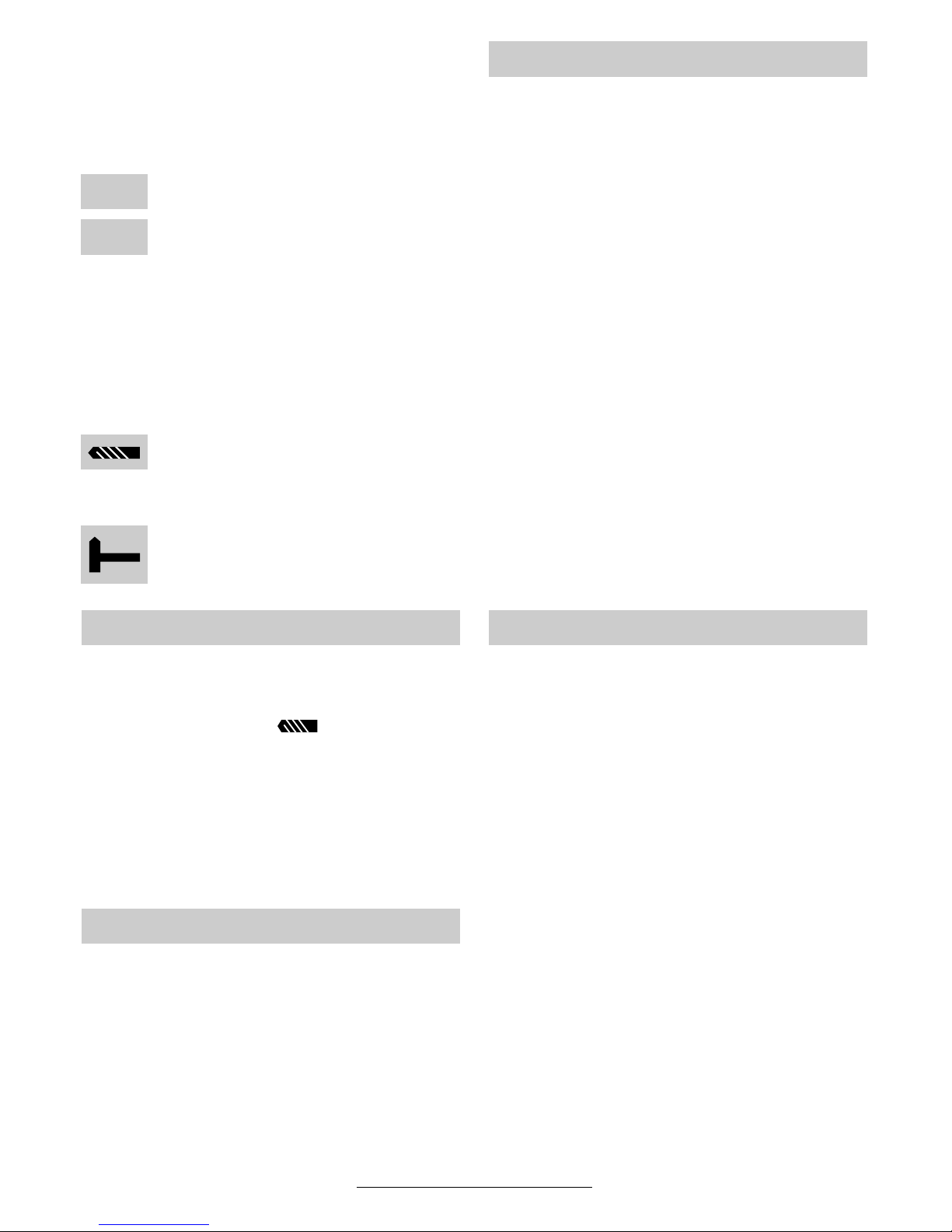
Torque, max. in
position “ ”:
Soft screwdriving case [Nm] 30 25 30 38
Hard screwdriving case [Nm] 55 50 55 65
Drilling dia., steel, max. [mm] 14 13 14 15
Drilling dia., wood, max. [mm] 36 35 36 38
Drilling dia., stone, max. [mm] – 16 17 –
Screw diameter, max. [mm] 10 10 12 14
Chuck clamping range [mm] 1.5–13 1.5 –13 1.5–13 1.5–13
Auto-Lock ● ● ● ●
Drill spindle thread 1/2" 1/2" 1/2" 1/2"
Weight (without accessories),
approx.
[kg] 2.5 2.7 3.1 2.8
Battery NiCd NiCd NiCd NiCd
Temperature control NTC NTC NTC NTC
Rated voltage [V=] 18 18 24 24
Capacity [Ah] 2.0 2.0 2.0 2.0
Weight, approx. [kg] 0.95 0.95 1.3 1.3
Please observe the order number of your machine. The trade names of the individual machines may vary.
Machine Elements Noise/Vibration Information
9 • 2 609 932 048 • TMS • 16.01.03

English - 2
Working safely with this machine is possible only when the
operating and safety information
are read completely and the instructions contained therein are
strictly followed. In addition, the
general safety notes in the enclosed booklet
must be observed.
■ Wear safety goggles.
■ For long hair, wear hair protection. Work only
with closely fitting clothes.
■ Before each use, check the machine and bat-
tery. If damage is detected, do not use the machine. Have repairs performed only by a qualified technician. Never open the machine yourself.
■ Before any work on the machine itself (e. g.
maintenance, tool change, etc.) as well as
when transporting and storing, always set
the rotational direction switch to the centre
position. Otherwise danger of injury is given
when unintentionally actuating the On/Off
switch.
■ Convince yourself before using that the battery
is securely seated in the machine.
■ Use appropriate detectors to determine if
utility lines are hidden in the work area or
call the local utility company for assistance.
Contact with electric lines can lead to fire and
electric shock. Damaging a gas line can lead
to explosion. Penetrating a water line causes
property damage.
■ Operate the machine only with the auxiliary
handle 2.
■ When working with the machine, always hold it
firmly with both hands and provide for a secure
stance.
■ Hold the machine tightly: When driving in
screws, high reaction moments can briefly occur.
■ Secure the workpiece. A workpiece clamped
with clamping devices or in a vice is held more
secure than by hand.
■ Never allow children to use the machine.
■ Bosch is only able to ensure perfect operation
of the machine if the original accessories intended for it are used.
Battery and Battery Charger
■ The enclosed operating instructions for the
battery charger must be read carefully!
■ Do not open the battery, and protect it from impact. Store in a dry and frost-free place.
■ Allow a heated battery to cool before charging.
■ Protect the battery from heat and fire: Danger
of explosion! Do not place the battery on radiators or expose to strong sun rays for a longer
time; temperatures over 50 °C cause damage.
■ Do not dispose of the battery in household
waste or discard into fire or water.
GSB: The machine is intended for screwing in
and loosening screws, for drilling in wood, metal,
ceramic and plastic and for impact drilling in brick,
concrete and stone.
GSR: The machine is intended for the screwing
in and loosening of screws as well as for drilling
in wood, metal, ceramic and plastic.
The auxiliary handle 2 provides additional safety,
as jolting reactions can occur during impact drilling, drilling large diameters and screwdriving.
Mount the auxiliary handle 2 on the right or left of
the power tool, depending on the working mode,
using screw 5.
Battery Charging
A battery that is new or has not been used for a
longer period does not develop its full capacity
until after approximately 5 charging / discharging
cycles.
To remove the battery 6, press the unlocking buttons 7 and pull out the battery downwards. Do not
exert any force.
The battery is equipped with an NTC temperature
control which allows charging only within a temperature range of between 0 °C and 45 °C.
A long battery service life is achieved in this manner.
A significantly reduced working period after
charging indicates that the batteries are used and
must be replaced.
■ Observe the notes on environmental protection.
For Your Safety
Intended Use
Auxiliary Handle
Before Putting into Operation
10 • 2 609 932 048 • TMS • 16.01.03
English - 3
Open the drill chuck until the tool can be inserted.
Insert the tool.
Firmly tighten the sleeve of the keyless chuck 4
by hand until the locking action (“click”) is no
longer heard. This automatically locks the chuck.
Rotate the sleeve in the reverse direction to remove the tool.
Screwdriving
Directly clamp the screwdriver bit 8 into the drill
chuck or use the additional universal bit holder
when operating with hex shank bits.
Inserting the Battery
Set the rotational direction switch 10 to the centre
position = lock-off and allow the charged battery 6 to engage into the handle.
Switching On and Off
To start the machine press the On/Off switch 9.
The machine runs with variable
speed between 0 and maximum,
depending on the pressure applied
to the On / Off switch 9. Light pres-
sure results in a low rotational
speed thus allowing smooth, controlled starts. Do not strain the machine so heavily that it comes to a
standstill.
To switch off the machine, release the On / Off
switch 9 .
Electric Brake
When releasing the On/Off switch 9 the speed of
the drill chuck is reduced to a stop, thus preventing the run-on of the tool.
For screwdriving applications, wait until the screw
is flush with the material and then release the On/
Off switch 9. The screw head does not penetrate
into the material then.
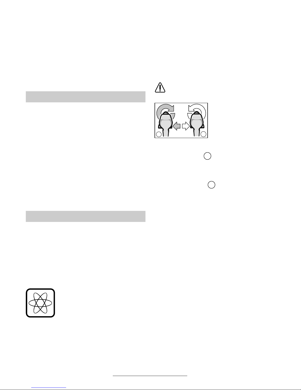
Reversing the Rotational Direction
Operate the rotational direction
switch 10 only at a standstill.
The rotational direction
switch 10 is used to re-
verse the rotational direction of the machine. However, this is not possible
with the On/Off switch 9
actuated.
Right Rotation ( )
Turn the rotational direction switch through to the
left stop (normal operation: drilling, screwdriving,
etc.).
Left Rotation ( )
Press the rotational direction switch through to
the right stop (for loosening and unscrewing
screws and nuts).
Gear Selection, Mechanical
Two speed ranges can be preselected with the
gear selector 1:
1st gear: Low rotational speed, high power.
2nd gear: High rotational speed, less power.
The speed settings may only be changed when
the machine is motionless. If the speed setting
has not quite notched in properly, briefly press
the On/Off switch 9.
Fully Automatic Spindle Locking
(Auto-Lock)
The drill spindle is locked when the On/Off
switch 9 is not pressed.
This makes quick and easy changing of the tool
in the drill chuck possible.
The locked drill chuck enables retightening of
projecting screws by using the switched-off machine as a screwdriver.
Note: Tightening by hand with too much force
can damage the screw.
Changing the Tool
Initial Operation
b
a
a
b
11 • 2 609 932 048 • TMS • 16.01.03

English - 4
Setting the Torque
Carry out a practical test to determine with which
of the 15 settings of the torque setting ring 3 the
screws are driven flush into the material.
Low setting, e. g., small screws, soft
materials.
High setting, e. g., large screws, hard
materials.
With the correct setting, the clutch disengages as
soon as the screw is driven flush into the material
or the set torque is reached. Select a higher setting when driving out screws, or set to the “Drilling” symbol.
Drilling and Impact Drilling
Drilling
Set the torque setting ring 3 to the “Drilling” symbol.
Hammer Drilling (GSB 18 VE-2/GSB 24 VE-2)
Set the torque setting ring 3 to the
“Hammer Drilling” symbol.
■ Before any work on the machine itself, re-
move the battery.
To change the chuck, place the setting ring 3 in
the position.
The locking screw secures the drill chuck against
loosening from the drill spindle. Fully open the
chuck and completely unscrew the locking screw
(Note: left-handed thread!).
The drill chuck is mounted in reverse order.
Soft grip
The gripping surface 11 on the rear of the handle
(soft grip) reduces the danger of slipping and
thereby improves the grip on the machine and the
handling.
At the same time, the rubber coating achieves a
vibration-reducing effect.
■ Use only screwdriver bits that fit properly in the
head of the screw.
■ When driving in larger and/or longer screws in
hard material, it is advisable to drill a pilot hole
first.
■ For drilling in metal, use only perfectly sharpened HSS drills. The appropriate quality is
guaranteed by the Bosch accessories program.
Drilling Tiles
When drilling through tiles, set the torque setting
ring 3 to the “Drilling” symbol. After drilling
through the tile, switch back to the “Hammer Drilling” symbol and continue working in hammer
mode.
■ Before any work on the machine itself, remove the battery.
☞
For safe and proper working, always keep
the machine and the ventilation slots clean.
If the machine should fail despite the care taken
in manufacturing and testing procedures, repair
should be carried out by an after-sales service
centre for Bosch power tools.
In all correspondence and spare parts orders,
please always include the 10-digit order number
given on the nameplate of the machine.
Replacing the Drill Chuck
Operating Instructions
1
15
Tips
Maintenance and Cleaning
12 • 2 609 932 048 • TMS • 16.01.03
English - 5
Recycle raw materials instead of disposing as
waste
The machine, accessories and packaging should
be sorted for environmental-friendly recycling.
These instructions are printed on recycled paper
manufactured without chlorine.
The plastic components are labelled for categorized recycling.
Nickel-cadmium-battery: If your product is
equipped with a nickelcadmium-battery, the battery must be collected, recycled or disposed of in an
environmentally-friendly
way.
Defective or worn out batteries must be recycled
according to the guidelines 91/157/EEC.
Batteries no longer suitable for use can be
directly returned at:
Great Britain
Robert Bosch Ltd. (B.S.C.)
P.O. Box 98
Broadwater Park
North Orbital Road
Denham-Uxbridge
Middlesex UB 9 5HJ
✆ Service............................ +44 (0)18 95 / 83 87 82
✆ Advice line .................... +44 (0) 18 95 / 83 87 91
Fax
............................................. +44 (0)18 95 / 83 87 89
Ireland
Beaver Distribution Ltd.
Greenhills Road
Tallaght-Dublin 24
✆ Service................................... +353 (0)1 / 414 9400
Fax
.................................................... +353 (0)1 / 459 8030
Australia
Robert Bosch Australia Ltd.
RBAU/SPT2
1555 Centre Road
P.O. Box 66 Clayton
3168 Clayton/Victoria
✆ ................................................ +61 (0)1 / 800 804 777
Fax
................................................ +61 (0)1 / 800 819 520
www.bosch.com.au
E-Mail: CustomerSupportSPT@au.bosch.com
New Zealand
Robert Bosch Limited
14-16 Constellation Drive
Mairangi Bay
Auckland
New Zealand
✆ ..................................................... +64 (0)9 / 47 86 158
Fax
..................................................... +64 (0)9 / 47 82 914
We declare under our sole responsibility that this
product is in conformity with the following standards or standardization documents. EN 50 144
(Battery powered products) and EN 60 335 (Battery charger) according to the provisions of the directives 73/23/EEC, 89/336/EEC, 98/37/EC.
03
Dr. Egbert Schneider Dr. Eckerhard Strötgen
Senior Vice President Head of Product
Engineering Certification
Robert Bosch GmbH, Geschäftsbereich Elektrowerkzeuge
Subject to change without notice
Environmental Protection
Service and Customer
Assistance
Declaration of Conformity
13 • 2 609 932 048 • TMS • 16.01.03

Français - 1
1 Commutateur de vitesse
2 Poignée supplémentaire
3 Bague de réglage du couple
4 Mandrin à serrage rapide
5 Vis
6 Accumulateur
7 Touche de déverrouillage de l’accumulateur
8 Lame de tournevis
9 Interrupteur Marche/Arrêt
10 Commutateur du sens de rotation
11 Point d’appui souple (antidérapant)
Les accessoires reproduits ou décrits ne sont pas
forcément fournis avec la machine.
Valeurs de mesure obtenues conformément à la
norme européenne 50 144.
GSR 18 VE-2/GSR 24 VE-2 :
La mesure réelle (A) du niveau sonore de l’outil
est inférieure à 70 dB (A).
Le niveau sonore en fonctionnement peut dépasser 85 dB (A).
Munissez-vous d’une protection acoustique!
La vibration de l’avant-bras est en-dessous de
2,5 m/s
2
.
GSB 18 VE-2/GSB 24 VE-2 :
Les mesures réelles (A) des niveaux sonores de
la machine sont : intensité de bruit 89 dB (A).
Niveau de bruit 102 dB (A).
Munissez-vous d’une protection acoustique !
L’accélération réelle mesurée est de 7,5 m/s
2
.
Caractéristiques techniques
Perceuse-visseuse sans fil GSR 18 VE-2 GSR 24 VE-2
Référence 0 601 951 3.. 0 601 951 2..
Visseuse-perceuse à
percussion sans fil
GSB 18 VE-2 GSB 24 VE-2
Référence 0 601 952 3.. 0 601 952 2..
Régime à vide
1ère vitesse [tr/min] 0–400 0 –510 0–520 0 –450
2ème vitesse [tr/min] 0–1 400 0–1 800 0 –1 850 0–1 500
Plage de réglage du couple [Nm] 1–10 1–10 1–10 1–10
Couple maximum sur la
position « »:
Vissages faciles [Nm] 30 25 30 38
Vissages difficiles [Nm] 55 50 55 65
Ø perçage dans l’acier, max. [mm] 14 13 14 15
Ø perçage dans le bois, max. [mm] 36 35 36 38
Ø perçage dans la pierre, max. [mm] – 16 17 –
Ø des vis, max. [mm] 10 10 12 14
Fixation du mandrin de
perçage
[mm] 1,5–13 1,5–13 1,5–13 1,5–13
Auto-Lock ● ● ● ●
Fixation de la broche 1/2" 1/2" 1/2" 1/2"
Poids (sans accessoires), env. [kg] 2,5 2,7 3,1 2,8
Accumulateur NiCd NiCd NiCd NiCd
Contrôle de température NTC NTC NTC NTC
Tension nominale [V=] 18 18 24 24
Capacité [Ah] 2,0 2,0 2,0 2,0
Poids, env. [kg] 0,95 0,95 1,3 1,3
Faire attention au numéro de référence de la machine. Les désignations commerciales des différentes machines peuvent
varier.
Eléments de la machine Bruits et vibrations
14 • 2 609 932 048 • TMS • 16.01.03

Français - 2
Pour travailler sans risque avec
cet appareil, lire intégralement
au préalable les instructions
d’utilisation et les remarques
concernant la sécurité. Respec-
ter scrupuleusement les indications et les consignes qui y sont données.
Respecter en plus les indications générales
de sécurité se trouvant dans le cahier ci-joint.
■ Porter des lunettes de protection.
■ Les personnes portant les cheveux longs doi-
vent se munir d’un protège-cheveux. Ne travailler qu’avec des vêtements près du corps.
■ Avant chaque utilisation, vérifier l’appareil et
l’accumulateur. Ne jamais mettre en marche
un appareil endommagé. Les réparations ne
doivent être confiées qu’à un spécialiste. Ne
jamais ouvrir l’appareil soi-même.
■ Avant d’effectuer des travaux sur l’appareil
(p. ex. travaux d’entretien, changement
d’outils, etc.) et avant de le transporter ou
stocker, toujours mettre le commutateur de
sens de rotation en position médiane. Si-
non, il y a risque de blessure lorsqu’on appuie
par mégarde sur l’interrupteur Marche/Arrêt.
■ Avant utilisation, toujours contrôler que l’accu-
mulateur est correctement en place.
■ Utiliser des détecteurs appropriés afin de
déceler des conduites cachées ou consulter les entreprises d’approvisionnement locales.
Un contact avec des conduites d’électricité
peut provoquer un incendie ou un choc électrique. L’endommagement d’une conduite de
gaz peut provoquer une explosion. La perforation d’une conduite d’eau provoque des dégâts
matériels.
■ N’utilisez votre appareil qu’avec la poignée
supplémentaire 2.
■ Pendant le travail avec cet appareil, le tenir
toujours fermement avec les deux mains.
Adopter une position stable et sûre.
■ Bien tenir la machine : Lors du vissage, il peut
y avoir des couples de réaction élevés.
■ Bloquer la pièce à travailler. Une pièce à tra-
vailler serrée par des dispositifs de serrage ou
dans un étau est fixée de manière plus sûre
que si elle est seulement tenue de la main.
■ Ne jamais permettre aux enfants d’utiliser cet
appareil.
■ Bosch ne peut garantir un fonctionnement im-
peccable que si les accessoires Bosch d’origine prévus pour cet appareil sont utilisés.
Accumulateur et chargeur
■ Lire absolument le mode d’emploi du char-
geur ci-joint !
■ Ne pas ouvrir l’accumulateur. Le protéger de
tout choc mécanique. L’entreposer dans un
endroit sec et à l’abri du gel.
■ Avant de recharger un accumulateur échauffé,
le laisser refroidir.
■ Protéger l’accumulateur contre toute exposition à la chaleur ou au feu : risque d’explosion ! Ne pas poser l’accumulateur sur un
corps chaud (radiateur, par exemple). Ne pas
l’exposer trop longtemps à un fort ensoleillement. Les températures dépassant 50 °C lui
sont néfastes.
■ Ne pas jeter l’accu dans les ordures ménagères, ni dans les flammes ou dans l’eau.
GSB : L’appareil est conçu pour le vissage et dévissage des vis, pour le perçage dans le bois, le
métal, la céramique et les matières plastiques
ainsi que pour le perçage à percussion dans la
brique, le béton et dans la roche.
GSR : L’appareil est conçu pour le vissage et le
dévissage des vis ainsi que pour le perçage dans
le bois, le métal, le céramique et les matières
plastiques.
La poignée supplémentaire 2 vous offre davan-
tage de sécurité, étant donné que lors du perçage en frappe, du perçage de grands diamètres
et lors du vissage, il peut y avoir de fortes réactions au niveau de l’appareil.
En fonction du mode de travail, visser la poignée
supplémentaire 2 du côté droit ou du côté gauche
de l’appareil au moyen de la vis 5.
Recharge de l’accumulateur
Un accu neuf ou un accu qui n’a pas été utilisé
pendant une période assez longue, n’atteint sa
pleine puissance qu’après environ cinq cycles de
charge et de décharge.
Pour sortir l’accumulateur 6, appuyer sur les boutons de déverrouillage 7 et retirer l’accumulateur
vers le bas. Ne pas forcer.
Pour votre sécurité
Utilisation conformément à la
destination de l’appareil
Poignée supplémentaire
Avant la mise en service
15 • 2 609 932 048 • TMS • 16.01.03
Français - 3
L’accumulateur est doté d’un dispositif de surveillance de la température NTC ne permettant la
charge que dans une plage de température comprise entre 0 °C et 45 °C. La longévité de l’accumulateur s’en trouve ainsi accrue.
Si le temps de service des accus se raccourcit
considérablement après un processus de
charge, cela indique que les accus sont usés et
qu’ils doivent être remplacés.
■ Observer les consignes relatives à la protection de l’environnement.
Ouvrir le mandrin de perçage de sorte que l’outil
puisse être monté. Monter l’outil.
Visser fermement la douille du mandrin à serrage
rapide 4 à la main, jusqu’à ce qu’aucun bruit correspondant au passage d’un cran ne soit plus
audible (« cliquetis »). Ceci permet le verrouillage automatique du mandrin porte-foret.
Tourner le corps dans le sens inverse pour retirer
l'outil.
Vissage
Serrer les lames de tournevis 8 directement dans
le mandrin de perçage ou en cas d’utilisation
d’embouts tournevis (bits), utiliser en plus un
porte-embout universel.
Mise en place de l’accumulateur
Mettre le commutateur du sens de rotation 10
dans la position médiane = verrouillage de mise
en fonctionnement et faire encliqueter l’accu
chargé 6 dans la poignée.
Mise en fonctionnement/Arrêt
Afin de mettre l’appareil en fonctionnement,
appuyer sur l’interrupteur Marche/Arrêt 9.
En fonction de la pression exercée
sur l’interrupteur Marche/Arrêt 9,
l’appareil fonctionne à une vitesse
comprise entre 0 et le maximum.
Une légère pression fait tourner
l’appareil à petite vitesse, ce qui
permet un démarrage précis et en
douceur. Ne pas trop solliciter l’appareil qui risque sinon de s’arrêter.
Afin d’arrêter l’appareil, relâcher l’interrupteur
Marche/Arrêt 9.
Frein de ralentissement
Lorsqu’on relâche l’interrupteur Marche /Arrêt 9,
le mandrin est freiné, ce qui évite un fonctionnement par inertie de l’outil.
Lors de travaux de vissage, ne relâcher l’interrupteur Marche/Arrêt 9 que lorsque la vis est enfoncée à ras dans le matériau. La tête de vis ne pénètre alors pas le matériau.
Inversion du sens de rotation
N’actionner le commutateur du sens de
rotation 10 qu’à l’arrêt total de l’appareil.
Le sens de rotation de
l’appareil peut être modifié à l’aide du commutateur du sens de rotation 10. Cela n’est toute-
fois pas possible en
actionnant l’interrupteur
Marche/Arrêt 9.
Rotation à droite ( )
Pousser à fond le commutateur du sens de rotation vers la gauche (service normal : perçage,
vissage, etc.).
Rotation à gauche ( )
Repousser à fond le commutateur du sens de rotation vers la droite « Rotation à droite » (pour les
travaux de desserrage, de dévissage de vis et
d’écrous).
Commutation mécanique de la vitesse
Le commutateur de vitesse 1 permet de sélec-
tionner deux plages de vitesse de rotation :
1ère vitesse : Petite vitesse, force élevée.
2ème vitesse : Vitesse élevée, force faible.
On ne peut changer de vitesse que lorsque la
machine est à l'arrêt. Si la vitesse ne s'enclenche
pas complètement, appuyer un court instant sur
l'interrupteur Marche/Arrêt 9.
Blocage de broche automatique
(Auto-Lock)
Lorsque l’interrupteur Marche/Arrêt 9 n’est pas
appuyé, la broche de perçage est bloquée.
Ceci permet de remplacer l’outil utilisé dans le
mandrin de manière rapide, aisée et facile.
Le blocage du mandrin permet de resserrer les
vis en saillie, en utilisant la machine à l’arrêt
comme d’un tournevis.
Remarque : Un serrage manuel trop important
peut endommager la vis.
Changement de l’outil
Mise en service
b
a
a
b
16 • 2 609 932 048 • TMS • 16.01.03
Français - 4
Réglage du couple
En effectuant des essais pratiques, déterminer le
réglage approprié parmi les 15 positions possibles de la bague de réglage du couple 3 afin de
pouvoir visser correctement les vis afin que leur
tête affleure le matériau.
Couple réduit p. ex. petites vis, matériaux tendres.
Couple élevé p. ex. grandes vis, matériaux durs.
Le réglage est correct lorsque l’embrayage à
crans est déclenché dès que la tête de la vis affleure le matériau ou que le couple préréglé est
atteint. Pour dévisser, choisir un réglage plus
élevé, ou régler sur le symbole « Perçage ».
Perçage et perçage à percussion
Perçage
Positionner la bague de réglage du couple 3 sur le symbole « Perçage ».
Perçage en frappe
(GSB 18 VE-2/GSB 24 VE-2)
Positionner la bague de réglage du couple 3 sur le symbole « Perçage en
frappe ».
■ Avant toute intervention sur l’appareil proprement dit, retirer l’accumulateur.
Pour changer le mandrin, amener la bague de réglage 3 dans la position .
Pour ne pas se déloger de l’unité de perçage, le
mandrin est équipé d’une vis de retenue. Ouvrir
complètement le mandrin et dévisser totalement
la vis de retenue (Attention, filetage à gau-
che !).
Pour monter le mandrin, procéder en sens inverse.
Softgrip
La surface arrière de la poignée 11 évite un glissement de la main et permet ainsi une meilleure
maniabilité de l'appareil.
Grâce au revêtement en caoutchouc, les vibrations sont également atténuées.
■ N’utiliser que des lames de tournevis et des
embouts de vissage adaptés à la tête de la vis.
■ Lors du vissage de vis de taille et de longueur
importantes dans des matériaux durs, il est recommandé de percer un avant-trou.
■ Lors de perçage dans les métaux, n’utiliser
que des forets HSS en bon état et bien affûtés
(HSS = aciers super rapides). Le programme
d’accessoires Bosch garantit la qualité des forets.
Perçage dans carrelage
Pour percer dans les carreaux de faïence, positionner la bague de réglage du couple 3 sur le
symbole « Perçage ». Une fois le carreau de
faïence percé, positionner le commutateur sur le
symbole « Perçage en frappe » et continuer le
travail en mode de perçage en frappe.
■ Avant toute intervention sur l’appareil proprement dit, retirer l’accumulateur.
☞
Pour obtenir un travail sûr et satisfaisant,
nettoyer régulièrement l’appareil ainsi que
ses ouïes de refroidissement.
Si, malgré tous les soins apportés à la fabrication
et au contrôle de l’appareil, celui-ci devait avoir
un défaut, la réparation ne doit être confiée qu’à
une station de service après-vente agréée pour
outillage Bosch.
Pour toute demande de renseignements ou commande de pièces de rechange, nous préciser impérativement le numéro de référence à dix chiffres de la machine.
Changement du mandrin
Instructions d’utilisation
1
15
Conseils d’utilisation
Nettoyage et entretien
17 • 2 609 932 048 • TMS • 16.01.03
Français - 5
Récupération des matières premières plutôt
qu’élimination des déchets
Les machines, comme d’ailleurs leurs accessoires et emballages, doivent pouvoir suivre chacune une voie de recyclage appropriée.
Ce manuel d’instructions a été fabriqué à partir
d’un papier recyclé blanchi sans chlore.
Nos pièces plastiques ont ainsi été marquées en
vue d’un recyclage sélectif des différents matériaux.
Accumulateur NickelCadmium : Au cas où vo-
tre produit serait équipé
d’un accu Nickel-Cadmium, l’accu doit être récupéré, recyclé ou éliminé
en conformité avec les réglementations se rapportant à l’environnement.
Les accus usés ou défectueux doivent être recyclés conformément à la directive 91/157/CEE.
Les accus /piles dont on ne peut plus se servir
peuvent être déposés directement auprès de :
Suisse
Batrec AG
3752 Wimmis BE
France
Information par Minitel 11
Nom : Bosch Outillage
Loc : Saint Ouen
Dépt : 93
Robert Bosch France S.A.
Service Après-vente/Outillage
B.P. 67-50, Rue Ardoin
93402 St. Ouen Cedex
✆ Service conseil client,
Numéro Vert
.................................... 0 800 05 50 51
Belgique
Robert Bosch S.A.
After Sales Service Outillage
Rue Henri Genesse 1
1070 Bruxelles
✆ ..................................................... +32 (0)2 / 525.50.29
Fax
..................................................... +32 (0)2 / 525.54.30
✆ Service conseil client..... +32 (0)2 / 525.53.07
E-Mail : Outillage.Gereedschappen@be.bosch.com
Suisse
✆ .................................................... +41 (0)1 / 8 47 16 16
✆ Service conseil client,
Numéro Vert
.................................... 0 800 55 11 55
Nous déclarons sous notre propre responsabilité
que ce produit est en conformité avec les normes
ou documents normalisés : EN 50 144 (appareils
sans fil) respectivement EN 60 335 (chargeurs
électriques) conformément aux termes des réglementations 73/23/CEE, 89/336/CEE, 98/37/CE.
03
Dr. Egbert Schneider Dr. Eckerhard Strötgen
Senior Vice President Head of Product
Engineering Certification
Robert Bosch GmbH, Geschäftsbereich Elektrowerkzeuge
Sous réserve de modifications
Instructions de protection de
l’environnement
Service Après-Vente
Déclaration de conformité
18 • 2 609 932 048 • TMS • 16.01.03

Español - 1
1 Selector de velocidades
2 Empuñadura adicional
3 Anillo de ajuste de par
4 Portabrocas de sujeción rápida
5 Tornillo
6 Acumulador
7 Tecla de desenclavamiento del acumulador
8 Punta de atornillar
9 Interruptor de conexión/desconexión
10 Selector de sentido de giro
11 Softgrip
Los accesorios descritos e ilustrados no corresponden
en parte al material que se adjunta de serie.
Determinación de los valores de medición según
norma EN 50 144.
GSR 18 VE-2/GSR 24 VE-2:
El nivel de presión de sonido, típico, medido con
un filtro tipo A, es normalmente menor de
70 dB (A).
El nivel de ruido, con la máquina trabajando, podrá sobrepasar circunstancialmente 85 dB (A).
¡Usar protectores auditivos!
El nivel de vibraciones típico en la mano/brazo es
menor de 2,5 m/s
2
.
GSB 18 VE-2/GSB 24 VE-2:
El nivel de ruido típico del aparato corresponde a:
nivel de presión de sonido 89 dB (A); nivel de potencia de sonido 102 dB (A).
¡Usar protectores auditivos!
El nivel de vibraciones típico es de 7,5 m/s
2
.
Características técnicas
Atornilladora taladradora
accionada por acumulador
GSR 18 VE-2 GSR 24 VE-2
Número de pedido 0 601 951 3.. 0 601 951 2..
Atornilladora-taladradora de
percusión con acumulador
GSB 18 VE-2 GSB 24 VE-2
Número de pedido 0 601 952 3.. 0 601 952 2..
Revoluciones en vacío
1ª velocidad [min-1] 0–400 0–510 0 –520 0–450
2ª velocidad [min-1] 0–1 400 0–1 800 0 –1 850 0–1 500
Ajuste del par de giro [Nm] 1–10 1–10 1–10 1–10
Par de giro máx. en
posición “ ”:
Unión blanda [Nm] 30 25 30 38
Unión rígida [Nm] 55 50 55 65
Ø de taladro en acero, máx. [mm] 14 13 14 15
Ø de taladro en madera, máx. [mm] 36 35 36 38
Ø de taladro en piedra, máx. [mm] – 16 17 –
Ø de tornillo, máx. [mm] 10 10 12 14
Capacidad de sujeción del
portabrocas
[mm] 1,5–13 1,5–13 1,5–13 1,5–13
Auto-Lock ● ● ● ●
Rosca del husillo de taladrar 1/2" 1/2" 1/2" 1/2"
Peso (sin accesorios), aprox. [kg] 2,5 2,7 3,1 2,8
Acumulador NiCd NiCd NiCd NiCd
Control de temperatura NTC NTC NTC NTC
Tensión nominal [V=] 18 18 24 24
Capacidad [Ah] 2,0 2,0 2,0 2,0
Peso, aprox. [kg] 0,95 0,95 1,3 1,3
Preste atención al nº de pedido de su máquina. Las denominaciones comerciales en ciertas máquinas pueden variar.
Elementos del aparato Información sobre ruidos y
vibraciones
19 • 2 609 932 048 • TMS • 16.01.03

Español - 2
Solamente puede trabajar sin peligro con el aparato si lee íntegramente las instrucciones de
manejo y las indicaciones de seguridad, ateniéndose estricta-
mente a las recomendaciones
allí comprendidas. Adicionalmente deberán
respetarse las instrucciones de seguridad generales comprendidas en el folleto adjunto.
■ Ponerse unas gafas de protección.
■ Si tiene el pelo largo, recójaselo bajo una pro-
tección adecuada. Trabajar únicamente con
vestimenta ceñida al cuerpo.
■ Antes de cada utilización controlar el aparato
y el acumulador. En caso de detectar algun
daño, no continuar usando el aparato. Hacerlo
reparar solamente por personal técnico especializado. No abrir jamás el aparato por su propia cuenta.
■ Siempre colocar en posición central el se-
lector del sentido de giro antes de cualquier manipulación en el aparato (p. ej.
mantenimiento, cambio de útil, etc.) así
como al transportarlo y guardarlo. En caso
contrario existe el riesgo de lesión al accionar
accidentalmente el interruptor de conexión/
desconexión.
■ Asegúrese antes de su utilización que el acu-
mulador esté firmemente sujeto en el aparato.
■ Utilice unos instrumentos de exploración
adecuados para detectar tuberías y cables
ocultos, o consulte a su compañía abastecedora local.
El contacto con cables eléctricos puede provocar un incendio o sacudida eléctrica. El deterioro de tuberías de gas puede producir una
explosión. La perforación de una tubería de
agua puede causar daños materiales.
■ Solamente emplee el aparato con la empuña-
dura adicional 2.
■ Trabajar siempre con el aparato sujetándolo
firmemente con ambas manos y manteniendo
una posición estable.
■ Sujetar el aparato firmemente: al trabajar pue-
den presentarse brevemente unos pares de
reacción elevados.
■ Asegure la pieza de trabajo. Una pieza de
trabajo fijada con unos dispositivos de sujeción, o en un tornillo de banco, se mantiene
sujeta de forma mucho más segura que con la
mano.
■ Jamás permita que los niños utilicen el apa-
rato.
■ Bosch solamente puede garantizar el funcionamiento correcto del aparato si se utilizan los
accesorios originales previstos.
Acumulador y cargador
■ ¡Es imprescindible leer las instrucciones
de manejo del cargador que se adjuntan!
■ No abrir el acumulador, y protegerlo contra
golpes. Guardarlo en un lugar seco y libre de
heladas.
■ Dejar enfriar un acumulador caliente antes de
cargarlo.
■ Proteger el acumulador del calor y del fuego:
¡Peligro de explosión! No depositar el acumulador sobre radiadores ni exponerlo durante
tiempo prolongado al sol; las temperaturas por
encima de los 50 °C pueden dañarlo.
■ No tirar el acumulador a la basura, fuego o
agua.
GSB: El aparato ha sido proyectado para enroscar y aflojar tornillos, para taladrar madera, metal, cerámica y material sintético, y para taladrar
con percusión ladrillo, hormigón y piedra.
GSR: El aparato ha sido proyectado para enroscar y aflojar tornillos, así como para taladrar en
madera, metal, cerámica y materiales sintéticos.
La empuñadura adicional 2 ofrece una mayor seguridad, ya que al taladrar con percusión, al realizar perforaciones de gran diámetro y al atornillar
tornillos grandes, pueden presentarse unos pares de reacción bruscos.
Dependiendo de la aplicación, montar la empuñadura adicional 2 a la derecha o izquierda del
aparato con el tornillo 5.
Carga del acumulador
Un acumulador nuevo o que no haya sido usado
durante largo tiempo alcanza su plena potencia
después de aprox. 5 ciclos de carga y descarga.
Para desmontar el acumulador 6 presionar las
teclas de desenclavamiento 7 y sacarlo, tirando
de él hacia abajo sin brusquedad.
Para su seguridad
Utilización reglamentaria
Empuñadura adicional
Antes de la puesta en
funcionamiento
20 • 2 609 932 048 • TMS • 16.01.03
Español - 3
El acumulador está equipado con un sensor de
temperatura NTC que solamente permite la
carga a temperaturas entre 0 °C y 45 °C. Con
esto se consigue una larga duración del acumulador.
Si después de cargar los acumuladores el tiempo
de funcionamiento fuese muy reducido, ello es
señal de que están agotados y deben sustituirse.
■ Ténganse en cuenta las instrucciones para
protección del medio ambiente.
Abrir el portabrocas lo suficiente para poder insertar el útil. Introducir el útil.
Apretar firmemente a mano el casquillo del portabrocas de sujeción rápida 4 hasta dejar de percibir el ruido de carraca (“clic”). De esta manera
se enclava automáticamente el portabrocas.
Girar el casquillo en dirección contraria para retirar el útil.
Atornillado
Sujetar la punta de atornillar 8 directamente en el
portabrocas, o en caso de utilizar láminas de
destornillador (bits), emplear adicionalmente un
portaláminas universal.
Montaje del acumulador
Colocar el selector de sentido de giro 10 en la posición del centro = bloqueador de conexión, e insertar en la empuñadura, hasta que enclave, el
acumulador cargado 6.
Conexión y desconexión
Para la puesta en marcha del aparato presionar
el interruptor de conexión/desconexión 9.
La máquina funciona con un número de revoluciones variable entre 0 y máximo según la presión
ejercida sobre el interruptor de
conexión/desconexión 9. Presio-
nándolo ligeramente, se consigue
un régimen de giro reducido, lo que
permite una puesta en marcha
suave y controlada. No solicitar el
aparato de manera que llegue a detenerse.
Para desconectar el aparato soltar el interruptor
de conexión/desconexión 9.
Freno de marcha por inercia
Al soltar el interruptor de conexión/desconexión 9 se frena el portaútiles, impidiéndose así
que la herramienta siga girando por inercia.
Al atornillar, no soltar el interruptor de conexión/
desconexión 9 hasta que el tornillo haya quedado enrasado con el material. La cabeza del tornillo no penetra entonces en el material.
Conmutación del sentido de giro
Accionar el selector de sentido de giro 10
solamente con el aparato detenido.
El selector de sentido de
giro 10 sirve para invertir
el sentido de giro de la
máquina. Ello no es posible, sin embargo, si se
mantiene presionado el
interruptor de conexión/
desconexión 9.
Dirección de giro a derechas ( )
Girar a la izquierda hasta el tope el selector de
sentido de giro (modo de operación normal: taladrar, atornillar, etc.).
Dirección de giro a izquierdas ( )
Presionar a tope hacia la derecha el selector de
sentido de giro (para aflojar o desenroscar tornillos y tuercas).
Selector mecánico de velocidad
Con el selector de velocidades 1 pueden ajus-
tarse dos márgenes de velocidad:
1
ª
velocidad: Velocidad de giro baja,
par elevado.
2
ª
velocidad: Velocidad de giro elevada,
par bajo.
Las velocidades deben conectarse únicamente
con la máquina detenida. Si la velocidad entrase
con dificultad, presionar brevemente el interruptor de conexión/desconexión 9.
Enclavamiento automático del husillo
(Auto-Lock)
El husillo de taladrar se mantiene enclavado al
no accionar el interruptor de conexión/desconexión 9.
Ello permite cambiar el útil montado en el portabrocas de forma sencilla, cómoda y rápida.
El portabrocas enclavado al estar desconectada
la máquina permite emplear ésta como destornillador para reapretar aquellos tornillos que sobresalgan del material.
Observación: Un reapriete excesivo puede llegar a dañar el tornillo.
Cambio de útil
Puesta en servicio
b
a
a
b
21 • 2 609 932 048 • TMS • 16.01.03
 Loading...