


IMPORTANT: IMPORTANT : IMPORTANTE:
Read Before Using Lire avant usage Leer antes de usar
Operating/Safety Instructions
Consignes de fonctionnement/sécurité
Instrucciones de funcionamiento y seguridad
GCL100-80C
GCL100-80CG
Call Toll Free
for Consumer
Information &
Service Locations
Pour obtenir des informations
et les adresses de nos centres
de service après-vente,
appelez ce numéro gratuit
Llame gratis para
obtener información
para el consumidor y
ubicaciones de servicio
For English Version
See page 8
Find Quality Products Online at: sales@GlobalTestSupply.com
www.GlobalTestSupply.com

14
13
1236785
4
1
GCL100-80C
1
9
121
PILES BOSCH RECOMMANDÉS.
UTILISER UNIQUEMENT LES
RECOMENDADAS.
USE SÓ
LO BATERÍAS BOSCH
BATTER
USE ONLY BOSCH RECOMMENDED
IES.
IATIONS PURSUANT
Robert Bosch Tool Corp., Mount Prospect, IL Made in China
IC : 216
FCC : T7VPAN10
Q-PAN10
ÉCARTS SUIVANT L
CONTAINS
LASER DE CLASSE 2.
RAYONN
CON
'AVIS LASER 50, 24/
EMENT LASER. NE REGARDEZ P
FORME AL A
LAS NORMAS 21 CFR 1040.10 Y 1040.11, EXCEPTO POR LAS DESVIACIONES
CONFO RME À 2 1 CF R 1040.10 ET 1040.11, SAUF POUR LES
RADIACIÓN
TO LASER NOTICE 50, 6/24/2007
VISO PARA LÁSERES 50 DEL 24 DE JUNIO DE 2007
LÁSER. NO MIRE AL RAYO. PRODUCTO LÁSER DE CLASE 2. CUMPLE CON
6/2007
AS DIRECTEMENT DANS LE FAISCEAU. PRODUIT
COMPL
IES WITH 21 CFR 1040.10 AND 1040.11 EXCEPT FOR DEV
LASER RADIATION. DO NOT STARE INTO BEAM. CLASS 2 LASER PRODUCT.
2
<10mW, 630-650 nm | <1mW, 630-6 50 nm
IEC 60825-1:2014-05
10.8V/12V Max
3601K66G10
GCL100-80C
11
10
GCL100-80C
GCL100-80CG
-2-
Find Quality Products Online at: sales@GlobalTestSupply.com
www.GlobalTestSupply.com

17
A1
A3
15
16
19
GCL100-80C
1513
A2
20
GCL100-80C
18
RM 2
24
00-80C
L1
GC
0-80C
L10
C
G
00-80C
GCL1
GCL100-80C
-3-
Find Quality Products Online at: sales@GlobalTestSupply.com
www.GlobalTestSupply.com

B1
C1
D1
F1
E1
-4-
Find Quality Products Online at: sales@GlobalTestSupply.com
www.GlobalTestSupply.com

B2
C2
D2
F2
E2
Find Quality Products Online at: sales@GlobalTestSupply.com
www.GlobalTestSupply.com

HG
22
20
BM 3 (1 618 C01 43V)
(0 601 069 H10)
BM 1 (0 601 015 A11)
25
LR 6
21
LR8
(0 601 069 J11)
23
24
26
Carry Case
(2 610 054 346)
27
BT 150
(0 601 096 B10)
28
BP 350
(0 601 015 B10)
-6-
Find Quality Products Online at: sales@GlobalTestSupply.com
www.GlobalTestSupply.com
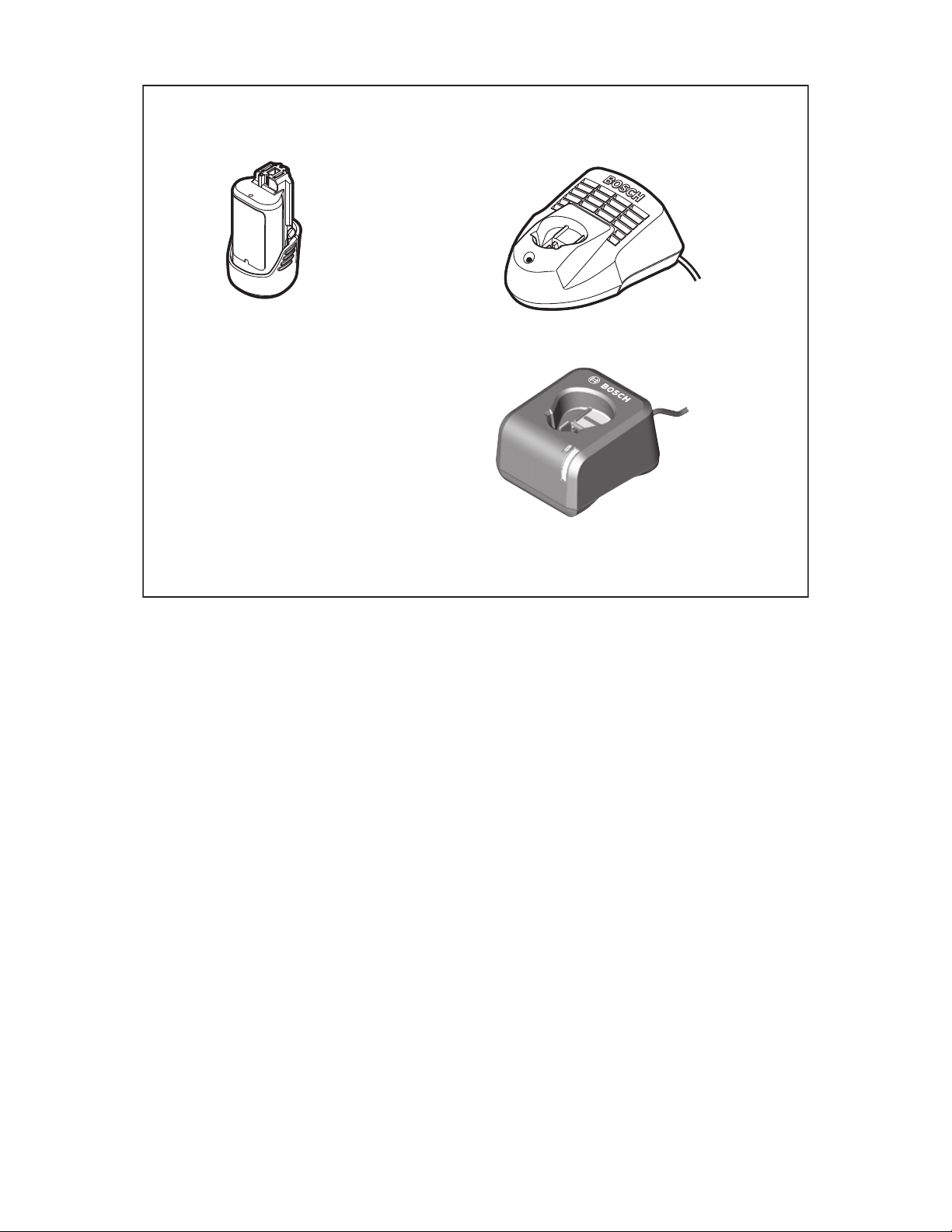
BAT414
BAT415
BC330
BC430
GAL 12V-20
-7-
Find Quality Products Online at: sales@GlobalTestSupply.com
www.GlobalTestSupply.com

Safety Symbols
The definitions below describe the level of severity for each signal word. Please read the
manual and pay attention to these symbols.
This is the safety alert symbol. It is used to alert you to potential
personal injury hazards. Obey all safety messages that follow this
symbol to avoid possible injury or death.
Read manual symbol - Alerts user to read manual.
WARNING indicates a hazardous situation which, if not avoided,
could result in death or serious injury.
This symbol designates that this laser leveling tool complies with Part
15 of the FCC Rules.
General Safety Rules
Read all instructions. Failure to follow all instructions listed below may
result in hazardous radiation exposure, electric shock, fire and/or
serious injury.
SAVE ALL WARNINGS AND INSTRUCTIONS FOR FUTURE REFERENCE
The term “tool” in all of the warnings listed below refers to your mains-operated (corded) tool or
battery-operated (cordless) tool.
The following labels are on your laser tool for your convenience and
safety. They indicate where the laser light is emitted by the tool.
ALWAYS BE AWARE of their location when using the tool.
GCL100-80C
IEC 60825-1:2014-05
<10mW, 630- 650 nm | <1mW, 630-65 0 nm
LASER RADIATION. DO NOT STARE INTO BEAM. CLASS 2 LASER PRODUCT.
COMPLIES WITH 21 CFR 1040.10 AND 1040.11 EXCEPT FOR DEVIATIONS PURSUANT
TO LASER NOTICE 50, 6/24/2007
RADIACIÓN LÁSER. NO MIRE AL RAYO. PRODUCTO LÁSER DE CLASE 2. CUMPLE CON
LAS NORMAS 21 CFR 1040.10 Y 1040.11, EXCEPTO POR LAS DESVIACIONES
CONFORME AL AVISO PARA LÁSERES 50 DEL 24 DE JUNIO DE 2007
RAYONNEMENT LASER. NE REGARDEZ PAS DIRECTEMENT DANS LE FAISCEAU. PRODUIT
LASER DE CLASSE 2. CONFORME À 21 CFR 1040.10 ET 1040.11, SAUF POUR LES
ÉCARTS SUIVANT L'AVIS LASER 50, 24/6/2007
2
LASER RADIATION. DO NOT STARE INTO BEAM. CLASS 2 LASER PRODUCT.
COMPLIES WITH 21 CFR 1040.10 AND 1040.11 EXCEPT FOR DEVIATIONS PURSUANT
TO LASER NOTICE 50, 6/24/2007
RADIACIÓN LÁSER. NO MIRE AL RAYO. PRODUCTO LÁSER DE CLASE 2. CUMPLE CON
LAS NORMAS 21 CFR 1040.10 Y 1040.11, EXCEPTO POR LAS DESVIACIONES
CONFORME AL AVISO PARA LÁSERES 50 DEL 24 DE JUNIO DE 2007
RAYONNEMENT LASER. NE REGARDEZ PAS DIRECTEMENT DANS LE FAISCEAU. PRODUIT
LASER DE CLASSE 2. CONFORME À 21 CFR 1040.10 ET 1040.11, SAUF POUR LES
ÉCARTS SUIVANT L'AVIS LASER 50, 24/6/2007
GCL100-80CG
IEC 60825-1:2014-05
<10mW, 500-54 0 nm | <1mW, 630-650 nm
2
Do not direct the laser beam at persons or animals and do not stare into
the laser beam yourself. This tool produces laser class 2 laser radiation and
complies with 21 CFR 1040.10 and 1040.11 except for deviations pursuant
to Laser Notice No. 50, dated June 24, 2007. This can lead to persons being
blinded.
DO NOT remove or deface any warning or caution labels. Removing labels increases the
risk of exposure to laser radiation.
Use of controls or adjustments or performance of procedures other than those specified in this
manual, may result in hazardous radiation exposure.
ALWAYS make sure that any bystanders in the vicinity of use are made aware of the
dangers of looking directly into the laser tool.
DO NOT place the laser tool in a position that may cause anyone to stare into the laser
beam intentionally or unintentionally. Serious eye injury could result.
-8-
Find Quality Products Online at: sales@GlobalTestSupply.com
www.GlobalTestSupply.com

ALWAYS position the laser tool securely.
Damage to the laser tool and/or serious injury
to the user could result if the laser tool fails.
ALWAYS use only the accessories that are
recommended by the manufacturer of your
laser tool. Use of accessories that have been
designed for use with other laser tools could
result in serious injury.
DO NOT use this laser tool for any purpose
other than those outlined in this manual.
This could result in serious injury.
DO NOT leave the laser tool “ON”
unattended in any operating mode.
DO NOT disassemble the laser tool. There
are no user serviceable parts inside. Do not
modify the product in any way. Modifying
the laser tool may result in hazardous laser
radiation exposure.
DO NOT use the laser viewing glasses as
safety goggles. The laser viewing glasses
are used for improved visualization of the laser
beam, but they do not protect against laser
radiation.
DO NOT use the laser viewing glasses as
sun glasses or in traffic. The laser viewing
glasses do not afford complete UV protection
and reduce color perception.
DO NOT use any optical tools such as, but
not limited to, telescopes or transits to view
the laser beam. Serious eye injury could result.
DO NOT stare directly at the laser beam or
project the laser beam directly into the eyes
of others. Serious eye injury could result.
Work area safety
Keep work area clean and well lit. Cluttered
or dark areas invite accidents.
DO NOT operate the laser tool around
children or allow children to operate the
laser tool. Serious eye injury could result.
DO NOT use laser tools, attachments and
accessories outdoors when lightning
conditions are present.
Do not operate the laser tool in explosive environments, such as in the presence of flammable liquids, gases or dusts. Sparks can be
created in the laser tool which may ignite the
dust or fumes.
Electrical safety
Batteries can explode or
leak, cause injury or fire.
To reduce this risk, always follow all instructions
and warnings on the battery label and package.
DO NOT expose the laser tool and battery to
rain or wet conditions. Water entering laser
tool will increase the risk of fire and personal
injury.
DO NOT short any battery terminals.
DO NOT mix battery chemistries.
Dispose of or recycle batteries per local code.
DO NOT dispose of batteries in fire.
Keep batteries out of reach of children.
Remove batteries if the device will not be used
for several months.
Personal safety
If laser radiation strikes your eye, you must
deliberately close your eyes and immediately turn your head away from the beam.
Do not make any modifications to the laser
equipment.
Stay alert, watch what you are doing and
use common sense when operating a tool.
Do not use a tool while you are tired or
under the influence of drugs, alcohol or
medication. A moment of inattention while
operating a tool may result in serious personal
injury or incorrect measurement results.
Use safety equipment. Always wear
eye protection. Safety equipment such as
dust mask, non-skid safety shoes, hard hat,
or hearing protection used for appropriate
conditions will reduce personal injuries.
Use caution when using laser tools in the
vicinity of electrical hazards.
Prevent unintentional starting. Ensure the
switch is in the off-position before inserting
batteries. Accidental energizing laser tool that
have the switch on invites accidents.
Magnets
Keep the tool, positioning
device RM 2 (18), BM 1 (21),
laser receiver LR 6/LR8 (25), and
laser target plate (24) away from
cardiac pacemakers. The
magnets of the tool and laser target plate
generate a field that can impair the function of
cardiac pacemakers.
Keep the tool, positioning device
RM 2 (18), BM 1 (21), laser receiver
LR 6/LR8 (25), and laser target plate (24)
-9-
Find Quality Products Online at: sales@GlobalTestSupply.com
www.GlobalTestSupply.com

away from magnetic data medium and
magnetically-sensitive equipment. The
effect of the magnets of the tool and laser
target plate can lead to irreversible data
loss.
Use and care
Use the correct tool for your application.
The correct tool will do the job better
and safer.
Do not use the tool if the switch does not
turn it on and off. Any tool that cannot be
controlled with the switch is dangerous and
must be repaired.
Store idle tool out of the reach of children
and do not allow persons unfamiliar with
the tool or these instructions to operate
the tool. Tools are dangerous in the hands of
untrained users.
Maintain tools. Check for misalignment or
binding of moving parts, breakage of parts
and any other condition that may affect the
operation. If damaged, tool repaired before
use. Many accidents are caused by poorly
maintained tools.
Use the tool, accessories, etc., in
accordance with these instructions and in
the manner intended for the particular type
of tool, taking into account the working
conditions and the work to be performed.
Use of the tool for operations different from
those intended could result in a hazardous
situation.
Battery tool use and care
Recharge only with the charger specified by
the manufacturer. A charger that is suitable for
one type of battery pack may create a risk of
fire when used with another battery pack.
Use laser tools only with specifically
designated battery packs. Use of any other
battery packs may create a risk of injury and fire.
When battery pack is not in use, keep it
away from other metal objects like paper
clips, coins, keys, nails, screws, or other
small metal objects that can make a
connection from one terminal to another.
Shorting the battery terminals together may
cause burns or a fire.
Under abusive conditions, liquid may be
ejected from the battery; avoid contact.
If contact accidentally occurs, flush with
water. If liquid contacts eyes, additionally
seek medical help. Liquid ejected from the
battery may cause irritation or burns.
Do not use a battery pack or tool that is
damaged or modified. Damaged or modified
batteries may exhibit unpredictable behavior
resulting in fire, EXPLOSION or risk of injury.
Do not expose a battery pack or tool to fire
or excessive temperature. Exposure to fire or
temperature above 265 °F (130 °C) may cause
explosion.
Follow all charging instructions and
do not charge the battery pack or tool
outside the temperature range specified in
the instructions. Charging improperly or at
temperatures outside the specified range may
damage the BATTERY and increase the risk
of fire.
Disconnect the battery pack from the tool
before making any adjustments, changing
accessories, or storing the tool. Such
preventive safety measures reduce the risk of
starting the tool accidentally.
Do not modify or attempt to repair the tool
or the battery pack except as indicated in
the instructions for use and care.
Service
Have your tool serviced by a qualified
repair person using only identical
replacement parts. This will ensure that the
safety of the tool is maintained.
Develop a periodic maintenance schedule
for tool. When cleaning a tool be careful not
to disassemble any portion of the tool since
internal wires may be misplaced or pinched
or may be improperly mounted. Certain
cleaning agents such as gasoline, carbon
tetrachloride, ammonia, etc. may damage
plastic parts.
SAVE THESE INSTRUCTIONS.
-10-
Find Quality Products Online at: sales@GlobalTestSupply.com
www.GlobalTestSupply.com

Bluetooth®
Do not use the laser tool with Bluetooth®
in the vicinity of gas stations, chemical
plants, areas where there is danger of explosion and areas subject to blasting. Do
not use the laser measure with Bluetooth®
in airplanes. Do not use the laser measure
with Bluetooth® in the vicinity of medical
devices. Avoid operation in the direct vicinity of the human body over longer periods
FCC Caution
The manufacturer is not responsible for radio interference caused
by unauthorized modifications to
this equipment. Such modifications could void
the user’s authority to operate the equipment.
This device complies with Part 15 of the FCC
Rules. Operation is subject to the following
two conditions:
1) This device may not cause harmful inter-
ference, and
2) This device must accept any interference
received, including interference that may
cause undesired operation.
NOTE! This equipment has been tested and
found to comply with the limits for a Class
B digital devices, pursuant to Part 15 of the
FCC rules. These limits are designed to provide reasonable protection against harmful
interference in a residential installation. This
equipment generates uses and can radiate
radio frequency energy and, if not installed
and used in accordance with the instructions,
may cause harmful interference to radio communications. However, there is no guarantee
of time. When using the laser measure with
Bluetooth®, interference with other devices
and systems, airplanes and medical devices
(e.g., cardiac pacemakers, hearing aids) may
occur.
The Bluetooth® word mark and logos are registered trademarks owned by Bluetooth SIG,
Inc. and any use of such marks by Robert
Bosch Tool Corporation is under license.
that interference will not occur in a particular installation. If this equipment does cause
harmful interference to radio or television reception, which can be determined by turning
the equipment off and on, the user is encouraged to try to correct the interference by one
or more of the following measures:
t 3FPSJFOUPSSFMPDBUFUIFSFDFJWJOHBOUFOOB
t *ODSFBTFUIFTFQBSBUJPOCFUXFFOUIFFRVJQ-
ment and receiver.
t $POOFDUUIFFRVJQNFOUJOUPBOPVUMFUPOB
circuit different from that to which the receiver is connected.
t $POTVMUUIFEFBMFSPSBOFYQFSJFODFESBEJP
TV technician for help.
“Exposure to Radio Frequency (RF) Signals:
The wireless device is a radio transmitter and
receiver. It is designed and manufactured not
to exceed the emission limit for exposure to
radio frequency (RF) energy set by the Ministry of Health (Canada), Safety Code 6. These
limits are part of comprehensive guidelines
and established permitted levels of RF energy
for the general population.
Industry Canada (IC)
This device complies with Industry Canada’s licence-exempt RSSs. Operation is subject to the
following two conditions:
(1) This device may not cause interference; and
(2) This device must accept any interference, including interference that may cause undesired
operation of the device.
Intended Use
The tool is intended for determining and checking horizontal and vertical lines as well as plumb
points. The measuring tool is suitable for indoor and outdoor use.
-11-
Find Quality Products Online at: sales@GlobalTestSupply.com
www.GlobalTestSupply.com

Features
The numbering of the product features shown refers to the illustration of the tool on the graphic page.
1 Exit opening for laser
beam
2 Indicator for Bluetooth
®
connection
3 Bluetooth
®
button
4 Charging condition of
battery pack
5 Working without automatic
leveling indicator
6 Receiver mode button
7 Receiver mode indicator
8 Button for laser operating
9 Battery pack*
10 Laser warning label
11 Serial number
12 Tripod mount 1/4”
13 Guide groove
14 On/Off switch
15 Guide rail
16 Magnets
17 Fastening slot
18 Rotating mount (RM 2)*
19 Fine adjustment knob of
rotating platform
20 Ceiling clip (BM 3)*
21 Positioning device BM 1*
22 Laser viewing glasses*
23 Protective pouch*
24 Laser target plate
25 Laser receiver*
26 Hard Carrying Case*
27 Tripod BT 150*
28 Telescopic rod BP350*
mode
*The accessories illustrated or described are not included as standard delivery.
Technical Data
Laser Model GCL100-80C GCL100-80CG
1)
Working range (typical)
–without laser receiver
–with laser receiver
–Upward laser point
ward laser point
–Down
Leveling Accuracy
–Laser lines
–Laser points
Self-leveling range (typical) ±4° ±4°
Leveling duration (typical) <4s <4s
Operating temperature 14 °F ~122 °F
St
orage temperature
–Laser Level
–Battery
Charging t
Max. altitude 6560 ft (2000 m) 6560 ft (2000 m)
Relative air humidity, max. 90 % 90 %
Pollution degree according IEC
61010
Laser class 22
emperature 32 °F ~ 113 °F
4)
up to 100 f
15-165 ft (5-50 m)
30 ft (10 m)
30 ft (10 m)
±1/8 in. at 30 ft (3 mm at 10 m)
±9/32 in. at 30 ft (7 mm at 10 m)
(–10 °C ~ +50 °C)
-4 °F ~ 158 °F (–20 °C ~ +70 °C)
32 °F ~122 °F (0 °C ~ +50 °C)
(0 °C ~ +45 °C)
22
t (30 m)
up to 100 ft (30 m)
15-165 ft (5-50 m)
30 ft (10 m)
30 ft (10 m)
±1/8 in. at 30 ft (3 mm at 10 m)
±9/32 in. at 30 ft (7 mm at 10 m)
14 °F ~122 °F
(–10 °C ~ +50 °C)
-4 °F ~ 158 °F (–20 °C ~ +70 °C)
32 °F ~122 °F (0 °C ~ +50 °C)
32 °F ~ 113 °F
(0 °C ~ +45 °C)
-12-
Find Quality Products Online at: sales@GlobalTestSupply.com
www.GlobalTestSupply.com

Laser Model GCL100-80C GCL100-80CG
Laser type
–Line
–Point
ipod mount 1/4”-20 1/4”-20
Tr
Laser tool power supply
– Battery pack (lithium-ion)
Battery Charger List
–Rechar
geable Batteries
–Chargers
630-650 nm, <10 mW
630-650 nm, <1 mW
10.8 V/12 V
BAT414, BAT415
BC330, BC430
GAX18V-30, GAL 12V-20
500-540 nm, <10 mW
630-650 nm, <1 mW
10.8 V/12 V
BAT414, BAT415
BC330, BC430
GAX18V-30, GAL 12V-20
Compatible laser receivers LR 6, LR8 LR8
®
Bluetooth
laser tool
–Compatibility
Bluetooth® smartphone
–Compatibility
–Operating system
Bluetooth
®
(Low Energy)
Bluetooth
®
(Low Energy)
Android 4.3 (and above)
iOS 7 (and above)
2)
Bluetooth
®
(Low Energy)
2)
Bluetooth
®
(Low Energy)
Android 4.3 (and above)
iOS 7 (and above)
Weight 1.4 lb (0.62 kg) 1.4 lb (0.62 kg)
Dimensions 5.4” x 4.8” x 2.2”
(136 x 122 x 55 mm)
Degree of protection
3)
IP 54 (dust and splash
water protected)
5.4” x 4.8” x 2.2”
(136 x 122 x 55 mm)
IP 54 (dust and splash
water protected)
2)
2)
1) The working range can be decreased by unfavourable environmental conditions (e.g. direct sun irradiation).
2) For Bluetooth® low energy devices, establishing a connection may not be possible, depending on model and operating system.
Bluetooth® devices must support the SPP profile.
3) Battery port and battery packs not included.
4) Conductive pollution occurs, or dry, non-conductive pollution occurs which becomes conductive due to condensation, which is
expected. In such conditions, equipment is normally protected against exposure to direct sunlight, precipitation, and full wind
pressure, but neither temperature nor humidity is controlled.
Technical data determined with battery from delivery scope (BAT414).
The laser tool can be clearly identified with the serial number 11 on the type plate.
-13-
Find Quality Products Online at: sales@GlobalTestSupply.com
www.GlobalTestSupply.com

Preparation
Laser Tool Power Supply
The laser tool can only be operated with a
Bosch rechargeable lithium-ion battery pack.
Operation with Bosch Rechargeable
Lithium-ion Battery Pack
Use only Bosch
rechargeable lithium-ion
battery packs listed in the technical data
section of this manual. Use of other battery
packs may increase the risk of fire, personal
injury and property damage.
Note: The battery pack is supplied partially
charged. To ensure full capacity of the
battery pack, completely charge the battery
pack in the battery charger before using for
the first time.
Use only Bosch
chargers listed in the
technical data section of this manual. Use
of other chargers may increase the risk of
fire, personal injury and property damage.
The lithium-ion battery pack can be charged
at any time without reducing its service life.
Interrupting the charging procedure does not
damage the battery pack.
The “Electronic Cell Protection (ECP)”
protects the lithium-ion battery pack against
deep discharging. When the battery pack is
discharged, the laser tool is switched off by a
protective circuit.
tDo not switch the laser tool back on
after it has been switched off by the
protective circuit. The battery pack can be
damaged.
To insert the charged battery pack 9, align
battery pack and slide it into the battery port
until it locks into position. Don’t force.
To remove the battery pack 9, press the
battery release tabs and pull the battery pack
out of the battery port. Do not use force to
do this.
Battery Status Indicator
The battery status indicator 4 shows the
charge condition of the battery pack or
batteries:
LED Charge Condition
Continuous lighting, green 100–75 %
Continuous lighting, yello
Continuous lighting, red 35–10 %
No light – Battery pack defective
If the battery pack is running low, the laser lines will
gradually become dimmer.
Immediately replace a fault battery pack.
w 75–35 %
– Batteries empty
Working with Rotating Mount RM2
(see figures A1 – A3)
You can use the rotating mount 18 to rotate
the measuring tool 360° around a central,
always visible plumb point. This enables
you to align the laser lines precisely,
without having to change the position of the
measuring tool.
You can use the fine adjustment knob 19
to align vertical laser lines precisely with
reference points.
Place the measuring tool with the guide
groove 13 on the guide rail 15 of the rotating
mount 18 and slide the measuring tool to the
stop onto the platform.
To disconnect, pull the measuring tool in the
opposite direction from the rotating mount.
Positioning possibilities of the rotating mount:
– standing on a flat surface,
– screwed to a vertical surface,
– on metallic surfaces using the magnets 16,
– on metallic ceiling strips using the ceiling
clip 20.
-14-
Find Quality Products Online at: sales@GlobalTestSupply.com
www.GlobalTestSupply.com

Operation
Initial Operation
t 1SPUFDU UIF UPPM BHBJOTUNPJTUVSF BOE
direct sun light.
t %P OPU TVCKFDU UIF UPPM UP FYUSFNF
temperatures or variations in
temperature. As an example, do not leave
it in vehicles for longer periods. In case of
large variations in temperature, allow the
tool to adjust to the ambient temperature
before putting it into operation. In case of
extreme temperatures or variations in
temperature, the accuracy of the tool can
be impaired.
t "WPJEIFBWZ JNQBDU PS ESPQQJOHPGUIF
tool. After heavy exterior impact on the
tool, an accuracy check should always be
carried out before continuing to work (see
“Leveling Accuracy”).
t 4XJUDI UIF UPPM PGG EVSJOH USBOTQPSU
When switching off, the leveling unit is
locked to help prevent damage in case of
intense movement.
Switching On and Off
Do not point the laser
beam at persons
or animals and do not look into the laser
beam yourself, not even from a large
distance.
Do not leave the
switched on tool
unattended and switch the tool off after
use.
To switch on the measuring tool, slide the
On/Off switch 14 to position “On
working without automatic leveling) or to
position “On
leveling). As soon as it is switched on, the
measuring tool emits laser lines from the exit
openings 1.
To switch off the measuring tool, slide the
On/Off switch 14 to position “Off”.
The pendulum unit is locked when the tool is
switched off.
When exceeding the maximum permitted
operating temperature of 122 °F (50 °C), the
measuring tool switches off to protect the
laser diode. After cooling down, the measuring
tool is ready for operation and can be
switched on again.
” (for working with automatic
” (for
Automatic Shut-off
When no button on the measuring tool
is pressed for approx. 120 minutes, the
measuring tool automatically switches off to
save the batteries.
To switch the measuring tool back on after
automatic shut-off, you can either slide the
On/Off switch 14 to position “Off” first and
then switch the measuring tool back on, or
press button 8.
Temporarily Deactivating Automatic
Shut-Off
To deactivate automatic shut-off, hold down
button 8 for at least 3 s with the measuring
tool switched on. If automatic shut-off is
deactivated, the laser lines will flash briefly as
confirmation.
Note: If the operating temperature exceeds
113°F (45°C), automatic shut-off can no
longer be deactivated.
After the next time the measuring tool is
switched off and on, the automatic shut-off will
be activated again.
Setting the operating mode
(see figures B1–F1)
The measuring tool has several operating
modes between which you can switch at any
time:
– Cross-line and point operation: The
measuring tool generates a horizontal
and a vertical laser line facing frontward,
a vertical laser point facing upward and a
vertical laser point facing downward.
The laser lines cross at a 90° angle.
– Horizontal line operation: The measuring
tool generates a horizontal laser line facing
frontward.
– Vertical line operation: The measuring
tool generates a vertical laser line facing
frontward.
If the measuring tool is positioned in the
room, the vertical laser line is displayed on
the ceiling beyond the upper laser point.
If the measuring tool is positioned directly
against a wall, the vertical laser line
generates an almost completely allround
laser line (360° line).
-15-
Find Quality Products Online at: sales@GlobalTestSupply.com
www.GlobalTestSupply.com

– Point operation: The measuring tool
generates a vertical laser point facing
upward and a vertical laser point facing
downward.
Use button 8 to switch between the individual
operating modes, see table on page 24.
All modes except for point operation can be
selected both with and without automatic
leveling.
Receiver Mode
Receiver mode must be activated to work with
the laser receiver 25, –regardless of which
operating mode is selected–.
In receiver mode the laser lines flash at very
high frequency, enabling them to be detected
by the laser receiver 25.
To switch on receiver mode, press button 6.
Indicator 7 will light up green.
When receiver mode is switched on, the
laser lines are less visible to the human eye.
For this reason, switch receiver mode off by
pressing button 6 again to work without a
laser receiver. Indicator 7 will extinguish.
Automatic Leveling
Working with Automatic Leveling
(see figures B1–E1)
After switching on, the leveling function
automatically compensates irregularities
within the self-leveling range of ±4°. The
measuring tool is leveled in as soon as the
laser lines no longer flash.
If the automatic leveling function is not
possible, e.g. because the surface on which
the measuring tool stands deviates by more
than 4° from the horizontal plane, the laser
beams flash. In this case, bring the measuring
tool to the level position and wait for the selfleveling to take place.
In case of ground vibrations or position
changes during operation, the measuring tool
is automatically leveled in again. To avoid
errors by moving the measuring tool, check
the position of the laser beams with regard to
the reference points upon re-leveling.
Position the measuring tool on a level, firm
support or attach it to the rotating mount 18.
For work with automatic leveling, slide the On/
Off switch 14 to position “On
If the measuring tool is outside of the selfleveling range, the laser lines and/or points
will flash quickly.
If you deactivate automatic leveling (On/Off
switch 14 to position “On
tool will switch to cross-line operation.
”.
”), the measuring
Working with Automatic Levelling
On/Off switch 14 in position
“”
Laser
Press 1 time – – C1
Laser
Press 2 times
Laser
Press 3 times
Laser
Press 4 times
Horizontal line
operation
Cross-line operation
– – D1
– – E1
Cross-line operation
Vertical line
operation
Point
operation
Indicator 5 for working
without automatic levelling
-16-
Figure
B1
B1
Find Quality Products Online at: sales@GlobalTestSupply.com
www.GlobalTestSupply.com

Working without Automatic Leveling
(see figure F1)
When automatic leveling is switched off, you
can hold the measuring tool freely in your
hand or place it on an inclined surface. The
laser beams no longer necessarily run vertical
to each other.
Working without Automatic Levelling
Horizontal line
operation
On/Off switch 14 in position
“”
Laser
Press 1 time – –red
Laser
Press 2 times
–
Cross-line operation
– –red
Vertical line
operation
For work without automatic leveling, slide the
On/Off switch 14 to position “On
”.
The laser lines will flash slowly.
If you activate automatic leveling (On/Off
switch 14 to position “On
”), the measuring
tool will switch to cross-line operation with
point operation.
Point
operation
Indicator 5 for working
without automatic levelling
red F1
Figure
Laser
Press 3 times
–
Cross-line operation
Remote control via
the “Leveling Remote App”
The laser tool is equipped with a Bluetooth®
module which uses radio technology to
enable remote control via a smartphone with a
Bluetooth
The “Leveling Remote App” application
(app) is needed to use this function. You
can download this in the app store for your
terminal device (Apple App Store, Google Play
Store).
For information on the necessary system
requirements for a Bluetooth
please refer to the Bosch website.
When remote controlling by means of
Bluetooth
mobile terminal/device and laser tool as a
result of poor reception conditions.
Switching On Bluetooth
remotely using the Bosch app
without line of sight to the laser tool. The
sudden bright laser beam may increase the
risk of personal injury or property damage.
®
interface.
®
connection,
®
, time lags may occur between
®
Do not turn on laser
red F1
Ensure there are no bystanders in the direct
path of the laser beam before turning on the
laser remotely.
®
To switch on Bluetooth
control, press the Bluetooth
that the Bluetooth
®
interface is activated on
for the remote
®
-button 3. Ensure
your mobile terminal/device.
After starting the Bosch application, the
connection between the mobile terminal/
device and the laser tool is established. When
several active laser tools are found, select
the appropriate laser tool. When only one
active laser tool is found, the connection is
automatically established.
The connection is established as soon as the
Bluetooth
The Bluetooth
®
indicator 2 lights up.
®
connection may be
interrupted if there is too much distance or
there are obstacles between laser tool and
mobile terminal/device and if there are any
electromagnetic interference sources. In this
case, the Bluetooth
Switching Off Bluetooth
To switch off Bluetooth® for the remote
control, press the Bluetooth
®
indicator flashes.
®
®
-button 3 or
switch off the laser tool.
-17-
Find Quality Products Online at: sales@GlobalTestSupply.com
www.GlobalTestSupply.com

Accuracy Check of the Laser Tool
Influences on Accuracy
The ambient temperature has the greatest
influence. Especially temperature differences
occurring from the ground upward can divert
the laser beam.
Because the largest difference in temperature
layers is close to the ground, the tool
should always be mounted on a tripod when
distances exceeding 65 ft (20 m). If possible,
also set up the tool in the center of the work
area.
Apart from exterior influences, device-specific
influences (such as heavy impact or falling
down) can lead to deviations. Therefore,
check the accuracy of the tool each time
before starting your work.
Firstly, check the leveling accuracy of the
horizontal laser line and then the leveling
accuracy of the vertical laser line.
Should the tool exceed the maximum
deviation during one of the tests, please have
it repaired by a Bosch after-sales service.
A
B
180°
– Turn the tool by 180°, allow it to level in and
mark the cross point of the laser lines on
the opposite wall B (point II).
– Without turning the tool, position it close to
wall B. Switch the tool on and allow it to
level in.
A
B
Checking the Height Accuracy
of the Horizontal Line
A free measuring distance of 16 ft (5 m) on
a firm surface in front of two walls A and B is
required for the check.
– Mount the tool onto a tripod, or place it on a
firm and level surface close to the wall A.
Switch the tool on. Select cross-line
operation with automatic leveling.
A
16 ft (5 m)
– Direct the laser against the close wall A and
allow the tool to level in. Mark the center of
the point where the laser lines cross each
other on the wall (point I).
B
– Align the height of the tool (using a tripod or
by underlaying, if required) in such a
manner that the cross point of the laser
lines is projected against the previously
marked point II on the wall B.
A
d
– Without changing the height, turn around
the tool by 180°. Direct it against the wall A
in such a manner that the vertical laser line
runs through the already marked point I.
Allow the tool to level in and mark the cross
point of the laser lines on the wall A (point III).
– The difference d of both marked points I
and III on wall A results in the actual height
deviation of the tool.
180°
B
-18-
Find Quality Products Online at: sales@GlobalTestSupply.com
www.GlobalTestSupply.com

The maximum permitted deviation dmax can
5
be calculated as follows:
MAX = double the distance between the walls
d
x 0.004 in/ft
Example: If the distance between the walls is
16 ft (5 m), the maximum deviation is
MAX = 2 x 16 ft x 0.004 in/ft = 1/8 in. The
d
marks must therefore be maximum 1/8 in.
apart.
Checking the Leveling Accuracy
of the Horizontal Line
For the check, a free surface of approx. 16 x
16 ft (5 x 5 m) is required.
– Set up the measuring tool on a firm, level
surface between both walls A and B. Allow
the measuring tool to level in while in
horizontal operation.
A
16 ft (5 m)
8 ft (2.5 m)
– At a distance of 8 ft (2.5 m) from the
measuring tool, mark the centre of the laser
line (point I on wall A and point II on wall B)
on both walls.
B
– Align the height of the measuring
tool (using a tripod or by underlaying, if
required) in such a manner that the centre
of the laser line is projected exactly against
the previously marked point II on wall B.
– Mark the centre of the laser line as point
III (vertically above or below point I) on the
wall A.
– The difference d of both marked points
I and III on wall A indicates the actual
deviation of the measuring tool from the
level plane.
The maximum permitted deviation dmax can
be calculated as follows:
MAX = double the distance between the walls
d
x 0.004 in/ft
Example: If the distance between the walls is
16 ft (5 m), the maximum deviation is
MAX = 2 x 16 ft x 0.004 in/ft = 1/8 in. The
d
marks must therefore be maximum 1/8 in.
apart.
Checking the Leveling Accuracy
of the Vertical Line
For this check, a door opening is required
with at least 8 ft (2.5 m) of space (on a firm
surface) to each side of the door.
– Position the tool on a firm, level surface
(not on a tripod) 8 ft (2.5 m) away from
the door opening. Allow the tool to level in
while in vertical operation with automatic
leveling, and direct the laser beam at the
door opening.
A
d
8 ft (2.5 m)
16 ft (5 m)
5,0 m
2,5 m
8 ft (2.5 m)
8 ft (2.5 m)
B
– Set up the measuring tool 16 ft (5 m) away
turned by 180° and allow it to level in.
-19-
Find Quality Products Online at: sales@GlobalTestSupply.com
www.GlobalTestSupply.com

– Mark the center of the vertical laser line at
the floor of the door opening (point I), at
a distance of 16 ft (5 m) beyond the other
side of the door opening (point II) and at
the upper edge of the door opening (point
III).
d
6.5 ft (2 m)
Checking Plumb Accuracy
For this check, a free measuring distance of
approx. 16 ft (5m) between floor and ceiling
on a firm surface is required.
– Mount the measuring tool onto the rotating
mount and place it on the floor.
– Switch the measuring tool on and allow it to
level.
16 ft
(5 m)
– Rotate the tool by 180° and position it on
the other side of the door opening directly
behind point II. Allow the tool to level in and
align the vertical laser line in such a manner
that its center runs exactly through points I
and II.
– Mark the center of the laser line at the
upper edge of the door opening as point IV.
– The difference d of both marked points III
and IV results in the actual deviation of the
tool to the plumb line.
– Measure the height of the door opening.
The maximum admissible deviation is
calculated as follows:
Repeat the measuring procedure for the
second vertical laser plane. For this, select
an operating mode in which a vertical laser
plane is generated aside of the tool. Turn the
tool 90° before beginning with the measuring
procedure.
Doubled height of the door opening x 0.004
in/ft
Example: For a door-opening height of 6.5ft,
the maximum deviation may be
2 x 6.5 ft x ±0.004 in/ft = ±1/16 in.
Consequently, points III and IV may be
no more than 1/16 in (max.) apart from
each other.
– Mark the centre of the upper crossing point
on the ceiling (point I). Also mark the centre
of the bottom laser point on the floor (point II).
d
180°
– Rotate the measuring tool 180°. Position it
so that the centre of the lower laser point
is on the point II which has already been
marked. Allow the measuring tool to level.
Mark the centre of the upper laser point
(point III).
– The difference d of both marked points I and
III on the ceiling results in the actual deviation
of the measuring tool to the plumb line.
The maximum permitted deviation dmax can
be calculated as follows:
MAX = double the distance between floor and
d
ceiling x 0.009 in/ft
Example: If the distance from the floor to the
ceiling is 5m, the maximum deviation is
MAX = 2 x 16 ft x 0.009 in/ft = 9/32 in. The
d
marks must therefore be maximum 9/32 in.
apart.
-20-
Find Quality Products Online at: sales@GlobalTestSupply.com
www.GlobalTestSupply.com

Working Advice
t For marking, always use only the center
of the laser point or the laser line. The
size of the laser point as well as the width of
the laser line change with distance.
t The measuring tool is equipped with
a radio interface. Local operating
restrictions, e.g. in airplanes or
hospitals, are to be observed.
Working with the Tripod
(Accessory)
A tripod offers a stable, height-adjustable
support surface for measuring. Place
the measuring tool with the 1/4” tripod
mount 12 on the thread of the tripod 27 or
a conventional camera tripod. Tighten the
measuring tool using the locking screw of the
tripod.
Adjust the tripod roughly before switching on
the measuring tool.
Fastening with the Universal Holder
(Accessory) (see figure G)
With the BM 1 positioning device 21, you can
fasten the measuring tool, e.g., to vertical
surfaces, pipes or magnetisable materials.
The universal holder is also suitable for use
as a ground tripod and makes the height
adjustment of the measuring tool easier.
Adjust the BM 1 positioning device 21 roughly
before switching on the measuring tool.
Working with the Laser Target Plate
(see figure G)
The laser target plate 24 increases the
visibility of the laser beam under unfavourable
conditions and at large distances.
The reflective part of the laser target plate 24
improves the visibility of the laser line. Thanks
to the transparent part, the laser line is also
visible from the back side of the laser target
plate.
Laser Viewing Glasses
(Accessory)
The laser viewing glasses filter out ambient
light. This enhances the laser visibility for the
eye.
t %POPU VTFUIFMBTFSWJFXJOH HMBTTFTBT
safety goggles. The laser viewing glasses
are used for improved visualization of the
laser beam, but they do not protect against
laser radiation.
t %POPUVTFUIF MBTFSWJFXJOHHMBTTFTBT
sun glasses or in traffic. The laser
viewing glasses do not afford complete UV
protection and reduce color perception.
Work Examples
(see figures B2–F2, G and H)
Applicational examples for the measuring tool
can be found on the graphics pages.
Always position the measuring tool close to
the surface or edge you want to check, and
allow it to level in prior to each measurement.
Maintenance and Service
Store and transport the tool only in the
supplied protective case.
Keep the tool clean at all times.
Do not immerse the tool into water or other
fluids.
Wipe off debris using a moist and soft cloth.
Do not use any cleaning agents or solvents.
Regularly clean the surfaces at the exit
opening of the laser in particular, and pay
attention to any fluff of fibers.
If the tool should fail despite the care taken in
manufacturing and testing procedures, repair
should be carried out by an authorized aftersales service center for Bosch power tools.
Find Quality Products Online at: sales@GlobalTestSupply.com
www.GlobalTestSupply.com
In all correspondence and spare parts orders,
please always include the 10-digit article
number given on the type plate of the tool.
In case of repairs, send in the tool packed in
its protective pouch 23.
ENVIRONMENT PROTECTION
Recycle raw materials & batteries
instead of disposing of waste. The
unit, accessories, packaging &
used batteries should be sorted for
environmentally friendly recycling in accordance
with the latest regulations.
-21-

LIMITED WARRANTY OF BOSCH LASER AND
MEASURING TOOL PRODUCTS
Robert Bosch Tool Corporation (“Seller”) warrants to the original purchaser only, that all Bosch lasers and
measuring tools will be free from defects in material or workmanship for a period of one (1) year from date
of purchase. Bosch will extend warranty coverage to two (2) years when you register your product within
eight (8) weeks after date of purchase. Product registration card must be complete and mailed to Bosch
(postmarked within eight weeks after date of purchase), or you may register on-line. If you choose not to
register your product, a one (1) year limited warranty will apply to your product.
30 Day Money Back Refund or Replacement -
If you are not completely satisfied with the performance of your laser and measuring tools, for any reason,
you can return it to your Bosch dealer within 30 days of the date of purchase for a full refund
or replacement. To obtain this 30-Day Refund or Replacement, your return must be accompanied by the
original receipt for purchase of the laser or optical instrument product. A maximum of 2 returns per
customer will be permitted.
SELLER’S SOLE OBLIGATION AND YOUR EXCLUSIVE REMEDY under this Limited Warranty and, to
the extent permitted by law, any warranty or condition implied by law, shall be the repair or replacement of
parts, without charge, which are defective in material or workmanship and which have not been misused,
carelessly handled, or misrepaired by persons other than Seller or Authorized Service Center. To make a
claim under this Limited Warranty, you must return the complete Bosch laser or measuring tool,
transportation prepaid, to any BOSCH Factory Service Center or Authorized Service Center. Please
include a dated proof of purchase with your tool. For locations of nearby service centers, please use our
on-line service locator.
THIS WARRANTY PROGRAM DOES NOT APPLY TO TRIPODS AND RODS. Robert Bosch Tool
Corporation (“Seller”) warrants tripods and leveling rods for a period of one (1) year from date of purchase.
THIS LIMITED WARRANTY DOES NOT APPLY TO OTHER ACCESSORY ITEMS AND RELATED
ITEMS. THESE ITEMS RECEIVE A 90 DAY LIMITED WARRANTY.
To make a claim under this Limited Warranty, you must return the complete product, transportation
prepaid. For details to make a claim under this Limited Warranty please visit.
ANY IMPLIED WARRANTIES SHALL BE LIMITED IN DURATION TO ONE YEAR FROM DATE OF
PURCHASE. SOME STATES IN THE U.S., AND SOME CANADIAN PROVINCES DO NOT ALLOW
LIMITATIONS ON HOW LONG AN IMPLIED WARRANTY LASTS, SO THE ABOVE LIMITATION MAY
NOT APPLY TO YOU.
IN NO EVENT SHALL SELLER BE LIABLE FOR ANY INCIDENTAL OR CONSEQUENTIAL DAMAGES
(INCLUDING BUT NOT LIMITED TO LIABILITY FOR LOSS OF PROFITS) ARISING FROM THE SALE
OR USE OF THIS PRODUCT. SOME STATES IN THE U.S., AND SOME CANADIAN PROVINCES DO
NOT ALLOW THE EXCLUSION OR LIMITATION OF INCIDENTAL OR CONSEQUENTIAL DAMAGES,
SO THE ABOVE LIMITATION MAY NOT APPLY TO YOU.
THIS LIMITED WARRANTY GIVES YOU SPECIFIC LEGAL RIGHTS, AND YOU MAY ALSO HAVE
OTHER RIGHTS WHICH VARY FROM STATE TO STATE IN THE U.S., OR PROVINCE TO
PROVINCE IN CANADA AND FROM COUNTRY TO COUNTRY.
THIS LIMITED WARRANTY APPLIES ONLY TO PRODUCTS SOLD WITHIN THE UNITED STATES OF
AMERICA, CANADA AND THE COMMONWEALTH OF PUERTO RICO. FOR WARRANTY
COVERAGE WITHIN OTHER COUNTRIES, CONTACT YOUR LOCAL BOSCH DEALER OR
IMPORTER.
-22-
Find Quality Products Online at: sales@GlobalTestSupply.com
www.GlobalTestSupply.com
 Loading...