

Page 1

BOSCH CLOTHES DRYER GAS CONVERSION KIT INSTRUCTIONS
WARNING WARNING WARNING
FOR TYPE WAT1G DRYERS
The Bosch Clothes Dryer is manufactured for use with natural (city) gas. Installation of this kit
converts the dryer for use with propane gas with a manifold pressure of 11" wc, and supply pressure
between 11" and 14" wc. When the dryer is converted for use with propane gas by means of this kit,
the input rating will be 18,000 Btu/hr for altitudes up to 7,700 feet above sea level. For installations
at an altitude greater than 7,700 feet above sea level, contact a qualified service agency for derating
instructions.
THIS CONVERSION KIT SHALL BE INSTALLED BY A QUALIFIED SERVICE AGENCY IN
ACCORDANCE WITH THE MANUFACTURER’S INSTRUCTIONS AND ALL APPLICABLE CODES AND
REQUIREMENTS OF THE AUTHORITY HAVING JURISDICTION. THE INFORMATION IN THESE
INSTRUCTIONS MUST BE FOLLOWED TO MINIMIZE THE RISK OF FIRE OR EXPLOSION OR TO
PREVENT PROPERTY DAMAGE, PERSONAL INJURY, OR DEA TH. THE QUALIFIED SER VICE AGENCY
IS RESPONSIBLE FOR THE PROPER INST ALLATION OF THIS KIT. THE INSTALLA TION IS NOT
PROPER AND COMPLETE UNTIL THE OPERATION OF THE CONVERTED APPLIANCE IS CHECKED
AS SPECIFIED IN THE MANUFACTURER’S INSTRUCTIONS SUPPLIED WITH THIS KIT.
• These instructions are intended for use by qualified service technicians only. A qualified service technician
is any person or representative of a company who is 1) trained and experienced in the servicing of natural
gas and propane (LP gas) appliances, 2) familiar with the precautions for performing work on natural gas
and propane (LP gas) appliances, and 3) knowledgeable of the applicable municipal codes governing work
on natural gas and propane (LP gas) appliances.
• Do not use these instructions or the materials contained in the Bosch Clothes Dryer Gas Conversion Kit for
any other purpose than that for which they are intended, which is the conversion of the Bosch Gas Clothes
dryer from operation with natural gas to operation with propane (LP gas).
• Follow these instructions carefully to minimize the risk of death and/or serious injury by fire and/or
explosion.
• As Bosch has no control over the customer’s selection of the service technician who will perform the work
described in this manual, Bosch can not be held responsible for death, injury, or property damage that may
result from work performed improperly or from the use of inferior tools and/or materials.
THE CONVERSION SHALL BE CARRIED OUT IN ACCORDANCE WITH THE REQUIREMENTS OF THE
PROVINCIAL AUTHORITIES HAVING JURISDICTION AND IN ACCORDANCE WITH THE
REQUIREMENTS OF THE CSA B149.1, INSTALLATION CODE.
Carefully read and understand these instructions before attempting the appliance conversion.
SAVE THESE INSTRUCTIONS
1
Page 2
BOSCH CLOTHES DRYER
GAS CONVERSION KIT
INSTRUCTIONS
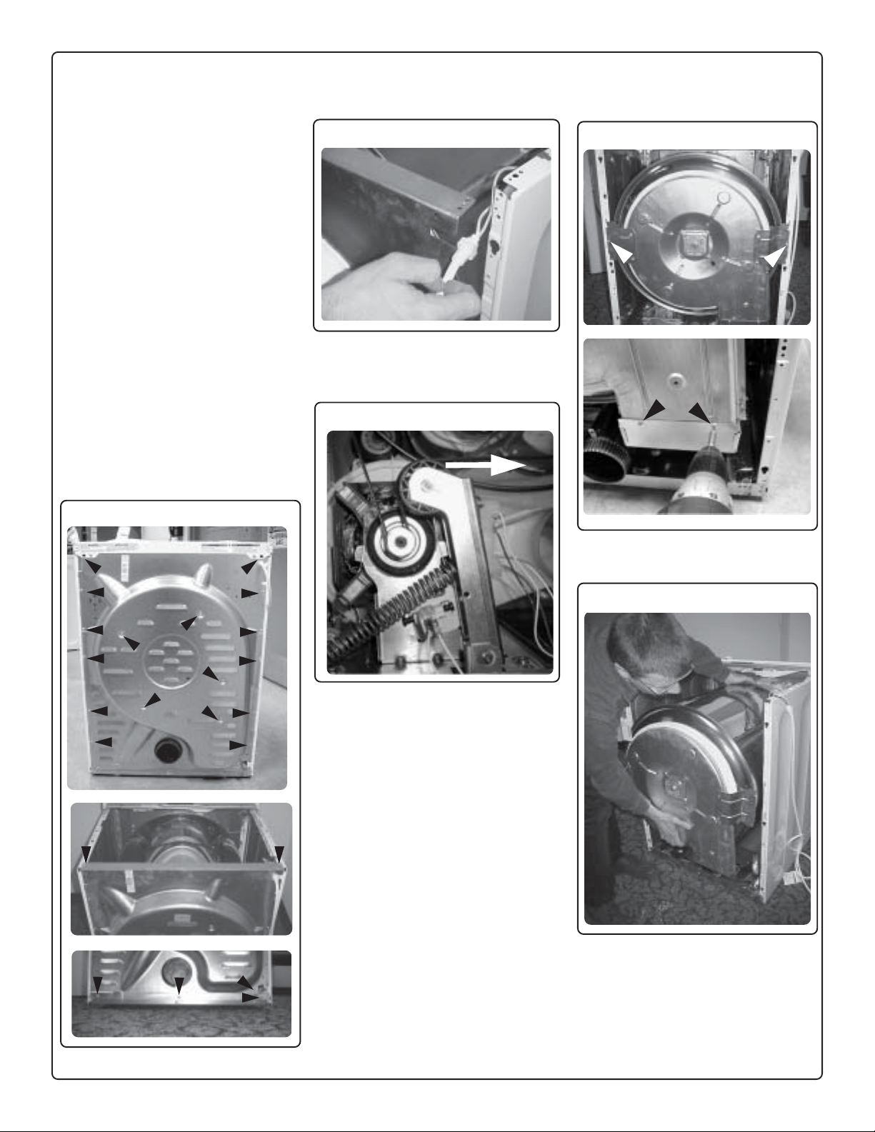
6) Remove the top panel and back
panel, being careful to remove the
power cord from the back panel as
shown in Figure 2.
8) Use a Torx T20 driver to remove the
four screws shown in Figure 4. Set
the screws aside for reinstallation
later.
1. Materials Supplied
• LP gas valve
• Label, Rating Plate
• Label, Conversion Record
• Instructions
2. Materials Needed
• T orx T20 driver
• 1” open-ended wrench
• Torque Wrench (English or metric)
• Torque Screwdriver (English or metric)
3. Procedure
1) Turn off the gas supply to the
dryer.
2) Disconnect the electrical power to
the dryer.
3) Disconnect the gas connection
from the dryer.
4) Move the dryer away from the wall.
5) Use a Torx T20 driver to remove
the screws on the back of the dryer
that secure the top panel and back
panel as shown in Figure 1. Set the
screws aside for reinstallation later.
Figure 1
Figure 2
7) Pull the tension lever to the right as
shown by the arrow in Figure 3,
and remove the belt from the drive
pulley.
Figure 3
Figure 4
9) Lift and remove the drum/hood
assembly as shown in Figure 5.
Figure 5
10) Carefully set the drum/hood
assembly aside.
2
Page 3

CAUTION
NTC Connector
11) Figure 6 shows the dryer interior with
the drum/hood assembly removed.
Figure 6
12) Locate gas valve and wire harness
connections shown in Figure 7.
Figure 7
14) Disconnect the two connectors of the
wire harness from the gas valve
as shown in Figure 9.
Figure 9
15) Disconnect the wires from the
Klixon shown in Figure 10.
Figure 10
17) Disconnect wires from the flame
sensor shown in Figure 12.
Figure 12
18) Disconnect the NTC connector
shown in Figure 13.
Figure 13
13) Use a 1” open-ended wrench to
disconnect the brass elbow from the
valve connection as shown in
Figure 8.
Figure 8
16) Disconnect the igniter wire shown in
Figure 11.
Figure 1 1
Igniter Wire
POSSIBLE DRYER DAMAGE: The
igniter can be damaged when the
combustion chamber is removed.
When removing the combustion
chamber, keep it away from the
igniter.
19) Remove the screw that connects the
combustion chamber to the burner
bracket shown in Figure 14.
Remove the combustion chamber
from the dryer.
Figure 14
3
Page 4

CAUTION
20) Figure 15 shows the burner
WARNING
assembly with an undamaged
igniter.
Figure 15
21) Use the service access to locate
and remove the screw from the side
of the burner bracket as shown in
Figure 16. Set the screw aside for
reinstallation later.
Figure 16
POSSIBLE DRYER DAMAGE: The
igniter can be damaged when the
burner bracket/ gas valve/igniter/
burner assembly is removed from
the dryer. Use caution when
removing the assembly from the
dryer.
23) Remove the burner bracket/ gas
valve/igniter/burner assembly from
the dryer.
24) Once the burner assembly has been
removed from the dryer, remove the
two screws that fasten the burner to
the burner bracket as shown in
Figure 18. Set the screws aside for
reinstallation later.
Figure 18
26) Remove the burner ring.
NOTE: The burner ring will not be
installed on the dryer when the dryer
is converted for use with propane.
However, retain the burner ring for
reinstallation should the dryer be
reconverted for use with natural
gas.
27) Remove the three screws that secure
the natural gas valve to the burner
bracket as shown in Figure 20. Set
the screws aside for reinstallation
later.
Figure 20
22) Remove the screw from the bottom
of the burner bracket as shown in
Figure 17. Set the screw aside for
reinstallation later.
Figure 17
25) Remove the two screws that fasten
the burner ring to the burner as
shown in Figure 19. Set the screws
aside for reinstallation later.
Figure 19
Burner Ring front view
FIRE/INJURY HAZARD: INSTALLING
A NON-LP GAS VALVE IN AN LP GAS
SYSTEM CAN CAUSE FIRE. MAKE
CERTAIN THAT THE LP GAS VALVE
IS INSTALLED WITH THE LP GAS
CONVERSION.
28) Identify the LP gas valve by the
label reading 25MO1A Type 190 at
the top, and Reg. 11.0” at the
bottom left corner.
29) Replace the natural gas valve with
the supplied LP valve. Use the three
previously removed screws to
secure the LP valve to the burner
bracket into the new gas valve.
Torque the screws to 2.6 p-f
(3.5 N-m.)
30) Reinstall the two screws into the
burner as shown in Figure 21.
Torque screws to 1.4 p-f (1.8N-m).
Figure 21
4
Page 5

31) Use the previously removed
screw to secure the burner bracket/
gas valve/igniter/burner assembly to
the dryer as shown in Figure 22.
34) Reconnect the NTC connector as
shown in Figure 25.
Figure 25
37) Reconnect the Klixon wires as shown
in Figure 28.
Figure 28
Figure 22
32) Reinstall the previously removed
burner bracket side screw as shown
in Figure 23.
Figure 23
NTC Connector
35) Reconnect the flame sensor wires
as shown in Figure 26.
Figure 26
38) Reconnect the gas valve wire
harness as shown in Figure 29.
Figure 29
33) Reinstall the combustion chamber
and secure it to the burner bracket
with the previously removed screw
as shown in Figure 24. Torque the
screw to 1.4 p-f (1.8N-m).
Figure 24
36) Reconnect the igniter wire as shown
in Figure 27.
Figure 27
Igniter Wire
39) Use a 1” open-ended wrench to
reconnect the brass elbow to the gas
valve fitting as shown in Figure 30.
Torque the connection to 25N-m.
Figure 30
5
Page 6

40) Reinstall the drum and rotation belt.
Make sure the rotation belt is tight.
Rotate the drum several times
(counter-clockwise, when facing
drum from rear of dryer) before
installing the back panel. This is
done to ensure that the belt is
installed correctly.
41) Reset the broken belt switch by
pressing it in the direction shown in
Figure 31.
Figure 31
48) Note the conversion on the supplied
Conversion Record Label, and afix
the Conversion Record Label and the
Rating Plate Label to the two
postions shown in Figure 32.
Figure 32
42) Install the back panel and top.
Torque all screws to 1.4 p-f
(1.8Nm).
43) Connect all gas connections and
power connections.
44) Pressure test the gas valve.
Remove the pressure tap plug from
the valve body. Insert a pressure tap
and connect a manometer to the
end of the nipple. Turn on the gas
supply and verify that the outlet
pressure is 11" ± .5” water column
(wc). Turn off the gas supply.
Disconnect the manometer and
replace the pressure tap with
the plug.
45) Leak check the dryer prior to
operation.Turn on the gas supply.
Brush or spray a soap and water
solution onto the pressure tap and
all gas connections. Growing
bubbles indicates leaks. If any
bubbles are present, tighten the
leaking connection and retest for
leakage.
46) Check the dryer operation, including
ignition sequence. The gas line
may have air in it, so more than one
ignition cycle may be necessary
before the gas ignites. Check for
proper flame appearance.
NOTE: While there is no
adjustment for the burner flame, the
flame should have a predominantly
blue color.
47) Turn the dryer off. The conversion is
now complete.
6
 Loading...