

Page 1

Modular Fire Panel
FPA-5000
en
Networking Guide
Page 2

Page 3

Modular Fire Panel Table of contents | en 3
Table of contents
1
2
3
3.1 Networking layers 7
3.2 Topologies 7
3.2.1 Key 10
3.2.2 Ethernet loop 12
3.2.3 Ethernet loop with OPC server 13
3.2.4 Ethernet loop with OPC server to redundant panel controller 14
3.2.5 Ethernet/CAN double loop 15
3.2.6 Ethernet backbone with sub-loops (Ethernet/CAN) 16
3.2.7 Connecting Ethernet loops 18
3.3 Ethernet network 20
3.3.1 Protocols 20
3.3.2 Network diameter 20
3.3.3 Cables used 22
3.3.4 Creating an Ethernet network 23
3.3.5 Extension of existing networks 24
3.4 CAN network 24
3.4.1 Creating a CAN network 26
3.4.2 Extension of existing networks 26
3.5 Remote Services 27
3.5.1 Remote Connect 27
3.5.2 Remote Alert 29
3.5.3 Remote Maintenance 29
3.6 Voice alarm systems 31
3.7 UGM-2040 networks 33
4
4.1 Installing media converters in the mounting frame 34
4.2 Installing media converters in PSS 0002 A/USF 0000 A 35
4.3 Settings on media converter 36
4.4 Installing switches in PSS 0002 A/USF 0000 A 37
4.5 Settings on switch 38
4.5.1 Assign IP address 39
4.5.2 Program redundancy settings 39
4.5.3 Programming the fault relay 40
4.5.4 Programming connection monitoring 41
4.5.5 QoS priority, only for UGM‑2040 41
4.5.6 Activating IGMP snooping 41
4.6 CAN network 42
5
5.1 Media converter 52
5.2 Ethernet switch 53
5.3 Remote keypad 56
6
6.1 Network nodes 58
6.2 Line numbers 58
6.3 Switches 59
Safety instructions 5
Introduction 6
Connecting FPA-5000 7
Installation 34
Cabling 52
RPS settings 58
Bosch Sicherheitssysteme GmbH Networking Guide 2017.12 | 5.7 | F.01U.247.450
Page 4

4 en | Table of contents Modular Fire Panel
6.4 OPC servers 59
6.5 UGM-2040 servers 60
7
8
Remote Portal 61
Appendix 64
8.1 Ethernet error messages 64
Index 66
2017.12 | 5.7 | F.01U.247.450 Networking Guide Bosch Sicherheitssysteme GmbH
Page 5
Modular Fire Panel Safety instructions | en 5
!
!
1 Safety instructions
Notice!
An exclusive Ethernet network is required in order to set up a central fire alarm network.
The use of a fire alarm system in any other Ethernet network is at the own risk of the user.
Bosch disclaims any and all warranties and liabilities for this misapplication.
In case of non-exclusive Ethernet network reliable alarm transmission and IT-security cannot
be ensured.
Notice!
To ensure that the network is set up in compliance with EN 54, use only components that
have been approved for use in central fire alarm networks.
Caution!
For access via the internet use only BOSCH Remote Services.
Caution!
Remote Maintenance for Private Secure Network requires a secure IP connection. For this
reason with Remote Maintenance for Private Secure Network an IP network is provided,
which is based on DSL with an optional wireless access on the panel side. Remote
Maintenance for Private Secure Network is only available in Germany with a service
agreement with Bosch ST-IE.
Notice!
For standard applications, use only standard network settings.
Changes to standard network settings are permitted only for experienced users with
appropriate networking knowledge.
Danger!
Laser light.
Do not look directly into the beam with the naked eye or with visual instruments of any kind
(e.g. magnifying glass, microscope). Failure to observe this notice poses a danger to the eyes
at a distance of less than 100 mm. The light emerges at the visual terminals or at the end of
the fiber optic cables connected to these. CLASS 2M light-emitting diode, wavelength
650nm, output < 2 mW, in accordance with DINEN60825‑1:2003‑10.
Bosch Sicherheitssysteme GmbH Networking Guide 2017.12 | 5.7 | F.01U.247.450
Page 6

6 en | Introduction Modular Fire Panel
2 Introduction
This document is aimed at readers with experience in planning and installing EN 54 compliant
fire alarm systems. In addition, you need networking knowledge.
This networking guide provides an overview of the framework conditions, limit values, and
general procedures for panel network planning and installation.
Detailed descriptions of the installation of the individual components can be found in the
respective installation guides.
You find a description of the user interface of the MPC-xxxx-C in the user guide included with
the device.
The user interface of the FSP-5000-RPS programming software is described in the online help.
Notice!
Dear Customer,
We work tirelessly to keep our documentation up to scratch. Should you have any
suggestions, however, or if you have discovered an error, please e-mail us at
ST.TechComFire@de.bosch.com.
2017.12 | 5.7 | F.01U.247.450 Networking Guide Bosch Sicherheitssysteme GmbH
Page 7
Modular Fire Panel Connecting FPA-5000 | en 7
Ethernet
IP Stack
IP Protocols
Networking over IP
OPC-Server
CAN
Networking
over CAN
Praesideo/PAVIRO
Services
3 Connecting FPA-5000
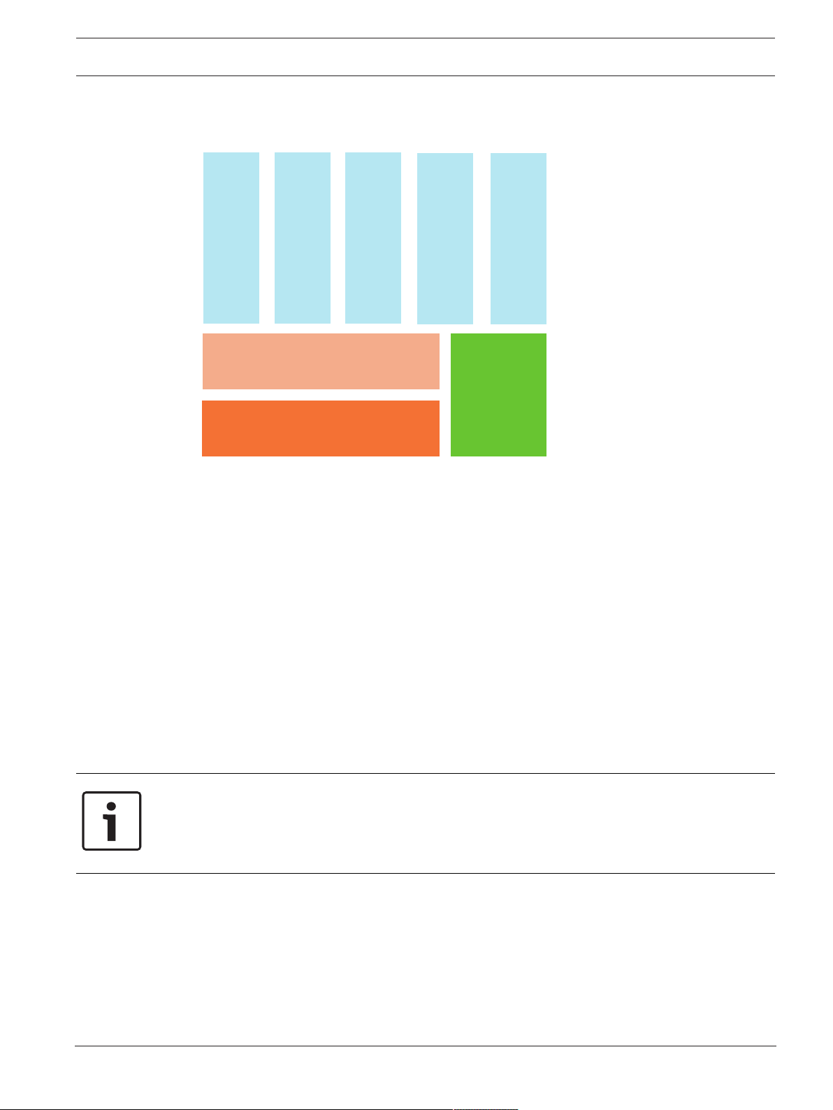
3.1 Networking layers
In the network, the Ethernet interface and IP protocols are used for different services. The
Ethernet interface can be disabled completely or its use disabled only for networking over
TCP/IP. Disabling may be necessary for networking over CAN.
Enabling services
– networking over TCP/IP
In FSP-5000-RPS, enable panel-to-panel communication in the Ethernet network
– OPC servers
Add an OPC server to the FSP-5000-RPS configuration
– Praesideo/PAVIRO connection
Add a Voice Alarm System to the FSP-5000-RPS configuration and configure virtual
triggers.
– Remote Services (Remote Connect, Remote Maintenance, Remote Alert)
Activate the relevant check box in FSP-5000-RPS
– Remote Connect and Remote Maintenance for Private Secure Network
Add remote access to the FSP-5000-RPS configuration and set up the remote access in
FSP-5000-RPS.
Notice!
Unintentionally data transfer
If the Ethernet interface of the panel controller is used only for communicating with an OPC
server or for Remote Services disable the panel communication over TCP/IP, in FSP-5000RPS. Otherwise fire data could be transferred over the Ethernet unintentionally.
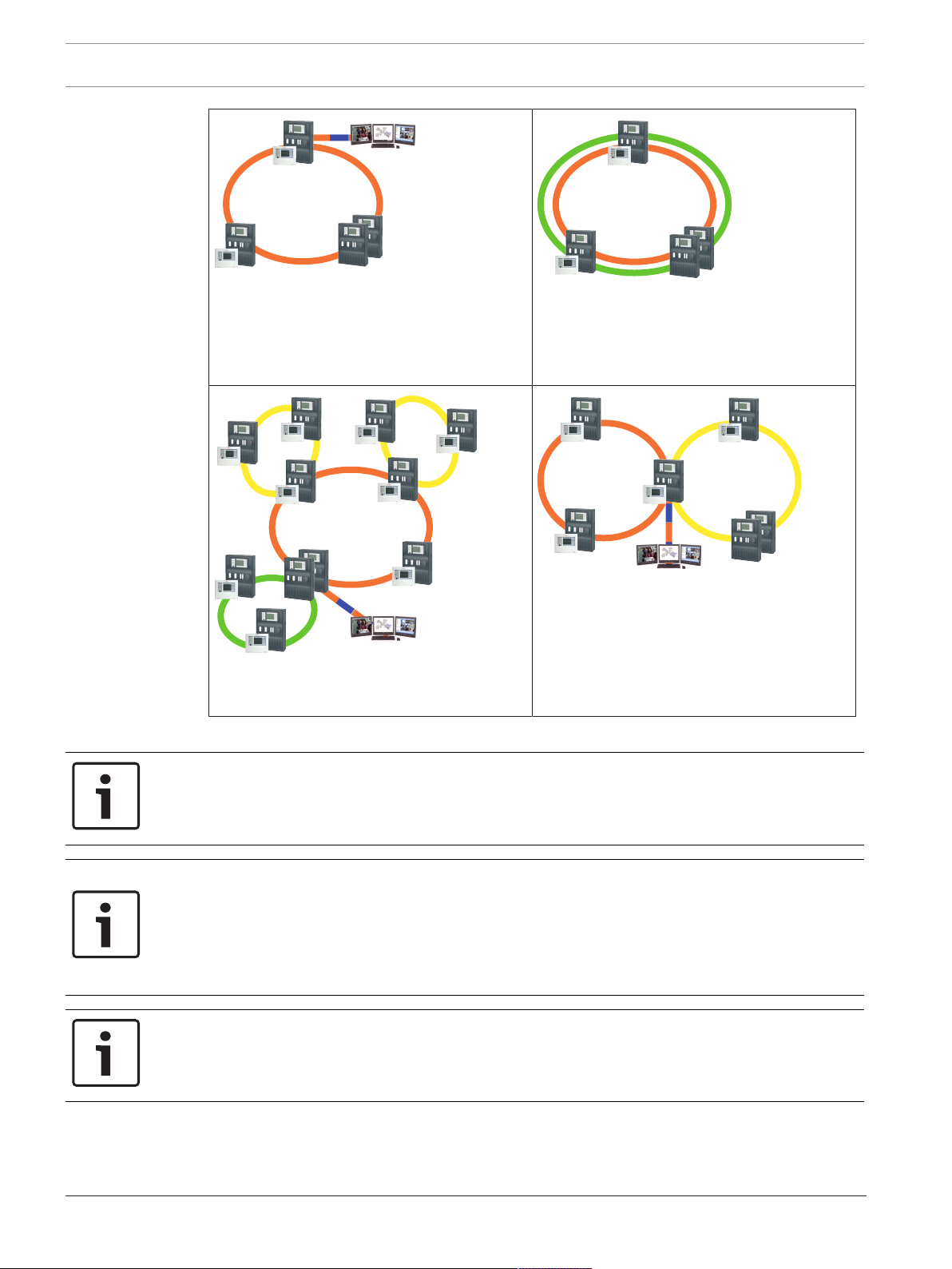
3.2 Topologies
Bosch Sicherheitssysteme GmbH Networking Guide 2017.12 | 5.7 | F.01U.247.450
To operate Ethernet or TCP/IP-based services, the Ethernet interfaces must be enabled and
the correct TCP/IP settings configured.
The following topologies are possible:
Page 8
8 en | Connecting FPA-5000 Modular Fire Panel
FPA/FMR
FPA-5000
FPA/FMR
FX
OPC-Server
FX
FPA/FMR
FPA-5000
CAN
FPA/FMR
FPA/FMR
FPA/FMR
FPA/FMR
FPA/FMR
FPA/FMR
FPA/FMR
FPA-5000
OPC-Server
FX
FX
FPA/FMR
FPA/FMR
FPA/FMR
FX
FPA-5000
FPA/FMR
FPA/FMR
FPA/FMR
FPA/FMR
OPC-Server
a
b
FX FX
Ethernet loop, page 12
Ethernet loop with OPC server, page 13
Ethernet/CAN double loop, page 15
Ethernet loop with OPC server to redundant
panel controller, page 14
Connecting Ethernet loops, page 18
Ethernet backbone with sub-loops (Ethernet/
CAN), page 16
The following settings, notes and restrictions apply to all topologies:
Notice!
For each panel, a maximum of 512 detection points may be connected according to EN54‑2.
If this number is exceeded, the panel must be designed redundantly. For technical reasons, a
maximum of 2048 detection points can then be connected.
Notice!
If the panel acts as an interface with a CAN sub-loop, this panel must then also be designed
redundantly according to EN54‑2 if more than 512 detection points are connected in the subloop.
This restriction does not apply in an Ethernet sub-loop, as the switches to connect the 2
loops perform the redundancy.
Notice!
The network used must meet the following minimum requirements:
Minimum throughput: 1 Mbps
Maximum latency: 250 ms
2017.12 | 5.7 | F.01U.247.450 Networking Guide Bosch Sicherheitssysteme GmbH
Page 9

Modular Fire Panel Connecting FPA-5000 | en 9
Notice!
The requirements of EN54‑13 for data transmission paths can only be met with fiber optic
cable connections for Ethernet.
Connections within a housing may be established with Ethernet cables.
Notice!
Switches and media converters in Ethernet networks must be installed in panel housings.
Installation outside of a panel housing is not compliant with EN54.
Notice!
To ensure that the network is set up in compliance with EN54, use only components that
have been approved for use in central fire alarm networks.
Notice!
Networks with more than 20 RSTP switches or a diameter greater than 20 require special
settings.
The standard setting for the IP configuration is only designed for networks with a maximum of
20 RSTP switches or a maximum network diameter of 20.
Make sure that the RSN assigned to the panel matches that in the programming software. The
latter is responsible for setting the last number of the IP address in the standard settings.
Activate "RSTP" as the redundancy protocol and adopt the default standard values.
Standard Ethernet settings of FPA
In the standard settings of the FPA, both the FSP‑5000‑RPS programming software and the
control unit adopt the set RSN as the last number of the IP address.
Notice!
Correct setting of the RSN on the panel controllers and in the FSP‑5000‑RPS programming
software is a requirement for a run-capable network.
Notice!
Use of the Ethernet redundancy must be activated separately in the panel controller.
– IP settings
– IP address 192.168.1.x
The last digit of the IP address in the standard settings is always identical to the RSN
set on the panel controller.
– Network screen 255.255.255.0
– Gateway 192.168.1.254
– Multicast address 239.192.0.1
– Port number 25001 - 25008 (only the first port can be set, 8 consecutive ports are
always used)
– RSTP parameters (redundancy settings)
– Bridge Priority 32768
– Hello Time 2
– Max. Age 20
Bosch Sicherheitssysteme GmbH Networking Guide 2017.12 | 5.7 | F.01U.247.450
Page 10
10 en | Connecting FPA-5000 Modular Fire Panel
– Forward Delay 15
Notice!
You can use the standard settings of the IP configuration with networks of up to 20 RSTP
switches.
In the case of networks with more than 20 RSTP switches, additional settings are required
according to the topology. In-depth knowledge of networks is required for this.
Settings for loops with more than 20 RSTP switches
If there are more than 20 RSTP switches in the network, then you must adjust the RSTP
settings on the panel controller and in the programming software. In-depth knowledge of
networks is required for this. The panel controllers and RSTP switches are regarded as RSTP
switches. Redundant panel controllers are not regarded as RSTP switches, as the switch
contained within these is not operated as an RSTP switch.
Parameters
– A maximum of 32 nodes can be used in a loop.
– The diameter of the network must not be greater than 32, see Network diameter, page
20.
– The Ethernet transmission sections outside of the panel housing must be designed as
fiber optic cable connections.
– Switches must not be used outside of panel housings.
– Media converters must not be used outside of panel housings.
– A maximum of one panel only and 3 FMR-5000 can be used in a network, in the case of
the FPA-1200.
Features
– The network is EN54-compliant.
– The network uses RSTP.
Additional information when using the OPC server
OPC servers in your network must be added to the RPS programming software.
You must perform the following settings in both the RPS software and on the OPC server:
– Network nodes
– Network group
– RSN
– IP Address
– Port
The OPC server uses port 25000 as standard.
Notice!
FSP-5000-RPS programming software:
Note that you must assign the OPC server to each network node from which statuses should
be transmitted.
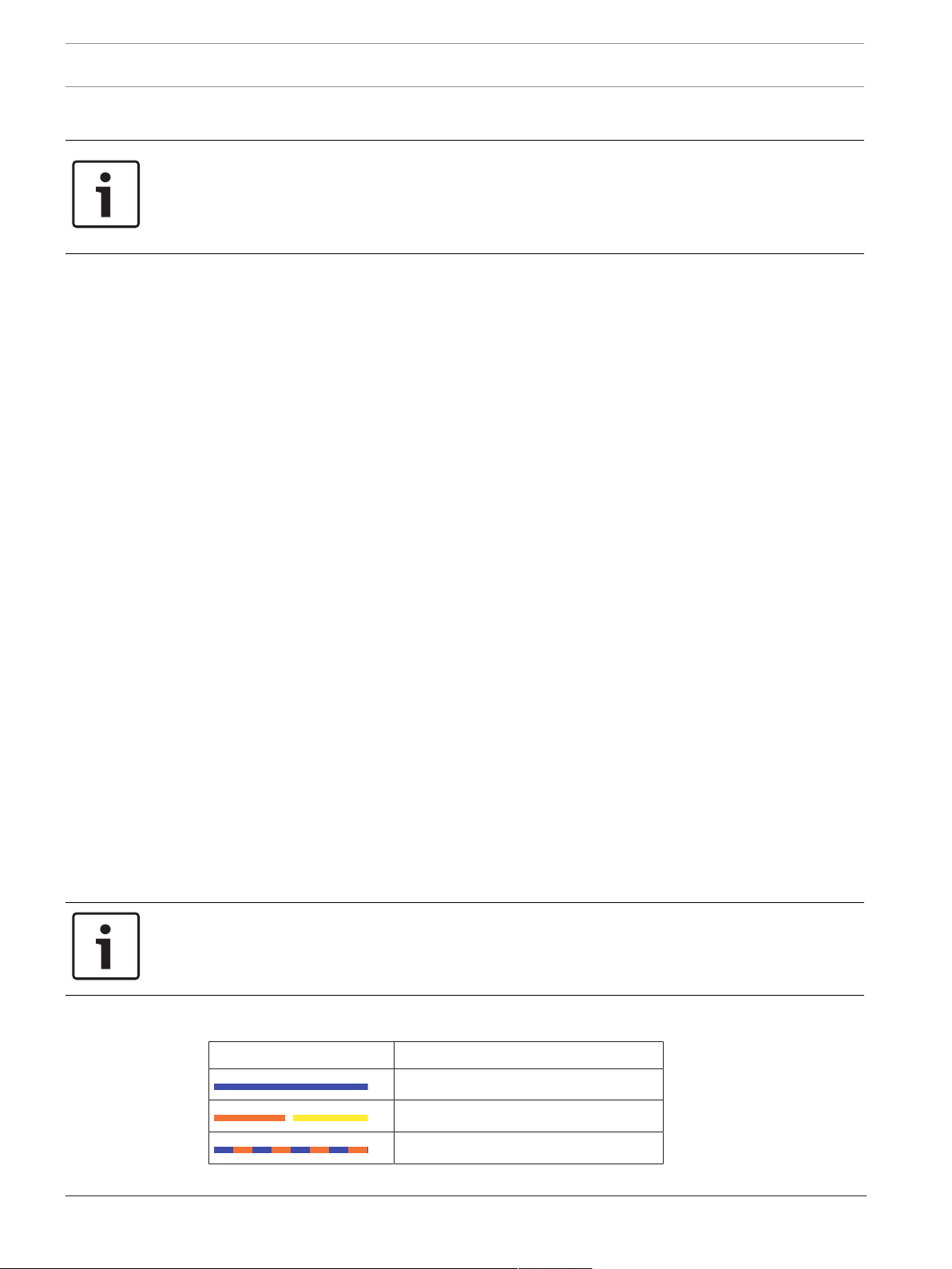
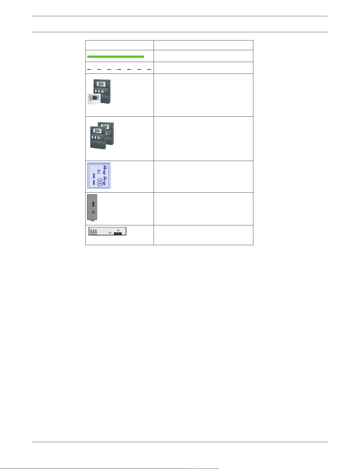
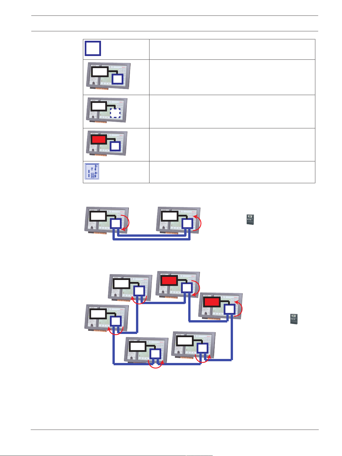
3.2.1 Key
Icon Description
TX Ethernet cable (copper)
FX Ethernet cable (fiber optic cable)
TX or FX Ethernet cable
2017.12 | 5.7 | F.01U.247.450 Networking Guide Bosch Sicherheitssysteme GmbH
Page 11
Modular Fire Panel Connecting FPA-5000 | en 11
FPA/FMR
FPA-5000
Icon Description
CAN bus
Housing
Panel/Remote Keypad
Redundant panel
Ethernet Switch (in general Ethernet
Switch MM)
Media converter
Secure Network Gateway for Remote
Services
Bosch Sicherheitssysteme GmbH Networking Guide 2017.12 | 5.7 | F.01U.247.450
Page 12

12 en | Connecting FPA-5000 Modular Fire Panel
FPA/FMR
FPA-5000
FPA/FMR
FX
FX
FX
FX FX
TX TX
TX TX
TX
3.2.2 Ethernet loop
For this configuration, the notes, settings, parameters and features specified in Topologies,
page 7 apply.
Figure3.1: Ethernet loop
Key, see Key, page 10
2017.12 | 5.7 | F.01U.247.450 Networking Guide Bosch Sicherheitssysteme GmbH
Page 13
Modular Fire Panel Connecting FPA-5000 | en 13
FPA/FMR
FPA-5000
FPA/FMR
OPC-Server
OPC-Server
FX
TX
FX
FX
TX
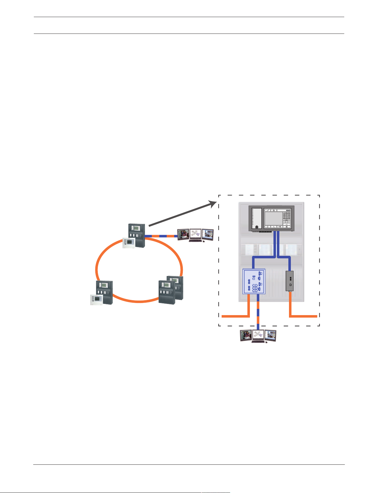
3.2.3 Ethernet loop with OPC server
For this configuration, the notes, settings, parameters and features specified in Topologies,
page 7 apply.
The information given here expands on Topologies, page 7.
Switch for connecting the OPC server must be programmed separately
Program the IP address and redundancy settings of the switch, see Settings on switch, page
38. As the switch is installed in the immediate vicinity (without intermediate space), the
power supply does not have to be designed redundantly and the fault outputs are therefore
not used.
Make sure that the RSTP settings in the panel controllers, RPS programming software and
switch are identical.
OPC server must be programmed separately
Program the IP address, network nodes, network group and RSN, see OPC servers, page 59.
The OPC server uses port 25000 as standard.
Make sure that the settings in the RPS programming software and OPC server are identical.
Parameters
– The OPC server may be connected via an Ethernet cable (copper) or fiber optic cable.
Figure3.2: Ethernet loop with OPC server
Key, see Key, page 10
Bosch Sicherheitssysteme GmbH Networking Guide 2017.12 | 5.7 | F.01U.247.450
Page 14

14 en | Connecting FPA-5000 Modular Fire Panel
FPA/FMR
FPA/FMR
OPC-Server
OPC-Server
FPA-5000
FX
FX FX
TX TX
3.2.4 Ethernet loop with OPC server to redundant panel controller
Figure3.3: Ethernet loop with OPC server to redundant panel
Key, see Key, page 10
2017.12 | 5.7 | F.01U.247.450 Networking Guide Bosch Sicherheitssysteme GmbH
Page 15
Modular Fire Panel Connecting FPA-5000 | en 15
FX
FX FX
FX
FX
TX TX
TX TX
TX
CAN
CAN
FPA/FMR
FPA-5000
CAN
CAN CAN
FPA/FMR
3.2.5 Ethernet/CAN double loop
For this configuration, the notes, settings, parameters and features specified in Topologies,
page 7 apply.
Figure3.4: Double loop of Ethernet and CAN
Key, see Key, page 10
Bosch Sicherheitssysteme GmbH Networking Guide 2017.12 | 5.7 | F.01U.247.450
Page 16

16 en | Connecting FPA-5000 Modular Fire Panel
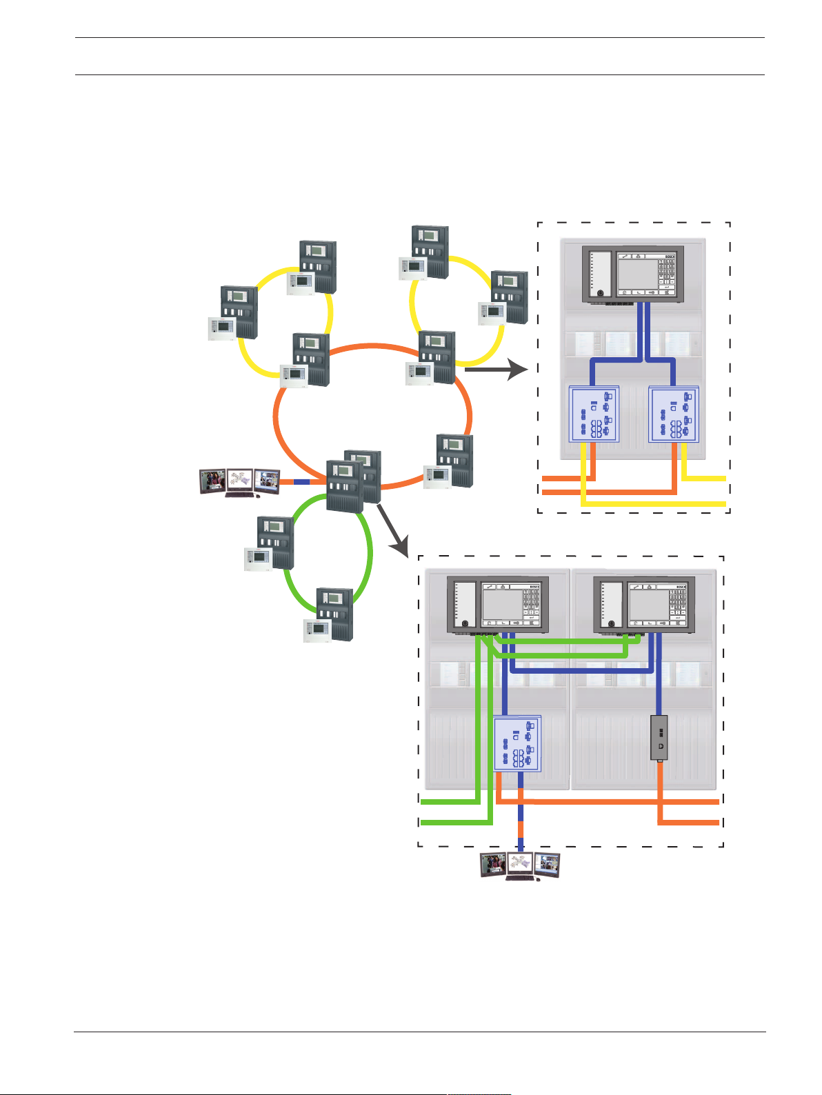
3.2.6 Ethernet backbone with sub-loops (Ethernet/CAN)
For this configuration, the notes, settings, parameters and features specified in Topologies,
page 7 apply.
The information given here expands on Topologies, page 7.
Notice!
This topology requires additional settings for all RSTP nodes in the backbone. More in-depth
knowledge of networks is therefore required.
Please note that with this topology you are required to determine the network diameter, see
Network diameter, page 20. Only RSTP devices are included in the network diameter, CANnetworked panels are disregarded.
Notice!
If the panel acts as an interface with a CAN sub-loop, this panel must then also be designed
redundantly according to EN54‑2 if more than 512 detection points are connected in the subloop.
This restriction does not apply in an Ethernet sub-loop, as the switches to connect the 2
loops perform the redundancy.
Additional settings
You must operate the central loop as the backbone. This must be networked via the Ethernet.
Notice!
For all panels and switches in the backbone, set a higher RSTP priority than in the sub-loops.
This ensures that the RSTP root bridge will always remain in the backbone, even in the event
of a fault.
The switches to connect the loops are part of the backbone!
Use a RSTP priority of 16384 in the backbone.
Notice!
The lower the set value, the higher the RSTP priority.
Settings for loops with more than 20 RSTP devices
Panel controllers connected via CAN are not regarded as RSTP switches when determining the
network diameter.
Switches for connecting the OPC server and the sub-loops must be programmed separately
Program the IP address and redundancy settings of the switches, see Settings on switch, page
38. For this topology, the fault outputs of the switch only have to be used if you have
designed the power supply for the switch redundantly or there is a switch-to-switch
connection, see Switch with power supply and fault relay.
Make sure that the RSTP settings in the panel controllers, RPS programming software and
switch are identical.
Notice!
Change the RSTP priority for the switches for connecting the loops, as they belong to the
backbone.
2017.12 | 5.7 | F.01U.247.450 Networking Guide Bosch Sicherheitssysteme GmbH
Page 17
Modular Fire Panel Connecting FPA-5000 | en 17
FPA/FMR
FPA/FMR
FPA/FMR
FPA/FMR
FPA/FMR
FPA/FMR
FPA-5000
OPC-Server
FX
FX
FPA/FMR
FPA/FMR
FPA/FMR
FX
OPC-Server
FX
FX
TX TX
TX
CAN
CAN
FX
FX
FX
FX
TX
TX
OPC server must be programmed separately
Program the IP address, network nodes, network group and RSN, see OPC servers, page 59.
The OPC server uses port 25000 as standard.
Make sure that the settings in the RPS programming software and OPC server are identical.
Parameters
– The OPC server may be connected via an Ethernet cable or fiber optic cable
Figure3.5: Ethernet backbone with sub-loops
Key, see Key, page 10
Bosch Sicherheitssysteme GmbH Networking Guide 2017.12 | 5.7 | F.01U.247.450
Page 18

18 en | Connecting FPA-5000 Modular Fire Panel
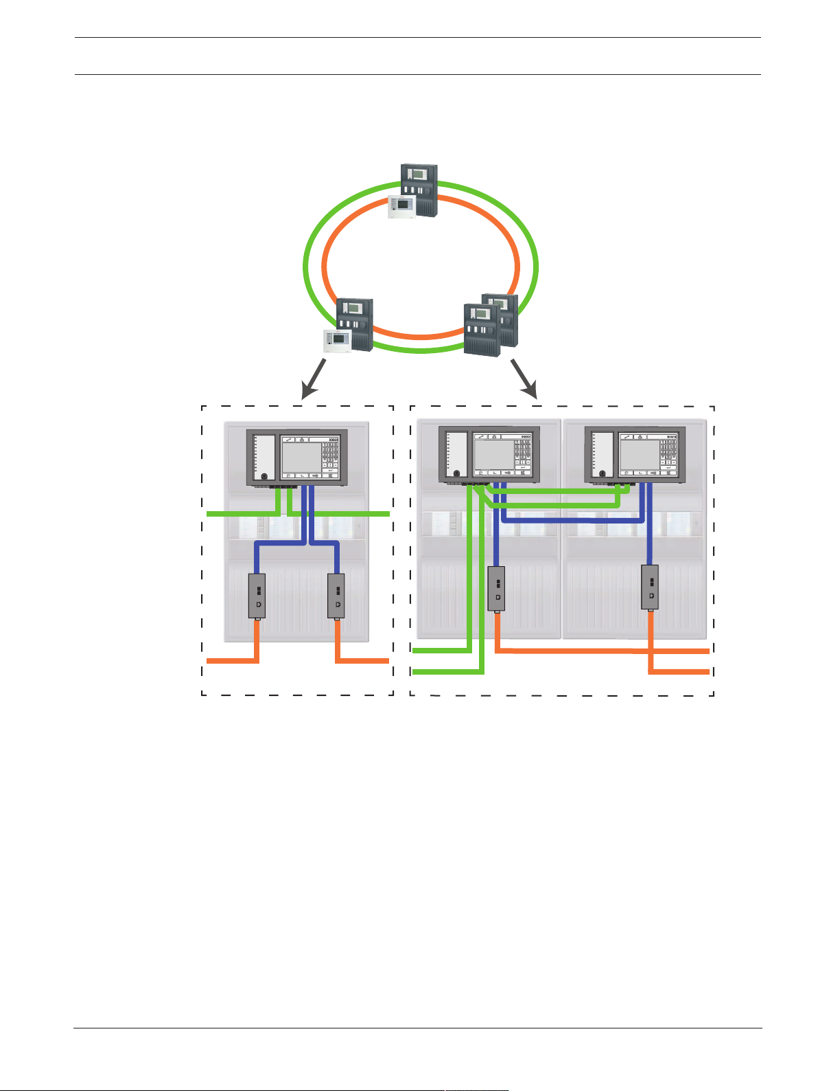
3.2.7 Connecting Ethernet loops
For this configuration, the notes, settings, parameters and features specified in Topologies,
page 7 apply.
The information given here expands on Topologies, page 7.
Notice!
This topology requires additional settings for all RSTP nodes in the backbone. More in-depth
knowledge of networks is therefore required.
Additional settings
This topology is a special instance of the Ethernet backbone with sub-loops, see Ethernet
backbone with sub-loops (Ethernet/CAN), page 16. You must operate one of the two loops as
the backbone.
Notice!
For all panels and switches in the backbone, set a higher RSTP priority than in the sub-loops.
This will ensure that the RSTP root bridge will always remain in the backbone, even in the
event of a fault.
The switches to connect the two loops are part of the backbone!
Use a RSTP priority of 16384 in the backbone.
Notice!
The lower the set value, the higher the RSTP priority.
Switches for connecting the OPC server and the second loop must be programmed
separately
Program the IP address and redundancy settings of the switch, see Settings on switch, page
38. For this topology, the fault outputs of the switch only have to be used if you have
designed the power supply for the switch redundantly, for connections see Switch with power
supply and fault relay.
Make sure that the RSTP settings in the panel controllers, RPS programming software and
switch are identical.
Change the RSTP priority for the switches for connecting the two loops, as they belong to the
backbone.
OPC server must be programmed separately
Program the IP address, network nodes, network group and RSN, see OPC servers, page 59.
The OPC server uses port 25000 as standard.
Make sure that the settings in the RPS programming software and OPC server are identical.
Parameters
– The OPC server may be connected via an Ethernet cable (copper) or fiber optic cable
In these examples, loop a is the backbone. Loop b is the sub-loop.
2017.12 | 5.7 | F.01U.247.450 Networking Guide Bosch Sicherheitssysteme GmbH
Page 19

Modular Fire Panel Connecting FPA-5000 | en 19
FPA-5000
FPA/FMR
FPA/FMR
FPA/FMR
OPC-Server
a
b
FX
FX
OPC-Server
a
b
TX
FX
FX
FX
FX
TX
FPA/FMR
FPA/FMR
OPC-Server
FPA/FMR
FPA/FMR
FPA/FMR
OPC-Server
FPA-5000
a
a b
b
FX
TX
FX
FX
FX
TX
FX FX
Figure3.6: Connecting Ethernet loop via a non-redundant panel
Figure3.7: Connecting Ethernet loop via a redundant panel
Key, see Key, page 10
Bosch Sicherheitssysteme GmbH Networking Guide 2017.12 | 5.7 | F.01U.247.450
Page 20

20 en | Connecting FPA-5000 Modular Fire Panel
CPU
3.3 Ethernet network
In the network, the Ethernet network connections are monitored continuously. If a connection
has been severed, then the interruption is detected. Repaired connections are also detected.
MAC addresses
Each panel controller has 3 MAC addresses.
– MAC address for the host
– MAC address for network connection 1 (Eth 1)
– MAC address for network connection 2 (Eth 2)
The network diagnosis of the panel always shows you the MAC address of the hosts
connected via the network.
3.3.1 Protocols
SNMP
SNMP is used to monitor and control network components. To this end, parameters of
network nodes can be read out or modified. For this you require the appropriate network
management software (e.g. Hirschmann HiVision).
Notice!
The network uses the following SNMP password: PUBLIC
LLDP
LLDP is a basic protocol standardized by the IEEE. It is used to share network information
between neighboring devices. This information is
– provided as part of the SNMP data
– displayed via the panel controller as part of the network diagnostic data
RSTP
RSTP is a network protocol standardized by the IEEE. RSTP ensures that there are no loops in
networks. Redundant paths are detected in the network, deactivated and activated when
necessary (failure of a connection).
The protocol is used for exactly this purpose in the network.
A change to the bus topology following the failure of a connection is automatically canceled
once it has been repaired.
3.3.2 Network diameter
The network diameter of FPA-RSTP Ethernet networks must not be greater than 32.
Definition
The diameter of a network corresponds to the number of RSTP switches on the longest
possible section without loops between any 2 end points in the network.
The following must be taken into account in relation to a FPA-RSTP Ethernet network:
– Each MPC contains an end point and an internal RSTP switch.
– A combination of MPC and redundant MPC counts as just one RSTP switch.
– Media converters are not regarded as RSTP switches.
– CAN connections may not be included in the longest possible section.
– OPC servers are not taken into account with respect to the diameter.
Key
Central processor in the panel controller or in the remote
keypad.
2017.12 | 5.7 | F.01U.247.450 Networking Guide Bosch Sicherheitssysteme GmbH
Page 21
Modular Fire Panel Connecting FPA-5000 | en 21
S
CPU
S
CPU
S
CPU
S
1
2
Ø = 2 =
#
MPC MPC
CPU
CPU
CPU
1
2
CPU
CPU
CPU
3
4
5
6
Ø = 6 =
#
MPC
MPC
MPC
MPC
MPC
MPC
Internal RSTP switch in the panel controller or in the remote
keypad.
Panel controller or remote keypad with central processor and
internal RSTP switch.
Redundant panel controller with central processor and internal
RSTP switch.
Panel controller/remote keypad
Starting point/end point for determining the diameter in the
examples.
Ethernet Switch (in general Ethernet Switch MM) as external
RSTP switch
2 connected panels form the smallest possible loop. The diameter of this network is equal to
2, as the internal switches are located between the end points.
Bosch Sicherheitssysteme GmbH Networking Guide 2017.12 | 5.7 | F.01U.247.450
Figure3.8: Network diameter of a loop with 2 panels
In a panel loop without external switches, the diameter of the network corresponds to the
number of installed panels.
Figure3.9: Network diameter of a loop with 6 panels
If a backbone and sub-loops are connected to each other via RSTP switches not integrated
into the panel controller, then the RSTP switches must also be taken into account.
Page 22

22 en | Connecting FPA-5000 Modular Fire Panel
3
7
910
11
2
4
12
14
15
16
Ø = 18
# = 14
17
6
1
5
8
13
18
MPC MPC
MPC
MPC MPC
MPC
MPC
MPC
MPC
MPC
MPC
MPC
MPC
MPC
MPC
MPC
Figure3.10: Network diameter of a backbone with sub-loops
The figure shows that the longest path must always be found for the diameter.
3.3.3 Cables used
Use only the following cables for networking:
– Ethernet cable
Ethernet patch cable, shielded, CAT5e or better.
Note the minimum bending radii specified in the cable specification.
– Fiber optic cable
Multi-mode: fiber optic Ethernet patch cable, duplex I‑VH2G 50/125μ or duplex I‑VH2G
62.5/125μ, SC plug.
Single mode: fiber optic Ethernet patch cable, duplex I‑VH2E 9/125μ, SC plug.
Note the minimum bending radii specified in the cable specification.
2017.12 | 5.7 | F.01U.247.450 Networking Guide Bosch Sicherheitssysteme GmbH
Page 23

Modular Fire Panel Connecting FPA-5000 | en 23
3.3.4 Creating an Ethernet network
There are several procedures for creating a network of fire alarm control panels. The 2
procedures described below differ in the size of the networks and the number of installation
and configuration tasks carried out alongside each other.
Procedure for smaller projects
This procedure is suitable for projects involving only a small number of engineers working on
the installation of the fire alarm system concurrently.
1. Plan out the network.
2. Create the network in FSP‑5000‑RPS and configure the network settings.
3. Print the network information out for safe keeping, or store the information on the
laptop.
4. Install the control panels and network cables and connect them to a network.
5. Configure the network settings for the individual control panels directly at the control
unit as per the printout.
6. Reset each of the control panels in the network in order to activate the network
configuration.
7. Connect your computer with the FSP‑5000‑RPS programming software to a control panel
in the network. Load this configuration to all other control panels across the network via
this control panel. Redundant panels use the main panel configuration.
8. Carry out a reset in order to reset the pending error messages. Rectify any errors.
Configure the network settings on the control panels first. This gives you the advantage that
you can program the other control panels in the network from one control panel.
Procedure for medium-sized and large projects
This procedure is suitable for projects involving a number of tasks carried out concurrently by
several teams. As many tasks performed during installation and configuration involve
restarting the fire alarm control panel, the network is not started up in this procedure until a
later stage.
1. Plan out the network.
2. Produce a configuration of the network without peripherals with FSP‑5000‑RPS.
3. Print the network information out for safe keeping, or store the information on the
laptop.
4. Install the network cables and check individual sections or loops.
5. Install the panels and commission them as stand-alone panels.
6. Install the peripherals in the panels.
7. Configure each of the panels with RPS.
8. Ensure that the individual panels are working correctly.
9. Commission the individual loops of the network one after the other, according to the
topology.
Start with the backbone.
– Produce a configuration for the backbone in RPS. Import all of the necessary panel
configurations. Configure the network settings and print them out.
– Connect all panels to a network.
– Configure the network settings for the individual control panels directly at the panel
controller as per the printout.
– Reset each of the control panels in order to load the network configuration.
– Ping the neighboring panels in order to check the network.
– Commission the entire backbone and rectify any errors.
Commission the sub-loops as per the example of the backbone.
Bosch Sicherheitssysteme GmbH Networking Guide 2017.12 | 5.7 | F.01U.247.450
Page 24

24 en | Connecting FPA-5000 Modular Fire Panel
3.3.5 Extension of existing networks
In order to ensure fault-free communication between all connected panels, all panels must
have the same firmware version. Remind for redundand panels, that a firmware update is
possible for the main panel solely. Switch the redundant panel to main panel to perform the
firmware update for this panel.
3.4 CAN network
Up to 32panel controllers, remote keypads and OPC servers can be combined to form a
network.
Depending on the intended application, different panel controllers and remote keypads can be
divided into groups and defined as network nodes or local nodes. As a rule, within any given
group, only the status of control panels within the defined group can be displayed. The status
of all control panels can be displayed and/or processed from network nodes, irrespective of
the group to which the panels belong.
The panels can be networked redundantly as a loop via CAN1 and CAN2.
FOC networking
In a loop, panels can be connected using fiber optic cables via CAN/FOC adapters.
The CAN/FOC converters from EKS enable distances of up to 15km between two nodes to be
overcome in a network (depending on the converter type and the fiber optic cable used). The
following converters are available (PzPCANFOC system/MM):
– DL-CAN/1x13-MM-ST system
– DL-CAN/1x13-MM-SC system
– DL-CAN/1x13-SM-ST system
– DL-CAN/1x13-SM-SC system
Loop topology
– In loop topology, the CAN cable is always routed from a CAN1 terminal to a CAN2
terminal [CAN1 ⇒ CAN2].
A CAN segment thus consists of two bus users. The cable length depends on the cable
cross-section.
– Due to the maximum of 32nodes and the maximum cable length of 1000m between
nodes, a system can be installed with a total cable length of 32km.
Networking of panels and remote keypads
The table below shows the options for networking panels/remote keypads depending on the
network topology.
Topology FPA-1200 FPA-5000
Standalone panel Possible Possible
Standalone panel,
redundant
Loop 1 FPA-1200 + max. 3 FMR‑5000 Max. 32 FPA‑5000/FMR‑5000
Loop with redundant
panel
Not possible Possible
Not possible Max. 32 FPA‑5000/FMR‑5000 +
redundant FPA-5000
Refer to the limits determined by the network topology.
As the FPA-1200 is not operated as the redundant panel, DIP 6 on FPA-1200-MPC is not functional!
2017.12 | 5.7 | F.01U.247.450 Networking Guide Bosch Sicherheitssysteme GmbH
Page 25

Modular Fire Panel Connecting FPA-5000 | en 25
Limits in network
The number of panels and remote keypads that can be networked depends on the choice of
network topology.
Networked panels and remote keypads are known as "nodes".
– The number of detection points in a network is limited to 32,768.
– The number of detection points per panel operated in a network is limited to 2048.
– The number of nodes per system depends on the type of topology.
A node is either an MPC Panel Controller or an FMR-5000 Remote Keypad.
– The number of nodes in loop topology is limited to 32.
– The number of nodes per CAN segment is limited to eight.
A CAN segment is the physical connection of a CAN line.
– Up to 3 remote keypads to a specific panel can be directly assigned to the network using
the FSP-5000-RPS Programming Software.
The cabling between nodes and the maximum permissible cable length is also determined by
the choice of topology.
Cable type for networking
The CAN connection is a two-wire connection (CAN‑H and CAN‑L). A three-wire connection
(CAN‑H, CAN‑L and CAN‑GND) may be necessary in exceptional cases, e.g. with a high EMC
load or a significant difference in grounding potential. The shield wire of the CAN cable is only
connected to the metal housing of the panel on one side.
Cable length for networking
The maximum permitted cable length depends on the loop resistance of the cable used and on
the number of communicating.
Example: The J-Y (St) Y 2 x 2 x 0,8 mm red fire detector cable enables two nodes with a
maximum distance of around 800 m to be connected.
Notice!
The distance between two nodes in loop topology can be determined by reading off the value
at two nodes in the diagram.
Bosch Sicherheitssysteme GmbH Networking Guide 2017.12 | 5.7 | F.01U.247.450
Page 26

26 en | Connecting FPA-5000 Modular Fire Panel
Figure3.11: CAN network: Achievable cable length, depending on the number of nodes and the cable
resistance
L = cable length in meters
N = number of nodes
3.4.1 Creating a CAN network
This procedure is suitable for projects involving only a small number of engineers working on
the installation of the fire alarm system concurrently.
Procedure
1. Plan out the network.
2. Create the network in FSP‑5000‑RPS.
3. Print the network information out for safe keeping, or store the information on the
laptop.
4. Install the control panels and connect them with CAN cables to a network.
5. Connect your computer with the FSP‑5000‑RPS programming software to a control panel
in the network. Load this configuration to all other control panels across the network via
this control panel. Redundant panels use the configuration of the main panel.
6. Carry out a reset in order to reset the pending error messages. Rectify any errors.
3.4.2 Extension of existing networks
In order to ensure fault-free communication between all connected panels, all panels must
have the same firmware version. Remind for redundand panels, that a firmware update is
possible for the main panel solely. Switch the redundant panel to main panel to perform the
firmware update for this panel.
2017.12 | 5.7 | F.01U.247.450 Networking Guide Bosch Sicherheitssysteme GmbH
Page 27

Modular Fire Panel Connecting FPA-5000 | en 27
FPA/FMR
FPA/FMR
FSP-
5000--
RPS
Remote
Connect
TX
FX
TX
FX
3.5 Remote Services
The following services belong to Remote Services:
– Remote Connect
– Remote Alert
– Remote Maintenance
Prerequisite for Remote Alert and Remote Maintenance is Remote Connect.
3.5.1 Remote Connect
Remote Connect provides a trusted and secure internet connection, which enables remote
access to a panel via FSP-5000-RPS. Remote Connect is the basis for all Remote Services. For
Remote Connect use the Secure Network Gateway (CTN: C1500).
In case of a panel network, one panel of the panel network has to be connected to a Secure
Network Gateway. Exclusively this connection, needs to be a dedicated Ethernet connection.
Notice!
While Remote Connect supports connection to a panel network via Ethernet or CAN, Remote
Alert and Remote Maintenance functionality is only supported when an Ethernet connection is
provided and configured for service usage.
Remote Connect has to be enabled in the FSP-5000-RPS configuration of this panel.
The following topology shows panel controllers connected via Ethernet where a Secure
Network Gateway is connected to the network via a Ethernet Switch (in general Ethernet
Switch MM).
Figure3.12: Remote Connect in an Ethernet loop
Bosch Sicherheitssysteme GmbH Networking Guide 2017.12 | 5.7 | F.01U.247.450
Page 28

28 en | Connecting FPA-5000 Modular Fire Panel
FPA/FMR
FPA/FMR
CAN
FPA/FMR
FSP5000--
RPS
Remote
Connect
Notice!
Use only media converters to connect the panel via FX.
To prevent sending EN 54-2 relevant multicast traffic to the router, use the Ethernet Switch (in
general Ethernet Switch MM BPA-ESWEX-RSR20) approved with panel version 2.8. Activate
IGMP snooping of the Ethernet Switch, see Activating IGMP snooping, page 41.
Notice!
The internet router (or the company network which provides internet access) as well as the
Secure Network Gateway must provide separated sub-networks. Panels of the panel network
may not be placed in the sub-network of the internet router. Also overlapping of the subnetworks is not possible.
In case of overlapping sub-networks you have to separate the sub-networks by changing the
IP addresses on panel network side.
Additionally you have to propagate the changes to the Secure Network Gateway. To do so,
launch the web interface via a web browser:
- Address: https://192.168.1.254
- User name: bosch
- Password: ipti83
Under Configuration -> Network (LAN) you can change the IP address. Consider, that the
Default gateway: address in the panel controller configuration must match the IP address of
the Secure Network Gateway.
The following topology shows a CAN network where a Secure Network Gateway is connected
to the network via Ethernet port.
Figure3.13: Remote Connect in a CAN loop
For connecting the Secure Network Gateway to a redundant panel controller you can use the
following topology.
2017.12 | 5.7 | F.01U.247.450 Networking Guide Bosch Sicherheitssysteme GmbH
Page 29

Modular Fire Panel Connecting FPA-5000 | en 29
ETH1
ETH1
TX TX
FSP-
5000--
RPS
Remote
Connect
FPA/FMR
Remote
Maintenance
3.5.2 Remote Alert
Through Remote Alert, a panel pushes relevant status information to the Remote Portal.
Remote Alert analyzes these data. In case of an unexpected event, the Remote Portal notifies
the user via SMS and/or E-Mail about the received alerts.
3.5.3 Remote Maintenance
Remote Maintenance offers the possibility to remotely monitor certain parameters of various
security items connected to a fire panel. Via the Remote Portal, you can conduct walk tests.
Figure3.14: Remote Maintenance
Notice!
Ethernet connections used only to transfer Remote Maintenance data may be designed both
as Ethernet cables and fiber optic connections. Note the permitted maximum cable lengths.
Notice!
The connection used for Remote Maintenance must be non-interacting.
Bosch Sicherheitssysteme GmbH Networking Guide 2017.12 | 5.7 | F.01U.247.450
Page 30

30 en | Connecting FPA-5000 Modular Fire Panel
FPA/FMR
FPA/FMR
FX
FPA/FMR
FX
TX
FX
TX
Remote
Maintenance
!
Notice!
Note that Remote Maintenance data is transferred in unencrypted form.
Notice!
Use only media converters to connect the panel via FX.
Figure3.15: Remote Maintenance
When using Remote Maintenance with Ethernet networks, one panel in the network must be
connected to the router for data transfer purposes. All collected data is transfered from the
network via this connection.
Remote Maintenance for Remote Portal
Remote Maintenance is by default configured for Remote Portal: Remote Maintenance collects
data of relevant LSN devices and functional modules and sends them to the Remote Portal
where they are analyzed and visualized for maintenance activities.
Remote Maintenance for Private Secure Network
Remote Maintenance can also be configured for Private Secure Network: Collected data will
be sent to a central management server system (CMS).
Caution!
Remote Maintenance for Private Secure Network requires a secure IP connection. For this
reason with Remote Maintenance for Private Secure Network an IP network is provided,
which is based on DSL with an optional wireless access on the panel side. Remote
Maintenance for Private Secure Network is only available in Germany with a service
agreement with Bosch ST-IE.
2017.12 | 5.7 | F.01U.247.450 Networking Guide Bosch Sicherheitssysteme GmbH
Page 31

Modular Fire Panel Connecting FPA-5000 | en 31
FPA/FMR
FPA/FMR
FX
FPA/FMR
FX
TX
FX
TX
Remote
Maintenance via
Private Secure
Network
Service
Center
Figure3.16: Remote Maintenance for Private Secure Network
For Remote Maintenance, you must enter the server IP address and port of the Remote
Maintenance system server in the FSP-5000-RPS programming software.
Assign a unique Panel Network ID to the network.
Switch for connecting the CMS must be programmed separately
Program the IP address and redundancy settings of the switch, see Settings on switch, page
38. As the switch is installed in the immediate vicinity (without intermediate space), the
power supply does not have to be designed redundantly and the fault outputs are therefore
not used.
Make sure that the RSTP settings in the panel controllers, FSP-5000-RPS programming
software and switch are identical.
3.6 Voice alarm systems
Notice!
If an MPC-xxxx-B panel controller shall be used for the direct connection to a Praesideo/
PAVIRO system a cross-over patch cable is required as neither Praesideo/PAVIRO nor the
MPC-xxxx-B supports Auto-MDI(X).
The following topology shows panel controllers connected via Ethernet where the Praesideo/
PAVIRO system is integrated in the panel loop using an Ethernet interface.
Bosch Sicherheitssysteme GmbH Networking Guide 2017.12 | 5.7 | F.01U.247.450
Page 32

32 en | Connecting FPA-5000 Modular Fire Panel
FPA/FMR
FPA/FMR
FXFX
FPA/FMR
Praesideo/
PAVIRO
Praesideo/
PAVIRO
TX
FPA/FMR
FPA/FMR
FPA/FMR
FPA
FX
FX
TX
CAN
CAN
TX
Praesideo/
PAVIRO
FXFX
Praesideo/
PAVIRO
TX
Figure3.17: Ethernet loop with Praesideo/PAVIRO
Use the Ethernet Switch (in general Ethernet Switch MM BPA-ESWEX-RSR20) approved with
panel firmware version 2.8.
To prevent sending EN 54-2 relevant multicast traffic to the Praesideo/PAVIRO system,
activate IGMP snooping of the Ethernet Switch MM, see Activating IGMP snooping, page 41.
Notice!
If an MPC-xxxx-B panel controller shall be used for the direct connection to a Praesideo/
PAVIRO system a cross-over patch cable is required as neither Praesideo/PAVIRO nor the
MPC-xxxx-B supports Auto-MDI(X).
In every panel controller of a CAN network you can connect one Praesideo/PAVIRO system
using an Ethernet interface. The following topology shows panel controllers connected via
CAN where the Praesideo/PAVIRO system is connected to one panel controller using an
Ethernet interface.
Figure3.18: Praesideo/PAVIRO connection to a CAN network
2017.12 | 5.7 | F.01U.247.450 Networking Guide Bosch Sicherheitssysteme GmbH
Page 33

Modular Fire Panel Connecting FPA-5000 | en 33
Notice!
Because CAN network traffic shall not be transferred through the Ethernet connection, you
must switch off networking over IP in the FSP-5000-RPS programming software.
If this is not switched off, the network will not be compliant with EN 54.
3.7 UGM-2040 networks
The topologies to be installed and the network settings to be programmed can be obtained
from your UGM 2040 BMA planner. See also the UGM 2040 BMA Anschaltehandbuch.
Bosch Sicherheitssysteme GmbH Networking Guide 2017.12 | 5.7 | F.01U.247.450
Page 34

34 en | Installation Modular Fire Panel
6x KB40 x 12 mm
FBH 0000 A
(FHS 0000 A)
4 Installation
Checklist
Before starting with the installation of the network, please review all of the points set out
below.
– Ethernet and CAN
– The requisite line lengths of the Ethernet TX, Ethernet FX and CAN TX and CAN FX
cables are less than their maximum length.
– The entire peripherals and their cabling in the individual panels are planned.
– Network planning
– All IP addresses and network settings for the individual panels and additional
network components are planned and at your disposal.
– An overview of the additional components to be installed, such as switches and
media converters, and their cabling with neighboring panels is at your disposal.
– An overview of the network topology to be installed is at your disposal.
– All network redundancy settings have been planned and are at your disposal.
Danger!
Laser light.
Do not look directly into the beam with the naked eye or with visual instruments of any kind
(e.g. magnifying glass, microscope). Failure to observe this notice poses a danger to the eyes
at a distance of less than 100 mm. The light emerges at the visual terminals or at the end of
the fiber optic cables connected to these. CLASS 2M light-emitting diode, wavelength
650nm, output < 2 mW, in accordance with DINEN60825‑1:2003‑10.
4.1 Installing media converters in the mounting frame
Install the media converters in the corresponding FPM‑5000‑KMC bracket
Figure4.1: Installation of FPM‑5000‑KMC bracket in mounting frame
2017.12 | 5.7 | F.01U.247.450 Networking Guide Bosch Sicherheitssysteme GmbH
Page 35

Modular Fire Panel Installation | en 35
M
C
M
C
click
M
C
M
C
3x M4 x 5 mm
PSS 0002 A
USF 0000 A
Figure4.2: Installation of media converters in the FPM‑5000‑KMC bracket
4.2 Installing media converters in PSS0002A/USF0000A
Install the media converters in the FPM‑5000‑KES. bracket
In the case of the USF0000A you need to remove the installed mounting plate.
Figure4.3: Installation of FPM‑5000‑KES bracket in housings
Bosch Sicherheitssysteme GmbH Networking Guide 2017.12 | 5.7 | F.01U.247.450
Page 36

36 en | Installation Modular Fire Panel
click
M
C
M
C
Figure4.4: Installation of media converters in the FPM‑5000‑KES bracket
4.3 Settings on media converter
Only a few steps are required to use the media converter:
– Set the DIP switches.
– Connect the media converter to the FX network cables and CAT5e network cables.
– Supply the media converter with power via the internal BCM battery controller module.
Notice!
The media converters are only supplied with power via power supply terminal 1.
The error LED on the media converter is therefore continuously lit. However, this does not
affect the functionality of the device.
Notice!
Use only the following cables for networking:
Ethernet cable
Ethernet patch cable, shielded, CAT5e or better.
Note the minimum bending radii specified in the cable specification.
Fiber optic cable
Multi-mode: fiber optic Ethernet patch cable, duplex I‑VH2G 50/125μ or duplex I‑VH2G
62.5/125μ, SC plug.
Single mode: fiber optic Ethernet patch cable, duplex I-VH2E 9/125μ
Note the minimum bending radii specified in the cable specification.
Notice!
Refer to the installation guides for the mounting kits for information on how to install a media
converter in the housing of a panel: FPM 5000 KMC (F.01U.266.845) FPM‑5000‑KES
(F.01U.266.844)
2017.12 | 5.7 | F.01U.247.450 Networking Guide Bosch Sicherheitssysteme GmbH
Page 37

Modular Fire Panel Installation | en 37
1
0
Notice!
The maximum transmission section for multimode media converters via FX is 2000m.
The maximum transmission section for single mode media converters via FX is 40km.
Using the DIP switches, configure the media converter as shown in the following figure.
Notice!
Only change the DIP switch settings on media converters when they are de-energized.
DIP switch number Setting
1 Link Fault Pass-Through activated
2 Ethernet: automatic mode
3 Ethernet: 100 MBit
4 Ethernet: fully duplex
5 Fiber optic cable: fully duplex
6 Link down: off
4.4 Installing switches in PSS0002A/USF0000A
Notice!
If you are using switches in the network, these must be included in the configuration in the
FSP-5000-RPS programming software.
Notice!
Do not use the supplied network cable to connect the switches, as it is not shielded.
Use an Ethernet patch cable, shielded, CAT5e or better.
Install the switches in the corresponding FPM‑5000‑KES. bracket
Bosch Sicherheitssysteme GmbH Networking Guide 2017.12 | 5.7 | F.01U.247.450
Page 38

38 en | Installation Modular Fire Panel
3x M4 x 5 mm
PSS 0002 A
USF 0000 A
click
Figure4.5: Installation of FPM‑5000‑KES bracket in housings
Figure4.6: Installation of switches in the FPM‑5000‑KES bracket
4.5 Settings on switch
In order to be able to use the switches in the network, you need to program them.
Connect your laptop to the network and use the HiDiscovery software supplied by the
manufacturer to carry out the initial programming of the switches. Using this software, search
for the switches in the network. Double-click on a switch to select it and assign an IP address
to it.
Following the initial programming of the IP address, you can use a web browser to call up the
configuration user interface for the switch.
2017.12 | 5.7 | F.01U.247.450 Networking Guide Bosch Sicherheitssysteme GmbH
Page 39

Modular Fire Panel Installation | en 39
Notice!
Refer to the manufacturer's user guide for an exact description of the installation and
configuration of the switches. Access data:
User: admin
Password: private
Use a browser to call up the configuration user interface for the switches.
You must perform the following settings in the switch:
– Assign IP address, page 39,
– Program redundancy settings, page 39.
Furthermore, optional settings e.g.:
– Programming the fault relay, page 40,
– Programming connection monitoring, page 41,
– Activating IGMP snooping, page 41.
4.5.1 Assign IP address
Notice!
Practical tip:
In the device part of IP addresses, use numbers greater than 200 (xxx.xxx.xxx.200) for
switches, if your network configuration allows this. This will give you a clearer separation
between the IP addresses of the panels and those of the switches.
Example:
Switch 192.168.1.201 is assigned to the panel with the IP address 192.168.1.1.
Notice!
Please refer to the following manufacturer documents for an exact description of the
installation and configuration of the switches:
Installation user guide
Web-based interface reference guide
Use a browser to go to the configuration user interface for the switch.
In the Basic Settings -> Network menu, set the following values depending on the topology
chosen:
– Mode: local
– IP address: the required IP address, e.g. 192.168.1.201
– Network screen: the required network screen, e.g. 255.255.255.0
– Gateway: the required gateway, e.g. 0.0.0.0 if no gateway is required
Click on Write.
Notice!
The settings in the individual menu items in the switch configuration take effect after clicking
on Write.
The settings are only saved permanently, i.e. so that they are retained even after the device is
restarted, if under Basic Settings -> Load/Save in the Save field you select the item On the
device and click on the Save button.
4.5.2 Program redundancy settings
As the FPA panel networks use RSTP as the redundancy protocol, you must activate and
program the protocol in the configuration user interface:
In the Redundancy -> Spanning Tree -> Global menu, set the following values:
Bosch Sicherheitssysteme GmbH Networking Guide 2017.12 | 5.7 | F.01U.247.450
Page 40

40 en | Installation Modular Fire Panel
– Function: On
– Protocol version: RSTP
– Protocol configuration: Same settings as for the panel controllers
Click on Write.
Notice!
The settings in the individual menu items in the switch configuration take effect after clicking
on Write.
The settings are only saved permanently, i.e. so that they are retained even after the device is
restarted, if under Basic Settings -> Load/Save in the Save field you select the item On the
device and click on the Save button.
4.5.3 Programming the fault relay
Notice!
The fault relay only has to be programmed for applications where at least one of the following
requirements is met:
There is a connection between 2 switches. This is possible in the case of a backbone with
sub-loops, for example.
The power supply to the switch is designed redundantly.
Notice!
Please refer to the following manufacturer documents for an exact description of the
installation and configuration of the switches:
Installation user guide
Web-based interface reference guide
Use a browser to go to the configuration user interface for the switch.
Under Diagnosis -> Signal Contact in the Signal Contact 1 tab, set the Signal Contact Mode
to Device Status.
Under Diagnosis -> Device Status in the Monitoring field, set the following values:
– Power Supply 1: Monitor
– Connection Error: Monitor
All other settings must be set to Ignore.
Notice!
The settings in Device Status also apply to the fault LED of the switch.
Click on Write.
Notice!
The settings in the individual menu items in the switch configuration take effect after clicking
on Write.
The settings are only saved permanently, i.e. so that they are retained even after the device is
restarted, if under Basic Settings -> Load/Save in the Save field you select the item On the
device and click on the Save button.
2017.12 | 5.7 | F.01U.247.450 Networking Guide Bosch Sicherheitssysteme GmbH
Page 41

Modular Fire Panel Installation | en 41
4.5.4 Programming connection monitoring
Notice!
You only need the setting for the connection monitoring if you are using the fault relay of the
switch.
If you want to use the fault relay to monitor the connections of the switch, then you must
specify in the switch configuration which ports of the switch should be monitored.
Activate the Forward Connection Error check box for the individual ports in the Basic
Settings -> Port Configuration menu.
Only connections for which Forward Connection Errors has been activated are monitored.
Click on Write.
Notice!
The settings in the individual menu items in the switch configuration take effect after clicking
on Write.
The settings are only saved permanently, i.e. so that they are retained even after the device is
restarted, if under Basic Settings -> Load/Save in the Save field you select the item On the
device and click on the Save button.
4.5.5 QoS priority, only for UGM‑2040
If you use the switches for communication between FPA networks and the UGM‑2040, then
the QoS priority must be set in the switches of the UGM.
In the QoS/Priorität -> Global menu, change the settings of the drop-down list field under
Trusted Mode to trustIpDscp.
Click on Write.
Notice!
The settings in the individual menu items in the switch configuration take effect after clicking
on Write.
The settings are only saved permanently, i.e. so that they are retained even after the device is
restarted, if under Basic Settings -> Load/Save in the Save field you select the item On the
device and click on the Save button.
4.5.6 Activating IGMP snooping
To prevent sending EN 54-2 relevant multicast traffic to other systems connected to the
Ethernet Switch (Praesideo/PAVIRO, Remote Connect) activate IGMP snooping.
On the IGMP configuration page of the Ethernet Switch select the following options:
1. Switch on the IGMP snooping operation.
2. Activate the IGMP Querier.
3. Configure the transmission interval, in which the RSR20 sends IGMP query packets (e.g. 4
seconds).
4. Configure the time within multicast group members are supposed to respond to IGMP
queries (e.g. 3 seconds).
5. Select Discard for packets with unknown multicast addresses.
6. Select Send to Query and registered Ports for packets with known multicast addresses.
7. Enable IGMP only for ports where other systems connected to the switch are connected.
Disable the Static Query Port option for all ports.
Bosch Sicherheitssysteme GmbH Networking Guide 2017.12 | 5.7 | F.01U.247.450
Page 42

42 en | Installation Modular Fire Panel
USB Device RS232
max. 2 m
max. 3 m
OPC
Server
Ethernet
100BaseTX
FPA
4.6 CAN network
Networking and Interfaces
The panel controller has
– two CAN interfaces (CAN1/CAN2) for networking (bus or loop topology)
– two signal inputs (IN1/IN2)
– two Ethernet interfaces
– USB and RS232 interfaces
Note the maximum cable length of 3m for connection to the USB interface or 2m for
connection to the RS232 interface.
When connecting to a building management system (BIS) via an OPC server and Ethernet
100BaseTX in multiple building networks, you must clarify with the network administrator
whether
1. the network is designed for multiple building connections (e. g. there must be no
technical interference due to differences in grounding potential);
2. the bandwidth of the bus users is sufficient for the network.
Figure4.7: MPC, USB and RS232 interfaces
Figure4.8: MPC connection to BIS via OPC server
2017.12 | 5.7 | F.01U.247.450 Networking Guide Bosch Sicherheitssysteme GmbH
Page 43

Modular Fire Panel Installation | en 43
OPC
Server
Ethernet
100BaseTX
FPA
Figure4.9: MPC connection to BIS via OPC server
Addressing and Settings in the Network
The following pages illustrate connections, addressing and the associated configuration via
DIP switches for different loop and bus topologies:
– Standalone panel
– Standalone panel, redundant
– Loop topology
– Loop topology with redundant panel
– Bus Topology
– Bus topology with redundant panel
– Bus topology with redundant network
– Bus topology with redundant network and redundant panel
The panels and remote keypads are identified in the network by a unique address. This
address is set on the rotary switches and is known as the rotary switch number (RSN) (see
the figures in the circle on the circuit diagrams). The rotary switches are located on the rear of
the panel controller (see Addressing and Configuration of MPCPanel Controller, page 44).
Note the address on the sign below the rotary switches (see Addressing and Configuration of
MPCPanel Controller, page 44, step 2).
The DIP switches are located on the rear of the panel controller (see Addressing and
Configuration of MPCPanel Controller, page 44).
Mark the selected setting on the sign above the DIP switches (see Addressing and
Configuration of MPCPanel Controller, page 44, step 4).
Notice!
Redundant panels must have the same RSN as the assigned primary panels.
Bosch Sicherheitssysteme GmbH Networking Guide 2017.12 | 5.7 | F.01U.247.450
Page 44

44 en | Installation Modular Fire Panel
2
4
3
1
GND IN2IN1
G
L
H
GLH
G
L
H
G L
H
CAN1
CAN1
CAN2
CAN2
Addressing and Configuration of MPCPanel Controller
Figure4.10: MPCPanel Controller, addressing
Figure4.11: MPCPanel Controller, network connections
2017.12 | 5.7 | F.01U.247.450 Networking Guide Bosch Sicherheitssysteme GmbH
Page 45

Modular Fire Panel Installation | en 45
FPA-5000
FPA-5000
001001
001
CAN1CAN1
CAN internal
001
Redundant-PCTRL
PCTRL is
CAN2 Ground Fault
Detection
CAN1 Ground Fault
Detection
1
On
On
On
On
On
On
CAN1 Termination
CAN1_GND CAN2_GND
CAN2 Termination
Connection
No
No
No
No
No
No
Off
Off
Off
Off
Off
Off
Yes
Yes
Yes
Yes
Yes
Yes
2
3
4
5
6
x100
x10 x1
Network Address: ________
001
Redundant-PCTRL
PCTRL is
CAN2 Ground Fault
Detection
CAN1 Ground Fault
Detection
1
On
On
On
On
On
On
CAN1 Termination
CAN1_GND CAN2_GND
CAN2 Termination
Connection
No
No
No
No
No
No
Off
Off
Off
Off
Off
Off
Yes
Yes
Yes
Yes
Yes
Yes
2
3
4
5
6
x100
x10 x1
Network Address: ________
Network Address: ________
001
Redundant-PCTRL
PCTRL is
CAN2 Ground Fault
Detection
CAN1 Ground Fault
Detection
1
On
On
On
On
On
On
CAN1 Termination
CAN1_GND CAN2_GND
CAN2 Termination
Connection
No
No
No
No
No
No
Off
Off
Off
Off
Off
Off
Yes
Yes
Yes
Yes
Yes
Yes
2
3
4
5
6
x100
x10 x1
Standalone Panel and Redundant Standalone Panel
Figure4.12: Standalone panel (regular and redundant): Configuration in network
Bosch Sicherheitssysteme GmbH Networking Guide 2017.12 | 5.7 | F.01U.247.450
Page 46

46 en | Installation Modular Fire Panel
FPA-5000 FPA-5000
FPA-5000
FMR-5000
FMR-5000
001 002 003 004
005
L
max
L
max
L
max
L
max
L
max
CAN1
CAN1
CAN2
CAN2
CAN2
CAN1
CAN1 CAN2
CAN1
CAN2
FPA-5000
001
Redundant-PCTRL
PCTRL is
CAN2 Ground Fault
Detection
CAN1 Ground Fault
Detection
1
On
On
On
On
On
On
CAN1 Termination
CAN1_GND CAN2_GND
CAN2 Termination
Connection
No
No
No
No
No
No
Off
Off
Off
Off
Off
Off
Yes
Yes
Yes
Yes
Yes
Yes
2
3
4
5
6
x100
x10 x1
Network Address: ________
003
Redundant-PCTRL
PCTRL is
CAN2 Ground Fault
Detection
CAN1 Ground Fault
Detection
1
On
On
On
On
On
On
CAN1 Termination
CAN1_GND CAN2_GND
CAN2 Termination
Connection
No
No
No
No
No
No
Off
Off
Off
Off
Off
Off
Yes
Yes
Yes
Yes
Yes
Yes
2
3
4
5
6
x100
x10 x1
Network Address: ________
005
Redundant-PCTRL
PCTRL is
CAN2 Ground Fault
Detection
CAN1 Ground Fault
Detection
1
On
On
On
On
On
On
CAN1 Termination
CAN1_GND CAN2_GND
CAN2 Termination
Connection
No
No
No
No
No
No
Off
Off
Off
Off
Off
Off
Yes
Yes
Yes
Yes
Yes
Yes
2
3
4
5
6
x100
x10 x1
Network Address: ________
004
1
On
On
On
On
On
On
CAN1 Termination
CAN1_GND CAN2_GND
CAN2 Termination
NA
NA
NA
Connection
No
No
No
No
No
No
Off
Off
Off
Off
Off
Off
Yes
Yes
Yes
Yes
Yes
Yes
2
3
4
5
6
x100
x10 x1
Network Address: ________
002
1
On
On
On
On
On
On
CAN1 Termination
CAN1_GND CAN2_GND
CAN2 Termination
NA
NA
NA
Connection
No
No
No
No
No
No
Off
Off
Off
Off
Off
Off
Yes
Yes
Yes
Yes
Yes
Yes
2
3
4
5
6
x100
x10 x1
Network Address: ________
Loop
Figure4.13: Loop topology
2017.12 | 5.7 | F.01U.247.450 Networking Guide Bosch Sicherheitssysteme GmbH
Page 47

Modular Fire Panel Installation | en 47
CAN2CAN1
CAN1
CAN2
CAN2
CAN1CAN1 CAN2 CAN2
001 002 003 004004
L
max
L
max
L
max
L
max
CAN1
CAN internal
FPA-5000
001
Redundant-PCTRL
PCTRL is
CAN2 Ground Fault
Detection
CAN1 Ground Fault
Detection
1
On
On
On
On
On
On
CAN1 Termination
CAN1_GND CAN2_GND
CAN2 Termination
Connection
No
No
No
No
No
No
Off
Off
Off
Off
Off
Off
Yes
Yes
Yes
Yes
Yes
Yes
2
3
4
5
6
x100
x10 x1
Network Address: ________
004
Redundant-PCTRL
PCTRL is
CAN2 Ground Fault
Detection
CAN1 Ground Fault
Detection
1
On
On
On
On
On
On
CAN1 Termination
CAN1_GND CAN2_GND
CAN2 Termination
Connection
No
No
No
No
No
No
Off
Off
Off
Off
Off
Off
Yes
Yes
Yes
Yes
Yes
Yes
2
3
4
5
6
x100
x10 x1
Network Address: ________
002
1
On
On
On
On
On
On
CAN1 Termination
CAN1_GND CAN2_GND
CAN2 Termination
NA
NA
NA
Connection
No
No
No
No
No
No
Off
Off
Off
Off
Off
Off
Yes
Yes
Yes
Yes
Yes
Yes
2
3
4
5
6
x100
x10 x1
Network Address: ________
003
1
On
On
On
On
On
On
CAN1 Termination
CAN1_GND CAN2_GND
CAN2 Termination
NA
NA
NA
Connection
No
No
No
No
No
No
Off
Off
Off
Off
Off
Off
Yes
Yes
Yes
Yes
Yes
Yes
2
3
4
5
6
x100
x10 x1
Network Address: ________
004
Redundant-PCTRL
PCTRL is
CAN2 Ground Fault
Detection
CAN1 Ground Fault
Detection
1
On
On
On
On
On
On
CAN1 Termination
CAN1_GND CAN2_GND
CAN2 Termination
Connection
No
No
No
No
No
No
Off
Off
Off
Off
Off
Off
Yes
Yes
Yes
Yes
Yes
Yes
2
3
4
5
6
x100
x10 x1
Network Address: ________
FPA-5000 FPA-5000 FPA-5000FMR-5000 FMR-5000
Loop with redundant panel
Figure4.14: Loop topology with redundant panel
Bosch Sicherheitssysteme GmbH Networking Guide 2017.12 | 5.7 | F.01U.247.450
Page 48

48 en | Installation Modular Fire Panel
CAN1
CAN1
CAN1
CAN1 CAN1
001 002
003 004
005
L
max
CAN1 CAN1 CAN1 CAN1
CAN1
CAN1
CAN1
FPA-5000
001
Redundant-PCTRL
PCTRL is
CAN2 Ground Fault
Detection
CAN1 Ground Fault
Detection
1
On
On
On
On
On
On
CAN1 Termination
CAN1_GND CAN2_GND
CAN2 Termination
Connection
No
No
No
No
No
No
Off
Off
Off
Off
Off
Off
Yes
Yes
Yes
Yes
Yes
Yes
2
3
4
5
6
x100
x10 x1
Network Address: ________
002
1
On
On
On
On
On
On
CAN1 Termination
CAN1_GND CAN2_GND
CAN2 Termination
NA
NA
NA
Connection
No
No
No
No
No
No
Off
Off
Off
Off
Off
Off
Yes
Yes
Yes
Yes
Yes
Yes
2
3
4
5
6
x100
x10 x1
Network Address: ________
004
1
On
On
On
On
On
On
CAN1 Termination
CAN1_GND CAN2_GND
CAN2 Termination
NA
NA
NA
Connection
No
No
No
No
No
No
Off
Off
Off
Off
Off
Off
Yes
Yes
Yes
Yes
Yes
Yes
2
3
4
5
6
x100
x10 x1
Network Address: ________
003
Redundant-PCTRL
PCTRL is
CAN2 Ground Fault
Detection
CAN1 Ground Fault
Detection
1
On
On
On
On
On
On
CAN1 Termination
CAN1_GND CAN2_GND
CAN2 Termination
Connection
No
No
No
No
No
No
Off
Off
Off
Off
Off
Off
Yes
Yes
Yes
Yes
Yes
Yes
2
3
4
5
6
x100
x10 x1
Network Address: ________
005
Redundant-PCTRL
PCTRL is
CAN2 Ground Fault
Detection
CAN1 Ground Fault
Detection
1
On
On
On
On
On
On
CAN1 Termination
CAN1_GND CAN2_GND
CAN2 Termination
Connection
No
No
No
No
No
No
Off
Off
Off
Off
Off
Off
Yes
Yes
Yes
Yes
Yes
Yes
2
3
4
5
6
x100
x10 x1
Network Address: ________
FPA-5000 FPA-5000 FPA-5000FMR-5000
FMR-5000
Bus
Figure4.15: Bus Topology
2017.12 | 5.7 | F.01U.247.450 Networking Guide Bosch Sicherheitssysteme GmbH
Page 49

Modular Fire Panel Installation | en 49
CAN1
CAN1
CAN1
CAN1CAN1
001
002
003 004
004
L
max
CAN1 CAN1 CAN1
CAN1 CAN1
CAN1
CAN1
CAN internal
FPA-5000
001
Redundant-PCTRL
PCTRL is
CAN2 Ground Fault
Detection
CAN1 Ground Fault
Detection
1
On
On
On
On
On
On
CAN1 Termination
CAN1_GND CAN2_GND
CAN2 Termination
Connection
No
No
No
No
No
No
Off
Off
Off
Off
Off
Off
Yes
Yes
Yes
Yes
Yes
Yes
2
3
4
5
6
x100
x10 x1
Network Address: ________
002
1
On
On
On
On
On
On
CAN1 Termination
CAN1_GND CAN2_GND
CAN2 Termination
NA
NA
NA
Connection
No
No
No
No
No
No
Off
Off
Off
Off
Off
Off
Yes
Yes
Yes
Yes
Yes
Yes
2
3
4
5
6
x100
x10 x1
Network Address: ________
003
1
On
On
On
On
On
On
CAN1 Termination
CAN1_GND CAN2_GND
CAN2 Termination
NA
NA
NA
Connection
No
No
No
No
No
No
Off
Off
Off
Off
Off
Off
Yes
Yes
Yes
Yes
Yes
Yes
2
3
4
5
6
x100
x10 x1
Network Address: ________
004
Redundant-PCTRL
PCTRL is
CAN2 Ground Fault
Detection
CAN1 Ground Fault
Detection
1
On
On
On
On
On
On
CAN1 Termination
CAN1_GND CAN2_GND
CAN2 Termination
Connection
No
No
No
No
No
No
Off
Off
Off
Off
Off
Off
Yes
Yes
Yes
Yes
Yes
Yes
2
3
4
5
6
x100
x10 x1
Network Address: ________
004
Redundant-PCTRL
PCTRL is
CAN2 Ground Fault
Detection
CAN1 Ground Fault
Detection
1
On
On
On
On
On
On
CAN1 Termination
CAN1_GND CAN2_GND
CAN2 Termination
Connection
No
No
No
No
No
No
Off
Off
Off
Off
Off
Off
Yes
Yes
Yes
Yes
Yes
Yes
2
3
4
5
6
x100
x10 x1
Network Address: _______
FPA-5000 FPA-5000 FPA-5000FMR-5000 FMR-5000
Bus with Redundant Panel
Figure4.16: Bus topology with redundant panel
Bosch Sicherheitssysteme GmbH Networking Guide 2017.12 | 5.7 | F.01U.247.450
Page 50

50 en | Installation Modular Fire Panel
CAN1
CAN1
CAN2
CAN2
CAN2
CAN1
CAN1 CAN2 CAN1
CAN2
001 002
003 004
005
L
max
CAN2
CAN1
CAN2
CAN1
CAN2
CAN1
CAN2
CAN1
FPA-5000
001
Redundant-PCTRL
PCTRL is
CAN2 Ground Fault
Detection
CAN1 Ground Fault
Detection
1
On
On
On
On
On
On
CAN1 Termination
CAN1_GND CAN2_GND
CAN2 Termination
Connection
No
No
No
No
No
No
Off
Off
Off
Off
Off
Off
Yes
Yes
Yes
Yes
Yes
Yes
2
3
4
5
6
x100
x10 x1
Network Address: ________
002
1
On
On
On
On
On
On
CAN1 Termination
CAN1_GND CAN2_GND
CAN2 Termination
NA
NA
NA
Connection
No
No
No
No
No
No
Off
Off
Off
Off
Off
Off
Yes
Yes
Yes
Yes
Yes
Yes
2
3
4
5
6
x100
x10 x1
Network Address: ________
004
1
On
On
On
On
On
On
CAN1 Termination
CAN1_GND CAN2_GND
CAN2 Termination
NA
NA
NA
Connection
No
No
No
No
No
No
Off
Off
Off
Off
Off
Off
Yes
Yes
Yes
Yes
Yes
Yes
2
3
4
5
6
x100
x10 x1
Network Address: ________
003
Redundant-PCTRL
PCTRL is
CAN2 Ground Fault
Detection
CAN1 Ground Fault
Detection
1
On
On
On
On
On
On
CAN1 Termination
CAN1_GND CAN2_GND
CAN2 Termination
Connection
No
No
No
No
No
No
Off
Off
Off
Off
Off
Off
Yes
Yes
Yes
Yes
Yes
Yes
2
3
4
5
6
x100
x10 x1
Network Address: ________
005
Redundant-PCTRL
PCTRL is
CAN2 Ground Fault
Detection
CAN1 Ground Fault
Detection
1
On
On
On
On
On
On
CAN1 Termination
CAN1_GND CAN2_GND
CAN2 Termination
Connection
No
No
No
No
No
No
Off
Off
Off
Off
Off
Off
Yes
Yes
Yes
Yes
Yes
Yes
2
3
4
5
6
x100
x10 x1
Network Address: ________
FPA-5000 FPA-5000 FPA-5000FMR-5000 FMR-5000
Bus with Redundant Network
Figure4.17: Bus topology with redundant network
2017.12 | 5.7 | F.01U.247.450 Networking Guide Bosch Sicherheitssysteme GmbH
Page 51

Modular Fire Panel Installation | en 51
CAN2
CAN2
CAN1
CAN1
CAN1
CAN2
CAN2
CAN1CAN1 CAN2 CAN2
001
002
003 004
004
L
max
CAN2
CAN1 CAN1
CAN2 CAN2
CAN1
CAN1
CAN internal
FPA-5000
001
Redundant-PCTRL
PCTRL is
CAN2 Ground Fault
Detection
CAN1 Ground Fault
Detection
1
On
On
On
On
On
On
CAN1 Termination
CAN1_GND CAN2_GND
CAN2 Termination
Connection
No
No
No
No
No
No
Off
Off
Off
Off
Off
Off
Yes
Yes
Yes
Yes
Yes
Yes
2
3
4
5
6
x100
x10 x1
Network Address: ________
004
Redundant-PCTRL
PCTRL is
CAN2 Ground Fault
Detection
CAN1 Ground Fault
Detection
1
On
On
On
On
On
On
CAN1 Termination
CAN1_GND CAN2_GND
CAN2 Termination
Connection
No
No
No
No
No
No
Off
Off
Off
Off
Off
Off
Yes
Yes
Yes
Yes
Yes
Yes
2
3
4
5
6
x100
x10 x1
Network Address: ________
004
Redundant-PCTRL
PCTRL is
CAN2 Ground Fault
Detection
CAN1 Ground Fault
Detection
1
On
On
On
On
On
On
CAN1 Termination
CAN1_GND CAN2_GND
CAN2 Termination
Connection
No
No
No
No
No
No
Off
Off
Off
Off
Off
Off
Yes
Yes
Yes
Yes
Yes
Yes
2
3
4
5
6
x100
x10 x1
Network Address: ________
002
1
On
On
On
On
On
On
CAN1 Termination
CAN1_GND CAN2_GND
CAN2 Termination
NA
NA
NA
Connection
No
No
No
No
No
No
Off
Off
Off
Off
Off
Off
Yes
Yes
Yes
Yes
Yes
Yes
2
3
4
5
6
x100
x10 x1
Network Address: ________
003
1
On
On
On
On
On
On
CAN1 Termination
CAN1_GND CAN2_GND
CAN2 Termination
NA
NA
NA
Connection
No
No
No
No
No
No
Off
Off
Off
Off
Off
Off
Yes
Yes
Yes
Yes
Yes
Yes
2
3
4
5
6
x100
x10 x1
Network Address: ________
FPA-5000 FPA-5000 FPA-5000FMR-5000 FMR-5000
Bus with Redundant Network and Redundant Panel
Figure4.18: Bus topology with redundant network and redundant panel
Bosch Sicherheitssysteme GmbH Networking Guide 2017.12 | 5.7 | F.01U.247.450
Page 52

52 en | Cabling Modular Fire Panel
5 Cabling
In order to create an EN54-2-compliant system, the switches and media converters must be
connected via the monitored power supply of the fire alarm control panel.
– The 24 V output of either the BCM‑0000‑B or FPP‑5000 must be used for the power
supply to the media converters and switches.
– If you have connected a redundant power supply or are creating a switch-to-switch
connection, then the fault outputs of the switch must be monitored via panel inputs. For
example, use the inputs on the MPC panel controller or IOP0008A.
– In the case of the media converter, the Link Fault Pass-Through function must be
activated. Configuration is performed via the DIP switch.
Notice!
Use only the following cables for networking:
Ethernet cable
Ethernet patch cable, shielded, CAT5e or better.
Please note the minimum bending radii specified in the cable specification.
Fiber optic cable
Multi-mode: fiber optic Ethernet patch cable, duplex I‑VH2G 50/125μ or duplex I‑VH2G
62.5/125μ, SC plug.
Single mode: fiber optic Ethernet patch cable, duplex I-VH2E 9/125μ, SC plug.
Please note the minimum bending radii specified in the cable specification.
5.1 Media converter
Connection of media converters
Notice!
Note the direction of transmission of the FOC fibers when connecting the FX cabling of the
media converters.
2017.12 | 5.7 | F.01U.247.450 Networking Guide Bosch Sicherheitssysteme GmbH
Page 53

Modular Fire Panel Cabling | en 53
BCM-0000-B
24V
24V (2,8 A)
MAIN POWER
MAIN POWER
TROUBLE
TROUBLE
TROUBLE
BATTERY 1
BATTER
Y 2
BCM-0000-B
5.2 Ethernet switch
Bosch Sicherheitssysteme GmbH Networking Guide 2017.12 | 5.7 | F.01U.247.450
Figure5.1: Connection of media converter to the power supply and panel controller
Icon Description
TX Ethernet cable (copper)
FX Ethernet cable (fiber optic cable)
24 V power supply
Transmission of fault
Media converter
Connection of switch
You can connect the fault outputs of the switches to the inputs of the MPC panel controller or
an IOP input and output module.
Notice!
The fault relay only has to be connected for applications where at least one of the following
requirements is met:
There is a connection between 2 switches. This is possible in the case of a backbone with
sub-loops, for example.
The power supply to the switch is designed redundantly.
Page 54

54 en | Cabling Modular Fire Panel
BCM-0000-B
24V
IOP 0008 A
Input Input
+
24V (2,8 A)
MAIN POWER
MAIN POWER
TROUBLE
TROUBLE
TROUBLE
BATTERY 1
BATTER
Y 2
BCM-0000-B
IOP 0008 A
IN1
IN2
IN3
IN4
IN5
IN6
IN7
IN8
GND
GND
GND
GND
OUT1
OUT2
OUT3
OUT4
OUT5
OUT6
OUT7
OUT8
GND
GND
GND
GND
Connection of switches with reporting of faults to the inputs of the IOP module:
Figure5.2: Connection of switch to the power supply and IOP
Icon Description
TX Ethernet cable (copper)
FX Ethernet cable (fiber optic cable)
24 V power supply
Transmission of fault
Ethernet Switch (in general Ethernet Switch MM)
2017.12 | 5.7 | F.01U.247.450 Networking Guide Bosch Sicherheitssysteme GmbH
Page 55

Modular Fire Panel Cabling | en 55
BCM-0000-B
24V
IN1 IN2
+
24V (2,8 A)
MAIN POWER
MAIN POWER
TROUBLE
TROUBLE
TROUBLE
BATTERY 1
BATTER
Y 2
BCM-0000-B
Connection of switches with reporting of faults to the MPC inputs
Figure5.3: Connection of switch to the power supply and panel controller
Bosch Sicherheitssysteme GmbH Networking Guide 2017.12 | 5.7 | F.01U.247.450
Icon Description
TX Ethernet cable (copper)
FX Ethernet cable (fiber optic cable)
24 V power supply
Transmission of fault
Switch
Notice!
Do not use the supplied network cable to connect the switches.
Use an Ethernet patch cable, shielded, CAT5e or better.
Page 56

56 en | Cabling Modular Fire Panel
5.3 Remote keypad
A remote keypad must be supplied with power via an FPP‑5000 External power supply.
Connection to the network is established via 2 media converters in a PSS0002A or
USF0000A.
Notice!
Please note that in accordance with EN54‑13 the FPP‑5000 External power supply and the
PSF0002A (PSS0002A) must be installed in the immediate vicinity (without intermediate
space) of the Remote keypad. It must not be possible to touch the connecting cables
between the components, as they are not monitored as per EN54‑13.
Notice!
Use only media converters to connect a Remote keypad to an Ethernet panel network.
The use of switches is not permitted for the Remote keypad.
Notice!
The functional earth of the Remote keypad must always be placed in position when
connecting the unit to an Ethernet panel network.
2017.12 | 5.7 | F.01U.247.450 Networking Guide Bosch Sicherheitssysteme GmbH
Page 57

Modular Fire Panel Cabling | en 57
FMR-5000
FPP-5000
PSF 0002 A /
PSS 0002 A
24V (2,8 A) ⇒ DC1
24V (2,8 A)
MAIN POWER
MAIN POWER
TROUBLE
TROUBLE
TROUBLE
BATTERY 1
BATTER
Y 2
BCM-0000-B
-AC FAULT ⇒ IN2
-BAT FAULT ⇒ IN1
Figure5.4: Cabling of Remote keypad
Icon Description
TX Ethernet cable (copper)
FX Ethernet cable (fiber optic cable)
24 V power supply
Media converter
Bosch Sicherheitssysteme GmbH Networking Guide 2017.12 | 5.7 | F.01U.247.450
Page 58

58 en | RPS settings Modular Fire Panel
6 RPS settings
You can program the entire network with the RPS programming software via the USB port,
network interface or the serial interface of a panel. To do this, you must have configured the
network settings on the panel and restarted these in order to commission the network.
Alternatively, you can also use the network interface of a switch that is connected to the
network.
6.1 Network nodes
You must program the entire network with all network nodes in the FSP-5000-RPS
programming software and upload this to the network. To do so, proceed as follows:
– Connect the FPA nodes
– Set the RSN at the individual nodes
– Adjust the line numbers of the network cabling so that you create the planned topology
– Check the topology display to make sure that the topology is correct
– Where necessary, connect the OPC server, the Praesideo/PAVIRO system, UGM-2040
server and switches
– Edit the Ethernet and IP configuration
– Assign the IP addresses or use the standard settings if using a topology with fewer
than 20 RSTP nodes
– Choose the appropriate redundancy protocol for the set topology
– Perform a consistency check
– Connect to the network via Ethernet, USB or the serial interface
– Complete a multiple login
– Carry out a complete auto-detection for each panel
– Request the configuration information and complete all tasks
Check the error messages after the restart of the network and rectify any errors where
necessary.
6.2 Line numbers
You must assign a line number to each connection to the network used. It is irrelevant
whether this is a CAN connection or an Ethernet connection.
It is possible to use one line number for both a CAN connection and an Ethernet connection.
However, to get a better overview of the connections, you should use different number ranges.
Consider, that if you use Network as Line Type in the Net interface window, then the line
number must be 0 for all connections.
2017.12 | 5.7 | F.01U.247.450 Networking Guide Bosch Sicherheitssysteme GmbH
Page 59

Modular Fire Panel RPS settings | en 59
FPA-5000
FPA-5000/
FMR-5000
FPA-5000/
FMR-5000
FPA-5000/
FMR-5000
FPA-5000/
FMR-5000
FPA-5000/
FMR-5000
FPA-5000
OPC-Server
FX
FX
FX
2
3
4
5
1
7
6
1
FPA-5000/
FMR-5000
CAN1 CAN2
ETH1 ETH2
FPA-5000/
FMR-5000
CAN1 CAN2
ETH1 ETH2
FPA-5000/
FMR-5000
CAN1 CAN2
ETH1 ETH2
CAN1 CAN2
ETH1 ETH2
FPA-5000
FPA-5000/
FMR-5000
CAN1 CAN2
ETH1 ETH2
FPA-5000/
FMR-5000
CAN1 CAN2
ETH1 ETH2
8
OPC-Server
Figure6.1: Example of a network and the possible line numbering
6.3 Switches
If you are using switches in your network, you must create these switches in the FSP-5000RPS programming software. You can assign up to 128 ports to each created switch. In order to
create your network, you can assign the connected line numbers to the individual ports.
6.4 OPC servers
OPC servers in your network must be added to the RPS programming software.
You must perform the following settings in both the RPS software and on the OPC server:
– Network nodes
– Network group
– RSN
Bosch Sicherheitssysteme GmbH Networking Guide 2017.12 | 5.7 | F.01U.247.450
– IP Address
– Port
The OPC server uses port 25000 as standard.
Page 60

60 en | RPS settings Modular Fire Panel
UGM-2040
2
1
1’
FPA-5000
2’
Notice!
FSP-5000-RPS programming software:
Note that you must assign the OPC server to each network node from which statuses should
be transmitted.
6.5 UGM-2040 servers
Notice!
All FPA panel controllers and UGM servers must be located in the same subnetwork and have
the same multicast address.
In the case of multiple FPA configurations or networks, these must be located in the same
subnetwork. The multicast addresses must be different.
In order to connect the FPA to the UGM‑2040, you must simulate the physical structure of the
network in RPS. This also includes the line numbers between the connecting panel controller
and the switches of the UGM‑2040.
Figure6.2: Example of line numbering for the UGM‑2040
Notice!
Please note that you must assign the UGM‑2040 server to each network node from which
statuses should be transmitted.
2017.12 | 5.7 | F.01U.247.450 Networking Guide Bosch Sicherheitssysteme GmbH
Page 61

Modular Fire Panel Remote Portal | en 61
7 Remote Portal
This chapter includes basic instructions for installing and setting up Remote Services.
Notice!
To avoid reconfigurations or adjustments when using Remote Services, ensure that the
following requirements are met:
- panel with firmware 2.19.7 or higher, all panels connected via Ethernet, Ethernet interfaces
enabled and standard Ethernet settings
- Remote Connect enabled in the FSP-5000-RPS panel configuration
- Secure Network Gateway for Remote Services available
- computer with FSP-5000-RPS 4.8 or higher installed and internet access
Notice!
It is recommended to specify the time zone in the Secure Network Gateway.
The update mechanism of the Secure Network Gateway causes update runs regularly. To
avoid update activity during connectivity you should specify your time zone under System ->
General Settings -> Timezone.
For using Remote Services you must be user of a Remote Portal account. (You can have
multiple users under one Remote Portal account.) Each Remote Portal account has one unique
Remote ID. Each connected panel or panel network has one unique System ID.
Step 1: Create a Remote Portal account
For using Remote Services you must be user of a Remote Portal account. Each Remote Portal
account has one unique Remote ID. The Remote ID is meant to represent one company. If you
don’t have any Remote ID, perform the following:
1. On https://remote.boschsecurity.com -> Sign Up enter your name, your company and
your email address and create a password. Observe the terms and conditions and select I
agree to the terms and conditions. Also observe the privacy statement and select I agree
to the privacy statement.
2. Click Register.
The Remote Portal promptly sends an email to the provided address containing an
activation link.
3. For activating the account click the activation link. On the Remote Portal click your user
name and select Account Settings. Here you find your Remote ID. You will need this
Remote ID at the panel controller later.
To give each of your technicians an own account you can create several users for the same
Remote ID:
You are logged in to the Remote Portal.
4 Select Users -> New Technician. Then enter the required data and confirm with Save.
Step 2: Connect Secure Network Gateway
For establishing Remote Services use a Secure Network Gateway (C1500).
1. Connect the eth0 port of the Secure Network Gateway to the internet router or to the
company network which provides the internet access.
2. Connect the eth1 port of the Secure Network Gateway to one of the Ethernet ports of the
panel controller using the supplied CAT5 RJ45 network cable. Observe the possible
topologies in Connecting FPA-5000, page 7 and in CAN networking.
3. Connect the Secure Network Gateway to a 100 V - 230 V mains supply using the supplied
power supply.
Bosch Sicherheitssysteme GmbH Networking Guide 2017.12 | 5.7 | F.01U.247.450
Page 62

62 en | Remote Portal Modular Fire Panel
DSL router
192.168.1.1
192.168.1.254
192.168.1.12
(via DHCP)
!
DSL router
192.168.2.1
192 .168.1.12.
(via DHCP)
192.168.2.254
!
!
L1 LED on (green), when the connection to the internet has been established. L2 LED on
(green) shortly after, which indicates that a VPN connection to the Remote Portal has been
established.
Separating sub-networks (L2 LED off)
Connecting Secure Network Gateway for Remote Services fails in case of overlapping subnetworks (L2 LED off). The following example shows a Secure Network Gateway and a panel
controller in the same address range as the DSL router.
A Secure Network Gateway with the latest firmware detects overlapping sub-networks
unambiguously: The Power LED is blinking continuously.
Separating the sub-networks is done by changing the third octet of the IP address. You change
the IP addresses on panel network side. After changing the IP address you have to propagate
the changes to the Secure Network Gateway . To do so, launch the web interface via a web
browser:
- Address: https://192.168.1.254
- User name: bosch
- Password: ipti83
Under Configuration -> Network (LAN) you can change the IP address. Consider, that the
Default gateway: address in the panel controller configuration must match the IP address of
2017.12 | 5.7 | F.01U.247.450 Networking Guide Bosch Sicherheitssysteme GmbH
the Secure Network Gateway.
Step 3: Establish remote connection
1. At the panel use standard Ethernet settings, see Standard Ethernet settings of FPA, page 9.
2. Restart the panel.
3. For authentication select Configuration -> Network Services -> Change date / time, enter
the current date, and confirm your settings.
4. Select Configuration -> Network Services -> Remote Services, and enter the Remote ID.
You can check the status of the remote connection: Select Diagnostics -> Network Services ->
Remote Services at the panel controller.
Step 4: Assign license in the Remote Portal
To activate the usage of the Remote Services you have to assign a license in the Remote
Portal. One license is automatically supplied to your account with the first successful
connection.
Page 63

Modular Fire Panel Remote Portal | en 63
Notice!
An already assigned license cannot be reassigned or suspended.
1. On https://remote.boschsecurity.com -> Login enter your email address and your
password.
2. Select Systems.
3. Select the system.
4. Under Services click the Add Service button underneath the service.
5. As a default the license will automatically renewed (Service Settings, option With Auto-
Renew).
6. Click Save to confirm your settings.
After assigning the license you can use the corresponding service. An assigned license is
shown by a green hook.
Step 5: Reorder license
4 Order one-year licenses from BOSCH Fire Alarm Systems. Each network requires its own
licenses.
BOSCH sends an email to the address provided. The email includes unique license registration
numbers for the quantity of licenses ordered, as well as instructions and a link to the Remote
Portal.
1. On https://remote.boschsecurity.com -> Login enter your email address and your
password.
2. Select Licenses.
3. Click the + button.
4. Follow the instructions given in the Add Licenses window and confirm with Save.
The list of licenses is updated.
Bosch Sicherheitssysteme GmbH Networking Guide 2017.12 | 5.7 | F.01U.247.450
Page 64

64 en | Appendix Modular Fire Panel
8 Appendix
8.1 Ethernet error messages
Please note that in the event of an error, the error message plus the group error is displayed
in each instance.
Physical
address
Group faults relating to general network malfunction
135.0.1.0 Network 1.0 General Network
Group faults relating to network
135.0.6.1 Network 2.1 Duplicate IP Address An IP address has been assigned twice.
135.0.6.2 Network 2.2 IP Settings The IP configuration of the reporting panel is different
135.0.6.3 Network 2.3 Redundancy Settings The redundancy configuration (RSTP, RSTP parameter,
Group faults relating to Rapid Spanning Tree Protocol (RSTP)
135.0.7.1 Network 3.1 RSTP Fallback The reporting panel has switched from RSTP mode to
135.0.7.2 Network 3.2 RSTP Topology Change The RSTP network topology has changed. For
Logical
address
Error message Description and possible cause
There is an incompatible version of the panel network
Trouble
software. There are 2 different software versions
to the RPS configuration
dual homing or nothing) of the reporting panel is
different to the RPS configuration.
STP mode (compatibility mode). A STP device has
been connected to the network.
example, another RSTP device has been added to the
network. This message may also arise in the event of
an interruption to the line.
135.0.7.3 Network 3.3 RSTP Link Type
Point2Point
Group faults relating to network connection
135.0.5.1 Network
connection 1.0
135.0.5.2 Network
connection 2.0
135.0.5.3 Network
connection 3.0
2017.12 | 5.7 | F.01U.247.450 Networking Guide Bosch Sicherheitssysteme GmbH
CAN 1 Trouble Data transmission to CAN bus 1 is restricted. Possible
CAN 2 Trouble Data transmission to CAN bus 2 is restricted. Possible
Ethernet 1 Trouble Data transmission to Ethernet line 1 is restricted.
An RSTP port of the reporting panel is not in the
point-2-point status. Several RSTP devices have been
connected to an RSTP port, for example. Or another
RSTP device has been connected to the RSTP port via
a half-duplex line.
causes include: cable breaks, cable not connected,
cable interference.
causes include: cable breaks, cable not connected,
cable interference.
Possible causes include: cable breaks, cable not
connected, cable interference.
Page 65

Modular Fire Panel Appendix | en 65
Physical
address
Logical
address
135.0.5.4 Network
connection 4.0
Error message Description and possible cause
Ethernet 2 Trouble Data transmission to Ethernet line 2 is restricted.
Possible causes include: cable breaks, cable not
connected, cable interference.
Bosch Sicherheitssysteme GmbH Networking Guide 2017.12 | 5.7 | F.01U.247.450
Page 66

66 en | Index Modular Fire Panel
Index
A
Addressing 43
Rotary switch 43
B
Bus topology 43
C
CAN interface 24, 42
CAN network 7
D
DIP switches 43
E
Ethernet interface 42
Ethernet network 7
Ethernet topologies 7
Ethernet, standard settings 9
F
Fiber optic cables
EKS 24
L
Limits: Network 25
LLDP 20
Loop topology 43
M
MAC address 20
Maximum limits 25
N
Network
Addressing 46
Cable 25
Fiber optic cable 24
Limits 25
Network diameter 20
Network: Cabling 25
Network: Panel controller 42
Networking 24, 43
Bus topology 43
Cable length 24
Loop topology 24, 43
Networking over CAN 7
Networking over TCP/IP 7
O
OPC Server 7, 42
P
Panel controller
Networking 42
Parameters
RSTP 9
PAVIRO 7, 31, 32
Praesideo 7, 31, 32
R
Redundancy
Addressing 43
Redundant 43
Remote Alert 29
Remote Connect 27
Remote Maintenance 29
for Private Secure Network 30
for Remote Portal 30
Remote Portal 30, 61
Remote Services 27, 61
Assign license 62
Connect Secure Network Gateway 61
Create Remote Portal account 61
Establish remote connection 62
License 62, 63
Reorder license 63
Separating sub-networks 62
Rotary switch 43
Rotary switch number (RSN) 43
RS232 interface 42
RSTP 20
RSTP parameters 9
S
Secure Network Gateway 27, 61
Services 7
Standard settings, Ethernet 9
T
Topologies, Ethernet 7
Topology: Bus 43
Topology: Loop 43
U
USB interface 42
V
Voice alarm system 31, 32
2017.12 | 5.7 | F.01U.247.450 Networking Guide Bosch Sicherheitssysteme GmbH
Page 67

Page 68

Bosch Sicherheitssysteme GmbH
Robert-Bosch-Ring 5
85630 Grasbrunn
Germany
www.boschsecurity.com
© Bosch Sicherheitssysteme GmbH, 2018
 Loading...