

Bosch FPA-1200-MPC Operation Manual
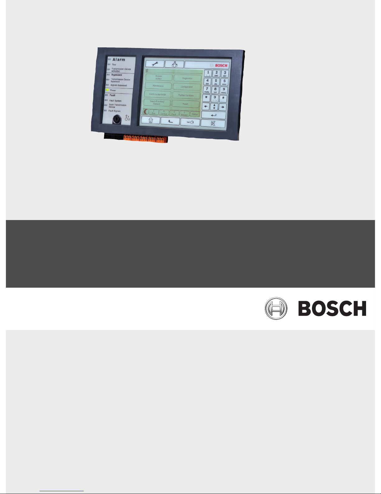
Panel Controller
MPC-xxxx-B | FPA-1200-MPC
en Operation guide


Panel Controller Table of Contents | en 3
Bosch Sicherheitssysteme GmbH Operation guide F.01U.076.969 | 6.0 | 2010.04
Table of Contents
1 For your information 8
1.1 Depiction of steps 8
1.2 Calling up the start menu 8
1.3 Changing language display 9
1.4 Warranty and liability 9
1.5 Copyright 9
2For your safety 10
2.1 Symbols and notes used 10
2.2 Operating the touch screen 10
2.3 Maintenance 11
2.4 Usage in accordance with regulations 11
2.5 Skills required by personnel 11
3 All functions at a glance 12
3.1 Calling up the start menu 12
3.2 Bypass/Isolate 12
3.2.1 Bypass 12
3.2.2 Isolate 12
3.3 Diagnostics 13
3.4 Maintenance 14
3.4.1 Walktest 14
3.4.2 Change language 15
3.4.3 Activate Outputs 15
3.4.4 Activate the transmission device 15
3.4.5 Detector removal 15
3.4.6 History Log 15
3.4.7 Change device on V.24 Interface 15
3.5 Configuration 16
3.6 Switching to day or night mode 16
3.7 Further functions 17
3.8 Search Function/Element 18
3.9 Reset 18
4 In overview 19
4.1 Operating elements 19
4.2 Display elements 21
4.3 Touch screen 21
4.4 Standby display 23
4.5 Display service department 24
5 Operating principle 25
5.1 Logging on and off 25
5.1.1 Logging in 25
5.1.2 Logging out 26

4 en | Table of Contents Panel Controller
F.01U.076.969 | 6.0 | 2010.04 Operation guide Bosch Sicherheitssysteme GmbH
5.2 Access authorization 26
5.3 Calling up the start menu 26
5.4 Selecting the menu 26
5.5 Returning to the previous selection 27
5.6 Working with lists 27
5.6.1 Scrolling through lists 28
5.6.2 Various states of list fields 29
5.6.3 Selecting element/function 29
5.6.4 Assigning mode 30
5.7 Search Function/Element 30
5.7.1 Search by name 30
5.7.2 Searching by number 31
5.8 Entering numbers and text 31
5.8.1 Changing an entry 32
5.8.2 Deleting all numbers 32
5.9 Changing language display 32
5.9.1 Entering key combination 32
5.10 Switching between status bars 33
5.11 Logical and physical addressing 33
6 Networked panels 34
6.1 Icons on the display 34
6.2 Network addressing 35
6.3 Establishing a remote connection with a networked panel 35
6.4 Terminating a remote connection with a networked panel 36
6.5 Isolating and restricted connection 36
7 Remote keypad 37
7.1 Operation and display 37
8Alarm 38
8.1 Types of alarm 38
8.2 Entry delays 39
8.3 Day and night mode 40
8.4 Alarm message to the panel 41
8.4.1 Optical and acoustic signals 41
8.4.2 Displaying the detector zones in alarm state 41
8.4.3 Sequence of the alarm messages 42
8.4.4 Information about logical zones in the alarm state 42
8.4.5 The newest message 42
8.4.6 Displaying the individual detectors in a logical zone 43
8.4.7 Information about individual detectors 43
8.4.8 Displaying additional information 43
9 Fire alarm 44
9.1 Optical and acoustic signals 44
9.2 Acknowledging a message 44
9.3 Switching off internal buzzer 45

Panel Controller Table of Contents | en 5
Bosch Sicherheitssysteme GmbH Operation guide F.01U.076.969 | 6.0 | 2010.04
9.4 Switching external signaling devices on and off 45
9.5 Resetting external signaling devices and transmission devices 45
9.6 Triggering fire verification 46
9.6.1 Alarm verification 46
9.6.2 Starting time to investigate 46
9.6.3 Triggering alarm manually 47
9.7 Resetting alarm message 47
9.8 Bypassing detectors 48
10 Fault message 49
10.1 Calling up fault indication 49
10.2 Trouble message on the panel 50
10.2.1 Acknowledging a message 50
10.2.2 Sequence of the trouble messages 50
10.2.3 Information about malfunctioning element groups 50
10.2.4 The newest message 51
10.2.5 Displaying individual elements of an element group 51
10.2.6 Information about individual elements 52
10.2.7 Displaying additional information 52
10.2.8 Signals 53
10.3 Resetting malfunction message 53
10.4 Isolating an element 53
11 Bypass 54
11.1 Menu overview 54
11.2 Bypassing and un-bypassing elements 54
11.3 Displaying and un-bypassing bypassed element groups 55
11.4 Displaying list of all bypassed elements 55
11.4.1 Using the menu 55
11.4.2 Via the status bar 56
11.5 Bypassing/Un-bypassing buzzer 56
12 Isolate 57
12.1 Menu overview 57
12.2 Isolating and de-isolating elements 57
12.3 Displaying list of all isolated elements 58
12.3.1 Using the menu 58
12.3.2 Via the status bar 58
13 Diagnostics 59
13.1 Menu overview 59
13.2 Element details 59
13.3 Modules 60
13.4 Hardware 61
13.4.1 Address cards 61
13.4.2 Display 61
13.4.3 Serial Interface 62
13.4.4 CAN-Bus 62

6 en | Table of Contents Panel Controller
F.01U.076.969 | 6.0 | 2010.04 Operation guide Bosch Sicherheitssysteme GmbH
13.5 Panel Passport 62
13.6 LED Test on modules 63
13.7 Network 63
13.8 Electro-acoustic systems 64
14 Maintenance 65
14.1 Menu overview 65
14.2 Changing language display 65
14.3 Activate Outputs 66
14.4 Activate Transmission Device 66
14.5 Detector removal 67
14.6 Change device on V.24 Interface 67
14.7 Bypassing/Un-bypassing buzzer 67
15 Maintenance – walktest 68
15.1 Walktest groups 68
15.1.1 Adding or deleting elements 69
15.2 Starting and ending walktest 70
15.2.1 Starting the walktest 70
15.2.2 Ending the walktest 71
15.3 Ending walktest for all elements 71
15.4 Displaying tested or untested elements 71
15.5 Assigning tested elements to a walktest group 72
16 Maintenance – history log 73
16.1 Selecting filters 73
16.2 Setting filters 73
16.3 Change Filter 74
16.4 Combining several filters 74
16.5 Status bar functions 74
16.6 Printing out data 75
17 Day and night mode 76
17.1 Switching between day and night mode 76
17.2 Showing details 77
17.3 Changing the time for resetting to night mode 78
18 Configuration 79
18.1 Menu overview 79
18.2 Input / Output Group Set Up 79
18.2.1 Adding or deleting elements 79
18.2.2 Change name 81
18.3 Group setting 81
18.3.1 Adding or removing 81
18.4 Detector sensitivity 82
18.5 Operator 83
18.5.1 Change password 83
18.5.2 Change universal password 83

Panel Controller Table of Contents | en 7
Bosch Sicherheitssysteme GmbH Operation guide F.01U.076.969 | 6.0 | 2010.04
18.5.3 Set Default Password 84
18.6 Rename elements 84
18.7 Overview 84
19 Further functions 85
19.1 Menu overview 85
19.2 Change Date / Time 85
19.3 Master password 85
19.3.1 Enter the master password that is valid indefinitely 86
19.3.2 Enter the 24-hour master password 86
19.4 Remote Access 86
19.5 Change password 87
19.6 Performing a fire drill 87
19.7 Alarm Counters 88
20 Reset 89
20.1 Menu overview 89
20.2 Resetting elements 89
21 Search Function/Element 90
21.1 Menu overview 90
21.2 Searching for function and device description 90
21.3 Search element 90
Index 91
8 en | For your information Panel Controller
F.01U.076.969 | 6.0 | 2010.04 Operation guide Bosch Sicherheitssysteme GmbH
1 For your information
This operation guide contains important information and notes on operating the FPA-5000
and FPA-1200 fire panels.
Using the step-by-step directions, you can familiarize yourself with the individual functions:
– Section 4 In overview, page 19 provides an overview of the operating and display elements
and the touch screen.
–In Section 5 Operating principle, page 25, you will learn how to navigate through the
individual menus and which selection possibilities are available to you.
Each function is described in detail in an individual chapter.
You will find specific topics in the table of contents. If you are already practiced in the
handling of menus, you can use the overview of all menus in Section 3 All functions at a glance,
page 12.
1.1 Depiction of steps
The sequence of steps that you need to execute a function is depicted as follows:
1. In the start menu, select Bypass Block.
2. Bypass
In more detailed form:
1. Call up the start menu.
2. Select Bypass/Isolate.
3. Select Bypass.
1.2 Calling up the start menu
1. Press the "home" key.
You can use this key to return from any submenu back to the start menu.
NOTICE!
In standby mode, the standby screen is displayed. This contains different information
depending on the configuration.
To call up the start menu or change the language display, see Section 5 Operating principle,
page 25.
NOTICE!
The display changes from each menu element to the standby display if no entries are made
within one minute.
Panel Controller For your information | en 9
Bosch Sicherheitssysteme GmbH Operation guide F.01U.076.969 | 6.0 | 2010.04
1.3 Changing language display
The panel language can be changed quickly with a shortcut; see the following instruction To
change the panel language using the menu, see Section 5.9 Changing language display,
page 32.
1. Select the "home" key.
2. Then press 1 on the alphanumeric keypad immediately after this.
3. Select OK to confirm the entry or Cancel to cancel the operation.
A list of the existing languages is displayed.
4. Select the language you require.
The displays are displayed in the selected language.
1.4 Warranty and liability
Warranty and liability claims for personal and property damage are excluded if these were
caused by one or several of the following causes:
– Use of the FPA-5000 and FPA-1200 fire panels contrary to the regulations
– Improper set-up, installation, start-up, operation or maintenance
– Disregarding of the user manual
– Subsequent constructional changes
– Faulty repairs
– Catastrophes, influence of foreign bodies, and force majeure.
Without the permission of Bosch, no changes or additions to or rebuilding of the panel
including the panel controller may be undertaken.
Rebuilding requires written permission. In case of non-approved constructional changes, any
warranty claims against Bosch are voided.
1.5 Copyright
Bosch retains the complete copyright to the whole documentation. Without the express
written permission of Bosch, no part of these documents may be duplicated or transmitted in
any form.
Bosch reserves the right to make changes to this manual without prior notice.
NOTICE!
After a system reboot following a power cut or battery failure, the default language set in the
FSP-5000-RPS is displayed again.

10 en | For your safety Panel Controller
F.01U.076.969 | 6.0 | 2010.04 Operation guide Bosch Sicherheitssysteme GmbH
2 For your safety
Before using the device, familiarize yourself with these instructions. If you do not read and
understand these explanations, you will not be able to operate the device faultlessly.
The operating instructions do not do away with the need for training by authorized personnel.
This operation guide does not contain any general or special knowledge about safety issues.
Information on such issues is only given to the extent that it is needed for operation of the
device.
Ensure that you are familiar with all safety-related processes and regulations in your area. This
also includes how to behave in the event of an alarm and the initial steps to take if a fire
breaks out.
The operation guide should always be available on site. It is a statutory part of the system and
must be given to the new owner if the system is ever sold.
2.1 Symbols and notes used
The various chapters only contain whatever safety information and notes are required for
operation of the system. Warning notes and operator guidance notes are displayed in the
appropriate parts of the panel controller display for your benefit.
The following search symbols are used:
2.2 Operating the touch screen
Do not use any pointed or sharp objects when operating the touch-sensitive display. This
could damage the surface. Touch the touch screen with your finger (nail) or the stick attached
to the left-hand side of the panel controller.
NOTICE!
The panel controller may only be operated by trained personnel. See skills required by
personnel.
NOTICE!
The personal access code (consisting of user ID and password) must not be made known to
third parties.
CAUTION!
Text fields marked with this symbol contain warnings by which you must abide without fail —
for your own safety as well as that of the people around you
NOTICE!
Text fields marked with this symbol contain useful information to help you operate the FPA5000 and FPA-1200 fire panels.

Panel Controller For your safety | en 11
Bosch Sicherheitssysteme GmbH Operation guide F.01U.076.969 | 6.0 | 2010.04
2.3 Maintenance
Clean the touch screen and membrane keypad with a soft cloth only. If necessary, dampen the
cloth lightly with standard monitor cleaning agents. Do not use any aggressive cleaning agents
and ensure that no liquid enters the inside of the device.
2.4 Usage in accordance with regulations
The panel controller is designed for operating the FPA-5000 and FPA-1200 fire panels. It can
perform the following tasks:
– Displaying and processing various message types such as alarm and trouble messages
– Bypassing, isolating and resetting elements
– Performing a walktest
– Display diagnostic information about every LSN element
– Programming detectors (short texts and detector sensitivity)
– Performing a drill
– Saving, displaying and printing out events
– Switching the system to day or night mode.
2.5 Skills required by personnel
Display of event messages on the panel controller must only be processed by trained
personnel.
The system walktest and detector configuration must only be performed by trained,
authorized personnel.
12 en | All functions at a glance Panel Controller
F.01U.076.969 | 6.0 | 2010.04 Operation guide Bosch Sicherheitssysteme GmbH
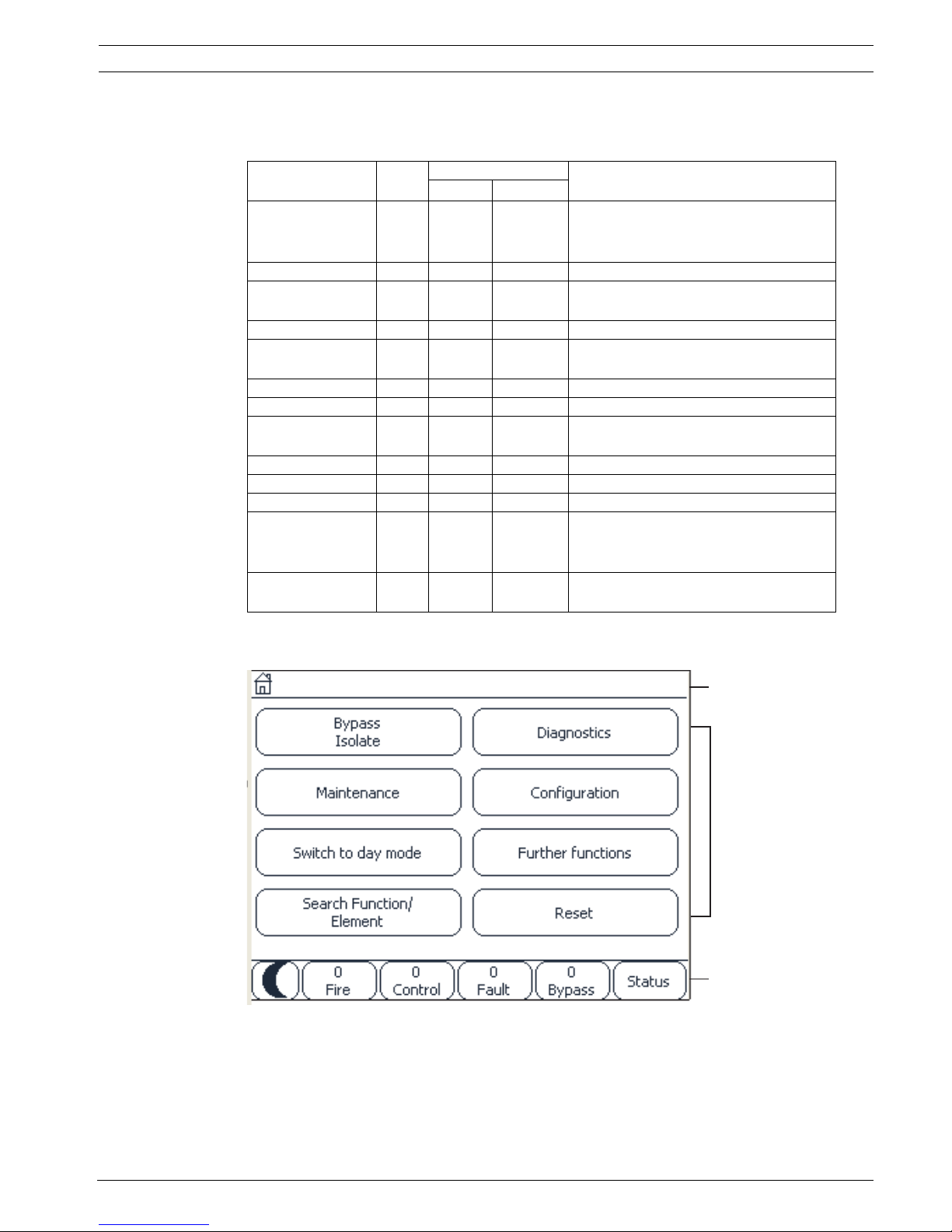
3 All functions at a glance
3.1 Calling up the start menu
Press the "home" key to return to the start menu from any submenu.
3.2 Bypass/Isolate
3.2.1 Bypass
Show bypassed devices
– Display of a list of all bypassed elements:
– Un-bypassing the bypassed elements.
Select by number
– Display of a list of all bypassed elements:
– Search for an element in a list by entering the number.
– Un-bypassing or bypassing an element.
3.2.2 Isolate
Show blocked devices
– Display a list of all isolated elements
– De-isolate isolated elements
NOTICE!
The display changes from each menu element to the standby display if no entries are made
within one minute; see also Section 4.4 Standby display, page 23.
Bypass
Block
-> Bypass -> Show bypassed devices Select by
number
Bypass buzzer Printer
Block NAC Transmission
device
HVAC Doorholder
Detector Logical zone Extinguishing
system
Annunciator
Bypass group More... -> Control element Interface
module
Bypass
Block
-> Bypass Show blocked devices Select by
number
Block Group Printer
Block -> Sounder Strobe HVAC Doorholder
Transmission device Detector Extinguishing
system
Annunciator
Logical zone More... -> Control element Interface
module
Panel Controller All functions at a glance | en 13
Bosch Sicherheitssysteme GmbH Operation guide F.01U.076.969 | 6.0 | 2010.04
Select by number
– Display a list of all elements that can be isolated
– Search for an element in a list by entering the number
– Isolate or de-isolate an element
3.3 Diagnostics
Element details
– All info for one element: Display all diagnostic information about an element on a loop of
an LSN module.
– Info for element group: Select and display specific diagnostic information about several
elements in the selected LSN module.
– Info for all elements on the module: Select and display specific diagnostic information
about all LSN elements of the selected LSN module.
Modules
– Module passport: Display diagnostic information for each individual module: production
data, software version, CAD-ID, compatibility.
– Module Compatibility: Display the software version of the selected module in
comparison with the version of the panel software.
– Module status: Display hardware diagnostic data of the selected module.
Only for LSN modules:
– Module status and counters
– Reset counters: Reset the counters that record the frequency with which various events
occur.
Hardware
– Address cards: Additional display per card slot of the serial number and number of
addresses per card.
– Display
– LED test: Test all LED displays on the panel controller. These remain lit for the
duration of approx. five seconds.
– Key test: Test the operativeness of the membrane keypad.
– Display test: Test the operativeness of the display.
– Display touch test: Test the operativeness of the touch-sensitive surface.
– Adjust touch screen (calibration): Adjust the location precision when touching the
touch screen.
– Serial interface: Display statistical data for the transmission.
– CAN bus: Display status of CAN interfaces.
Panel passport
Display diagnostic information such as manufacturing data or software version of the panel
controller.
Diagnostics -> Element details Modules
Hardware Panel passport
LED test on modules History log
Network VAS
14 en | All functions at a glance Panel Controller
F.01U.076.969 | 6.0 | 2010.04 Operation guide Bosch Sicherheitssysteme GmbH
LED test on modules
Test LED displays of individual modules and simultaneously test all LED displays.
History log
See Maintenance – history log
Network
Information on availability of other nodes within the system network.
VAS
Information on all connected electro-acoustic systems that are used for voice evacuation
systems.
3.4 Maintenance
3.4.1 Walktest
Start / End walktest
Elements for the walktest are selected in this submenu. The following possibilities are offered
for selection:
– Select by number:
Display of a list of all elements:
Search for an element in a list by entering the number.
– Walktest group
– Loop
– Logical zone
– Elements
– Transmission device
– Control element
– More...
– DACT
– Key deposit
– Battery
– Mains power
When the walktest is complete, the following selection options are available:
– Add the tested elements to a different walktest group (Assign tested elements to
walktest group).
– Continue the walktest (No).
– Display tested or untested elements (Not tested, Tested).
Create / Change walktest group
– Deleting or adding individual elements to specified walktest groups.
– Delete all elements in a walktest group.
Maintenance -> Walktest Change language
Activate outputs Activate
transmission device
Remove detector History log
Change device
at V.24 interface
Bypass buzzer

Panel Controller All functions at a glance | en 15
Bosch Sicherheitssysteme GmbH Operation guide F.01U.076.969 | 6.0 | 2010.04
3.4.2 Change language
Change the language of the display (Change language).
3.4.3 Activate Outputs
Activate outputs:
– Select by number:
Display of a list of all controllable elements.
Search for an element in a list by entering the number.
– Sounder
– Strobe
– HVAC
– More...
Start and terminate activation of the selected elements.
3.4.4 Activate the transmission device
Activate a selected transmission unit (Activate transmission device).
3.4.5 Detector removal
Bypass all sounders and transmission devices for 15 minutes while a detector is being
removed (Remove detector).
3.4.6 History Log
– Filtering and displaying specific data
– Combining various filters
– Print out all filtered data or a specific part of the data
The following filters are available:
3.4.7 Change device on V.24 Interface
Assign a different device to the V.24 interface (Change device at V.24 interface).
Filter Data, filtered by...
Without filter All data
Show all
Delete filter
Display all data with specification of event number, date, time,
element number and message type. Existing filters are
deleted.
Period Starting date, end date and time
Event types Message types, such as Fault
Device types Device types, such as Detectors
Address range Address range within a system
User commands Selected function fields such as Acknowledge or Reset
Walktest Elements switched to walktest mode

16 en | All functions at a glance Panel Controller
F.01U.076.969 | 6.0 | 2010.04 Operation guide Bosch Sicherheitssysteme GmbH
3.5 Configuration
Set input / output groups
– Input group or Output group
– Displaying the assigned elements.
– Add or delete elements.
– Rename group names.
Set groups
– Bypass group, isolate group or walktest group
– Displaying the assigned elements.
– Add or delete elements.
– Rename walktest, bypass and isolate groups.
Detector sensitivity
Change the sensitivity of individual detectors or zones. Two selection options are available: a
default sensitivity and an alternative sensitivity assigned in the FSP-5000-RPS programming
software.
Operator
If the same password is used per access level, the following options are offered:
– Change universal password
The same password can be configured for each access level in the FSP-5000-RPS
programming software. The password for access levels two to four can be changed.
If every user has a different password, the following options are offered:
– Change operator data
Change a user's password.
– Set default password
Reset an operator's password to his/her previous password.
Rename elements
Change the description of the elements.
Overview
Information on valid configuration of the system.
3.6 Switching to day or night mode
– Switch to day or night mode
– In day mode: Set the reset time to night mode for the current day.
Configuration -> Set input / output groups Set groups
Detector sensitivity Operator
Rename elements Overview

Panel Controller All functions at a glance | en 17
Bosch Sicherheitssysteme GmbH Operation guide F.01U.076.969 | 6.0 | 2010.04
3.7 Further functions
Change date / time
Changing time and date
Master password
One of the two options will be offered, depending on how the panel is programmed:
– Entering a master password that is valid indefinitely.
This password cannot be changed and is available from the relevant Bosch branch on
request
– Entering a master password that is valid for a specified period of time. This password is
only valid for 24 hours and must first be requested; see Section 19.3 Master password,
page 85.
After the password has been entered, various options are offered depending on the
configuration; see Section 18.5 Operator, page 83.
Drill
Start and terminate a fire drill During the drill, fire alarms, trouble messages and home
automation alarms are displayed.
Remote access
Creating a connection to the teleservice.
Change password
Depending on how the panel is programmed, the option of changing the password for every
user is offered.
Alarm counters
– Display the number of internal and external alarm messages and the number of service
alarms that were reported during the lifetime of the panel.
– Reset the alarm counter for each alarm type
Further functions -> Change date / time Master password
Remote access Change password
Drill Alarm counters
18 en | All functions at a glance Panel Controller
F.01U.076.969 | 6.0 | 2010.04 Operation guide Bosch Sicherheitssysteme GmbH
3.8 Search Function/Element
Search function
– Display a list of all functions and device descriptions in alphabetical order.
– Select a function or device description from the list.
Go to element
Display of a list of all elements that are connected to the system and select an element from
this list in order to display more detailed information.
– by logical address: Search for an element in the list by entering the logical addressing.
– by physical address: Search for an element in a list by entering the physical addressing.
– By description: Search for an element in a list by entering the description.
3.9 Reset
Search
function / element
-> Search function
Go to element
Reset -> Event type Scope
Logical zone Detector
This panel

Panel Controller In overview | en 19
Bosch Sicherheitssysteme GmbH Operation guide F.01U.076.969 | 6.0 | 2010.04
4 In overview
This chapter contains information about the following elements of the panel controller:
– Section 4.1 Operating elements
– Section 4.2 Display elements
– Section 4.3 Touch screen
– Section 4.4 Standby display
– Section 4.5 Display service department
4.1 Operating elements
The operating elements include points 1 - 3.
Function keys
To select a function, press the appropriate membrane key.
The following functions can be executed with the function keys:
1 Function keys 3 Key switch
2 Alphanumeric keypad 4 LED display
0
Bypass
Isolate
Maintenance
Switch to d ay mode
Search F unction/
Element
Diagnostics
Configuration
Further functions
Reset
000
Fire
Control
Fault Bypass
Status
Tes t
Transmission Dev ice
activated
Bypassed
bypassed
Transmission Dev ice
Signals bypassed
Power
Fault
Fault Sy stem
Fault Transmission Devic e
Fault Si gnal s
Alarm
1
1
2
1
3
4
Display a list of the networked panels and establish a remote
connection with a networked panel (only valid for FPA-5000) or a
remote keypad.
Display the address of the service department, if programmed.
"Home" key. Call up the start menu.
20 en | In overview Panel Controller
F.01U.076.969 | 6.0 | 2010.04 Operation guide Bosch Sicherheitssysteme GmbH
Alphanumeric keypad
Entry of letters, special characters, and numbers.
Key switch
The key switch has two programmable key positions. Depending on the configuration, it is
possible to switch between day and night operation, for example.
Return to the previous selection.
"Key" key. Log in and out: Enter user ID and password.
Temporarily switch off the internal buzzer.
"Left arrow" key. Move the cursor one place to the left on the search
screen.
"Right arrow" key. Move the cursor one place to the right on the search
screen.
"Double arrow" key. Switch between status bars if two or more are
present.
Call up the status bar to scroll rapidly through the lists.
"Enter" key. Confirm an alphanumeric entry.
Confirm an entry that is not confirmed by selecting the OK field on the
touch screen.
NOTICE!
Only give the key to people who have been trained to operate the panel controller and who
have knowledge in the area of fire protection. Otherwise, operation may be incorrect and
people may be injured.
To prevent possible misuse, remove the key after operation and store it in a secure location.
Panel Controller In overview | en 21
Bosch Sicherheitssysteme GmbH Operation guide F.01U.076.969 | 6.0 | 2010.04
4.2 Display elements
LED display
4.3 Touch screen
Display Color Light signal Meaning
Steady Flashes
Alarm Red x Panel is in alarm state
Also continuously on in event of Fire
PAS
Walktest Yellow x System is being tested
Transmission
Device activated
Red x Transmission device is activated
Bypassed Yellow x Elements are bypassed and/or isolated
Trans. Dev.
disabled
Yellow x Transmission device is not activated
Signals disabled Yellow x Signaling devices are not activated
Operation Green x Panel is operational
Green x Panel controller is booting and is not
yet operational
Green x Power supply fault
Fault Yellow x Fault message present
Fault System Yellow x Main processor is malfunctioning
Fault
Transmission
Device
Yellow x Transmission device is malfunctioning
Fault Signals Yellow x External signaling device
malfunctioning
1Info bar
2Menu field
3 Status bar
1
2
3
22 en | In overview Panel Controller
F.01U.076.969 | 6.0 | 2010.04 Operation guide Bosch Sicherheitssysteme GmbH
Info bar
Menu field
To select a main menu, touch the corresponding menu field on the touch screen. I
Section 3 All functions at a glance, page 12, there is an overview of all main menus with their
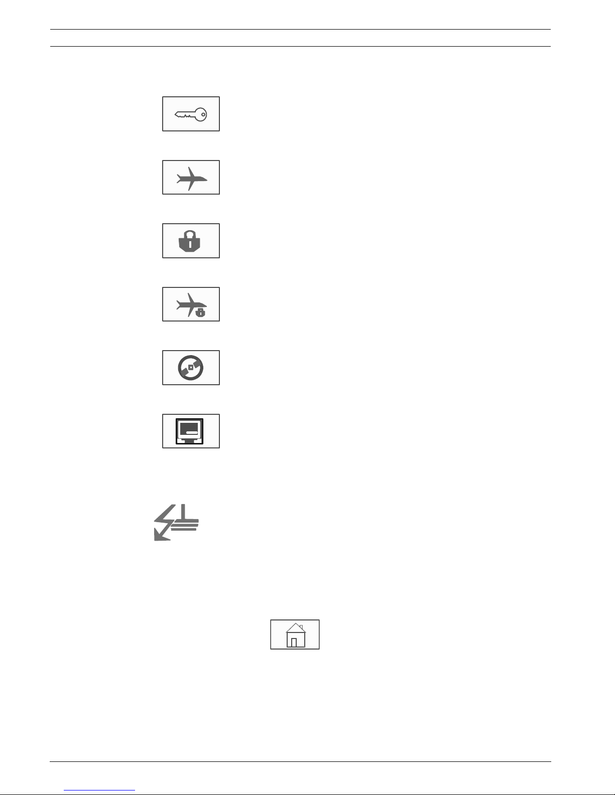
respective submenus.
As long as an operator is logged in, this symbol will be displayed
on the right-hand side of the info bar.
There is a remote connection with a networked panel or a remote
keypad.
The networked panel is operated from another panel or from a
remote keypad and is blocked for operation.
There is a remote connection between panel A and a networked
panel B or a remote keypad, and panel A is operated
simultaneously from another panel C.
There is a restricted connection to the networked panel or a
remote keypad.
This icon is only displayed on the remote keypad if no connection
has yet been established.
Panel 4 - 1 I Level 4
logged in
The network address and the access authorization of the
operator who has logged in (4) are displayed.
This symbol is displayed if a ground fault occurs in the system.
The names of the selected menus are also listed. Having the
menu path displayed will assist your orientation.
For reasons of space it is not always possible to display the
complete path. The selected menu and the menu you are
currently in are always displayed first.
Example:
The following path is displayed in the Sounder submenu of the
Block main menu:
* Bypass Block\Block\Sounder
Panel Controller In overview | en 23
Bosch Sicherheitssysteme GmbH Operation guide F.01U.076.969 | 6.0 | 2010.04
Status bar
This status bar is available on each menu. In addition, other status bars are offered in some
menus; see also Section 5.10 Switching between status bars, page 33:
The leading number specifies the number of elements in the respective state:
In addition it is possible to display an overview of the type and nature of all message types
received by the panel:
To display the individual elements, touch the relevant field with your finger.
The Control and Trouble status fields are identified by the letters "B" and/or "C":
– "B" means that controllers for type B fire safety equipment (G-B) are affected (e.g.
control elements without acknowledgement).
– "C" means that controllers for type C fire safety equipment (G-C) are affected (e.g.
extinguishing systems).
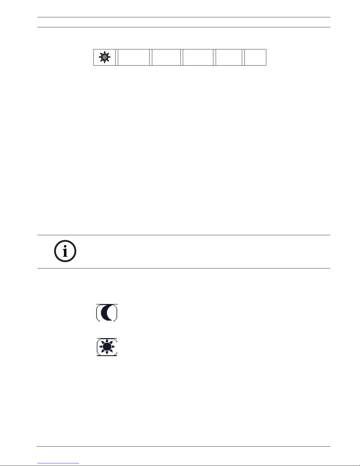
4.4 Standby display
If the panel is in standby mode, the standby display is shown.
On the standby display, the following information is displayed:
– Date
–Time
or
Depending on the configuration, additional information may be displayed.
In a networked fire detection system, further icons can be displayed in the standby display
depending on the network setting; see Section 6 Networked panels, page 34.
0
Fire
0
Control8Trouble
0
Bypass Status
Fire Elements that have triggered a fire alarm
Control Elements that are activated
Trouble Elements that have reported a fault
Bypass Bypassed or isolated elements
Status Display of a list of the various message and status types and the
number of elements in the respective state
NOTICE!
The display changes from each menu element to the standby display if no entries are made
within ten minutes.
If a gray display is shown, gently touch the touch screen to show the standby display
Night mode
Day mode
24 en | In overview Panel Controller
F.01U.076.969 | 6.0 | 2010.04 Operation guide Bosch Sicherheitssysteme GmbH
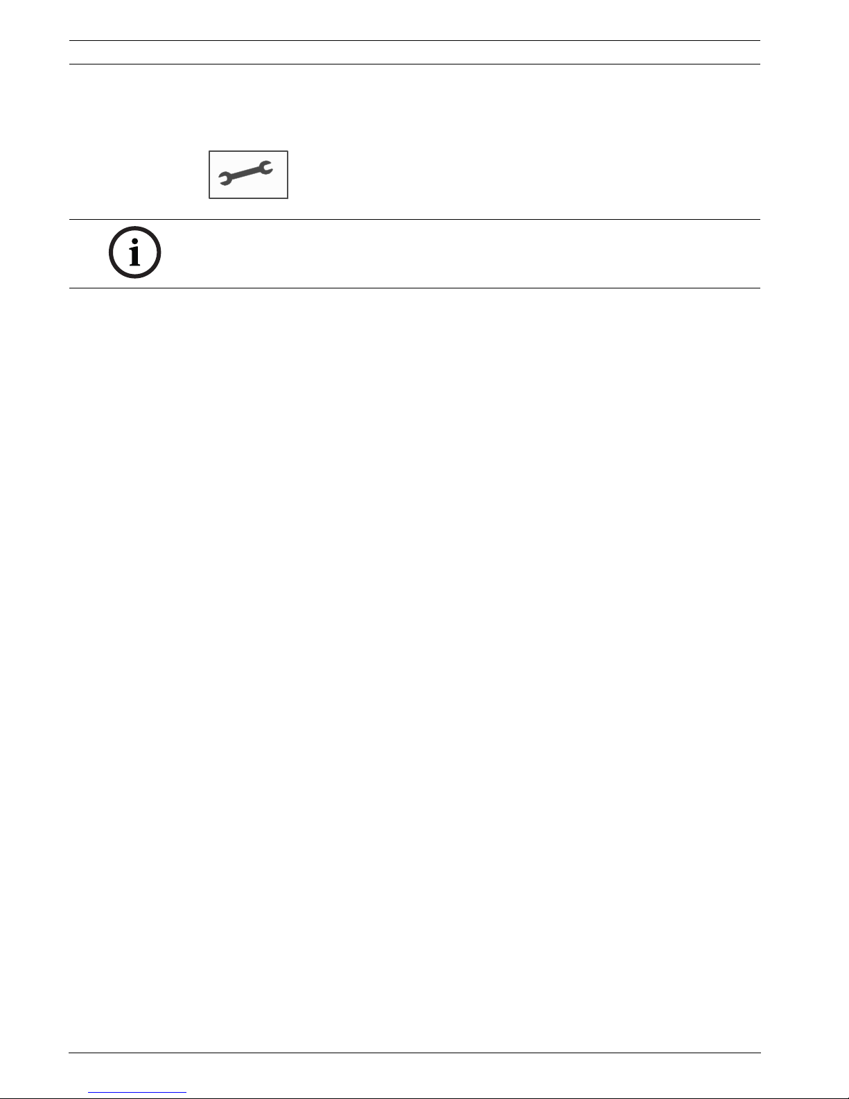
4.5 Display service department
To display the address of the support service, please press:
NOTICE!
Information about the support service is only displayed if the information has already been
entered in FSP-5000-RPS.
Panel Controller Operating principle | en 25
Bosch Sicherheitssysteme GmbH Operation guide F.01U.076.969 | 6.0 | 2010.04
5 Operating principle
In addition to a brief menu overview, this chapter contains information about the following
points:
– Section 5.1 Logging on and off, page 25
– Section 5.2 Access authorization, page 26
– Section 5.3 Calling up the start menu, page 26
– Section 5.4 Selecting the menu, page 26
– Section 5.5 Returning to the previous selection, page 27
– Section 5.6 Working with lists, page 27
– Section 5.7 Search Function/Element, page 30
– Section 5.8 Entering numbers and text, page 31
– Section 5.9 Changing language display, page 32
– Section 5.10 Switching between status bars, page 33
– Section 5.11 Logical and physical addressing, page 33
5.1 Logging on and off
To gain access to access levels 2 to 4, it is necessary to log in. The prerequisite is that you
have access authorization.
5.1.1 Logging in
To log in to the panel controller:
1.
Press the "key" key.
The login window is displayed:
2. Enter your user ID in the first field.
Refer to Section 5.8 Entering numbers and text, page 31 for information on how to enter
numbers.
3. Enter your password in the second field.
On the display, each digit of the password is indicated with an asterisk so that nobody
else can see the password.
NOTICE!
To log in, you need a user ID and password.
Depending on your access authorization, you can use only particular functions.
In the following cases, you will be asked to enter a password:
– You are not logged on and want to select a function for which a password is required.
– You are already logged in but a higher access authorization is required for the function
you have selected.
NOTICE!
If you do not have your own password, enter the following numbers: 000000.
26 en | Operating principle Panel Controller
F.01U.076.969 | 6.0 | 2010.04 Operation guide Bosch Sicherheitssysteme GmbH
4. Select OK to confirm the entries or Cancel to cancel the operation.
Refer to Section 19.5 Change password, page 87 for information on how to set up your
own password.
The standby display is shown.
As long as an operator is logged in, the key icon will be displayed on the info bar.
In addition, the user ID of the user who has logged on is displayed on the start page on the
info bar.
5.1.2 Logging out
1. To log out of the panel controller, press the "key" key:
An input window with the request Log off? is displayed:
2. Select Yes to confirm the request or No to cancel the operation.
5.2 Access authorization
If you select a function for which a particular access authorization is required and no user with
the appropriate authorization is logged on, you will be asked to enter your user ID and
password.
Access authorizations are assigned for access levels two to four. Only a few functions can be
used on access level one, while all functions can be used on access level four.
To check the access authorization of the person who is logged in, press the "key" key after
logging in:
The relevant access authorization is displayed.
5.3 Calling up the start menu
Press the "home" key to return to the start menu from any submenu.
5.4 Selecting the menu
In order to select a menu in the start menu, touch the field you require with your finger:
The submenus are displayed.
To select a submenu, gently touch the required field.
NOTICE!
In the FSP-5000-RPS programming software, a time span can be specified after which an
operator who is logged in to the panel controller is logged out.
NOTICE!
Depending on your access authorization, you can only use certain functions of the panel
controller.
NOTICE!
The display changes from each menu element to the standby display if no entries are made
within one minute; see also Section 4.4 Standby display, page 23.
Panel Controller Operating principle | en 27
Bosch Sicherheitssysteme GmbH Operation guide F.01U.076.969 | 6.0 | 2010.04
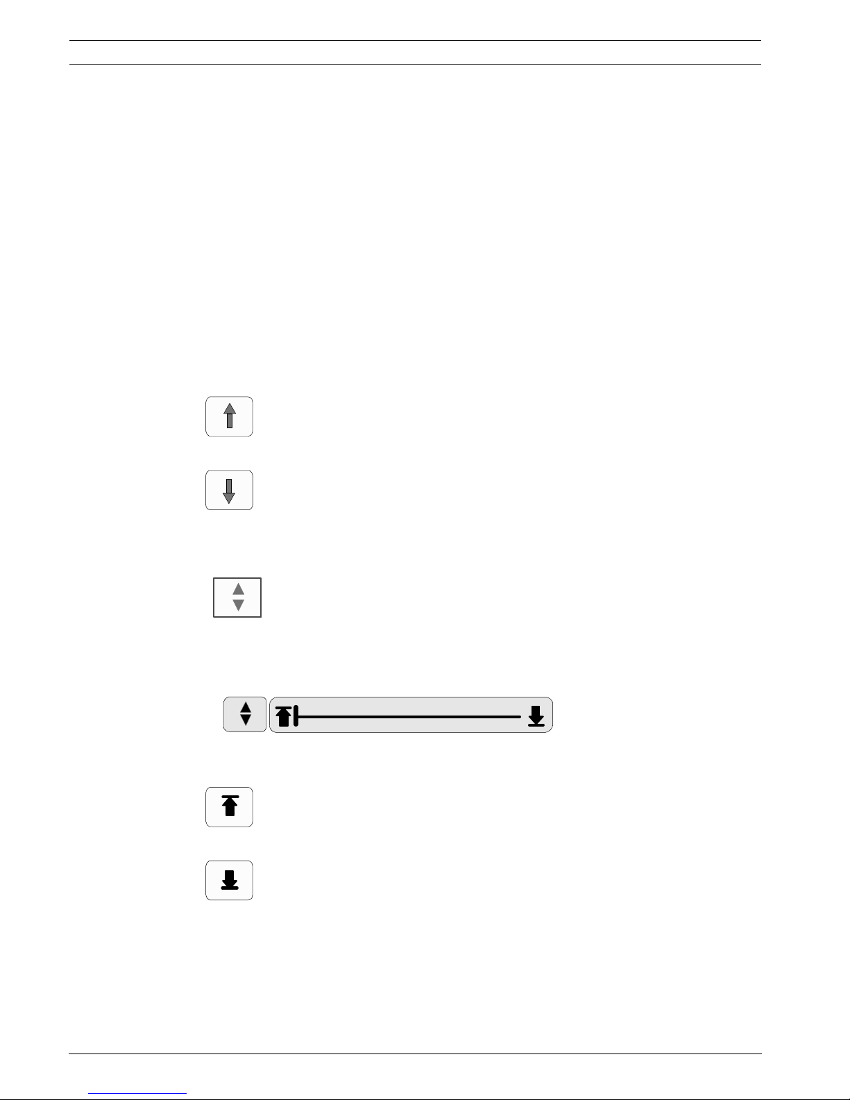
5.5 Returning to the previous selection
To return to the previous selection, press the "Back" key:
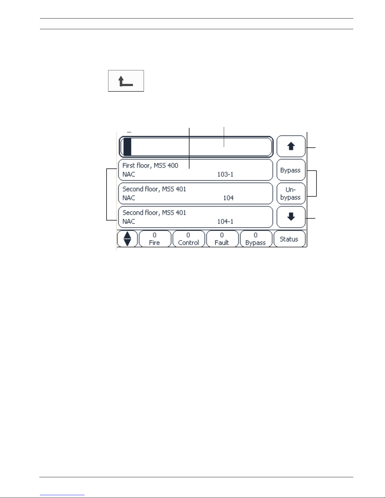
5.6 Working with lists
In many menus, elements are displayed in lists. The elements are sorted either by description
or address. Up to three different sorting criteria can be offered:
– By description: sorted by description in alphabetical order; addressing also given.
– By number: sorted in ascending orderby numbers (logical or physical addressing);
description also given.
– By number (no description shown): sorted in ascending order by numbers (logical or
physical addressing); the numbers are depicted in number blocks without specification
of the description.
This list is only offered when detectors and logical zones are being selected.
1List 4Arrows
2 List field 5 Function fields
3Search mask
1
2
3
4
4
5
28 en | Operating principle Panel Controller
F.01U.076.969 | 6.0 | 2010.04 Operation guide Bosch Sicherheitssysteme GmbH
Example:
To display a list of all existing detectors sorted by description in the Bypass submenu, select
the following in the start menu:
1. Bypass Block
2. Bypass
3. Detector
Three sorting criteria are offered for selection:
– By description
– By number
– By number (no description shown)
1. Select By description.
A list of all detectors is displayed, sorted in alphabetical order.
5.6.1 Scrolling through lists
On the display, only a limited number of list fields can be displayed.
Select the "up arrow" key to scroll back through a long list:
Select the "down arrow" key to scroll forward through the list:
An arrow is only displayed if scrolling is possible.
Rapid scrolling:
To scroll quickly through a list, press the "double arrow" key on the membrane keypad or on
the status bar of the display.
A scrollbar appears on the status bar:
Gently touch the horizontal line to jump to a particular place.
To jump to the beginning of a list, touch:
To jump to the end of a list, touch:
Panel Controller Operating principle | en 29
Bosch Sicherheitssysteme GmbH Operation guide F.01U.076.969 | 6.0 | 2010.04
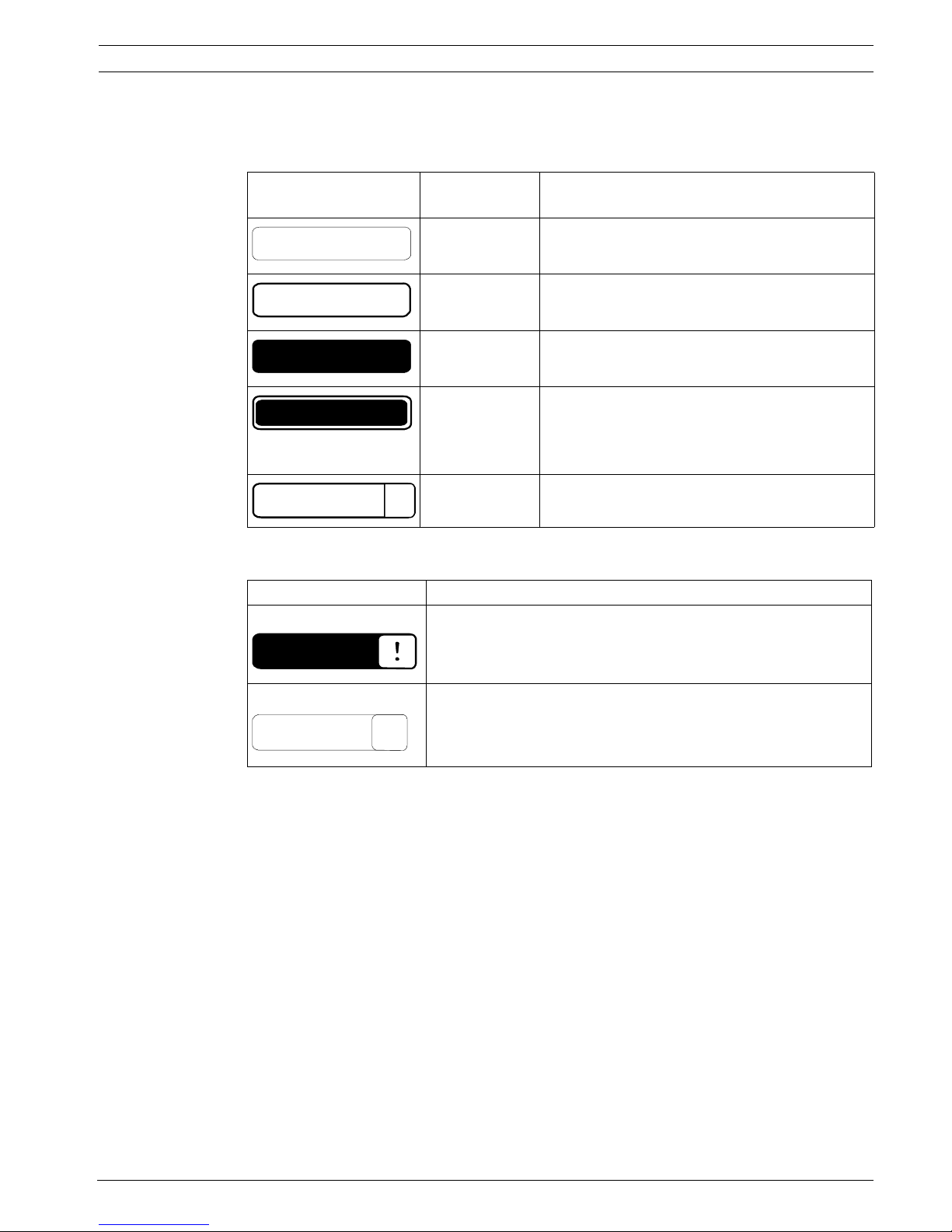
5.6.2 Various states of list fields
Various states can be assigned to an element or an element group, depicted by a list field. The
following table provides information about the possible states:
"Bypass" menu
In the Bypass menu, list fields can display additional information; see the following table:
5.6.3 Selecting element/function
To select elements/functions from a list, touch one or more list fields on the touch screen
with your finger.
In order to scroll forward or backward, select the up arrow (back) or the down arrow
(forward):
To scroll quickly using the scrollbar, select the "double arrow" key on the membrane keypad.
The activated list field is marked.
To search for and display a particular element; see Section 5.7 Search Function/Element,
page 30.
List field State of
list field
Meaning
normal Element in normal state
marked Selected element
Mode assigned The element was assigned the bypassed mode;
seeSection 5.6.4 Assigning mode, page 30.
Mode assigned
and marked
The selected element has already been assigned
a particular mode. It is selected in order to reset
it to the original mode;
a bypassed element is unbypassed, for example.
In reset mode The resetting of the element is not yet complete.
List field In the Bypass menu
The bypassed element is in alarm mode.
If it is un-bypassed, it triggers a fire alarm.
To display more information, press the right-hand field.
Display a bypass group that consists of several elements.
In order to display a list of all elements of the bypass group,
press the right-hand field.
TEXT
TEXT
TEXT
TEXT
R
TEXT
TEXT
Details
TEXT
 Loading...