

Page 1
FMR-7036
Installation Instructions
EN
Fire Annunciator Keypad
Page 2

FMR-7036 | Fire Annunciator Keypad | Contents
Contents
Contents ...........................................................................2
1.0 Notice .................................................................3
2.0 Device Description..........................................3
3.0 Installing the Reference Card.......................3
4.0 Mounting the FMR-7036.................................3
4.1 Surface Mounting...............................................3
4.2 Electrical Box Mounting....................................3
5.0 Setting the FMR-7036 Address......................4
6.0 Wiring the FMR-7036......................................4
7.0 FMR-7036 Programming ................................5
7.1 FPD-7024 Local Programming .........................5
7.2 FPD-7024 Remote Programming .....................5
8.0 FMR-7036 Operation.......................................5
8.1 Silence .................................................................5
8.2 Reset ....................................................................6
8.3 Scrolling Buttons ................................................6
8.4 Keylock Switch...................................................6
8.5 Display.................................................................6
8.6 Reset Switch........................................................6
9.0 Troubleshooting...............................................7
10.0 Specifications....................................................7
Figures
Figure 1: FMR-7036 Fire Annunciator Keypad.......3
Figure 2: Reference Card Installation .......................3
Figure 3: Mounting Hole Locations ..........................4
Figure 4: Inside View of FMR-7036 Keypad ...........4
Figure 5: FMR-7036 Address Jumper Settings.........4
Figure 6: FMR-7036 Wire Connections....................5
Tables
Table 1: FMR-7036 LED Functions.........................6
Table 2: FMR-7036 Troubleshooting Tips..............7
Table 3: FMR-7036 Specifications............................7
2 Bosch Security Systems, Inc. | 9/08 | F01U010584-01
Page 3
FMR-7036 | Fire Annunciator Keypad | 1.0 Notice
.
1.0 Notice
These instructions cover the installation of the Bosch
Security Systems, Inc. FMR-7036 Fire Annunciator
Keypad in a fire system supervised by a Bosch FPD7024 Fire Alarm Control/Communicator.
Install, test and maintain the FMR-7036 according to
these instructions, NFPA 72, local codes, and the
authority having jurisdiction. Failure to follow these
instructions may result in failure of the device to
operate properly. Bosch Security Systems, Inc. is not
responsible for improperly installed, tested or
maintained devices.
NFPA 72 requires a complete system-wide
functional test be performed following any
modifications, repair, upgrades, or
adjustments made to the system’s
components, hardware, wiring,
programming, and software/firmware.
These instructions contain procedures to
follow in order to avoid personal injury and
damage to equipment.
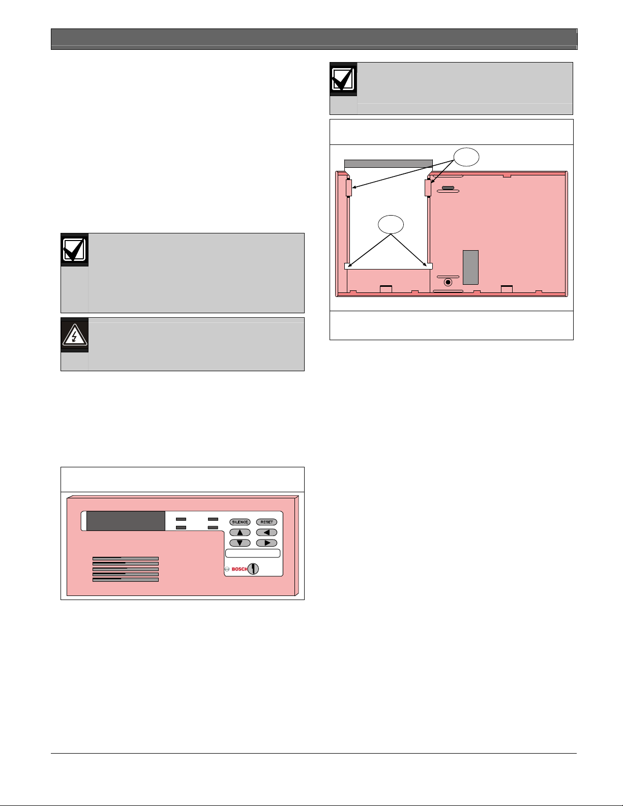
Install the reference card before securing
the keypad.
Figure 2: Reference Card Installation
FMR-7036 Reference Card
1
Slide reference guide between keypad holding tabs.
2
1 - Reference Card Stopper Tabs
2 - Holding Tabs
4.0 Mounting the FMR-7036
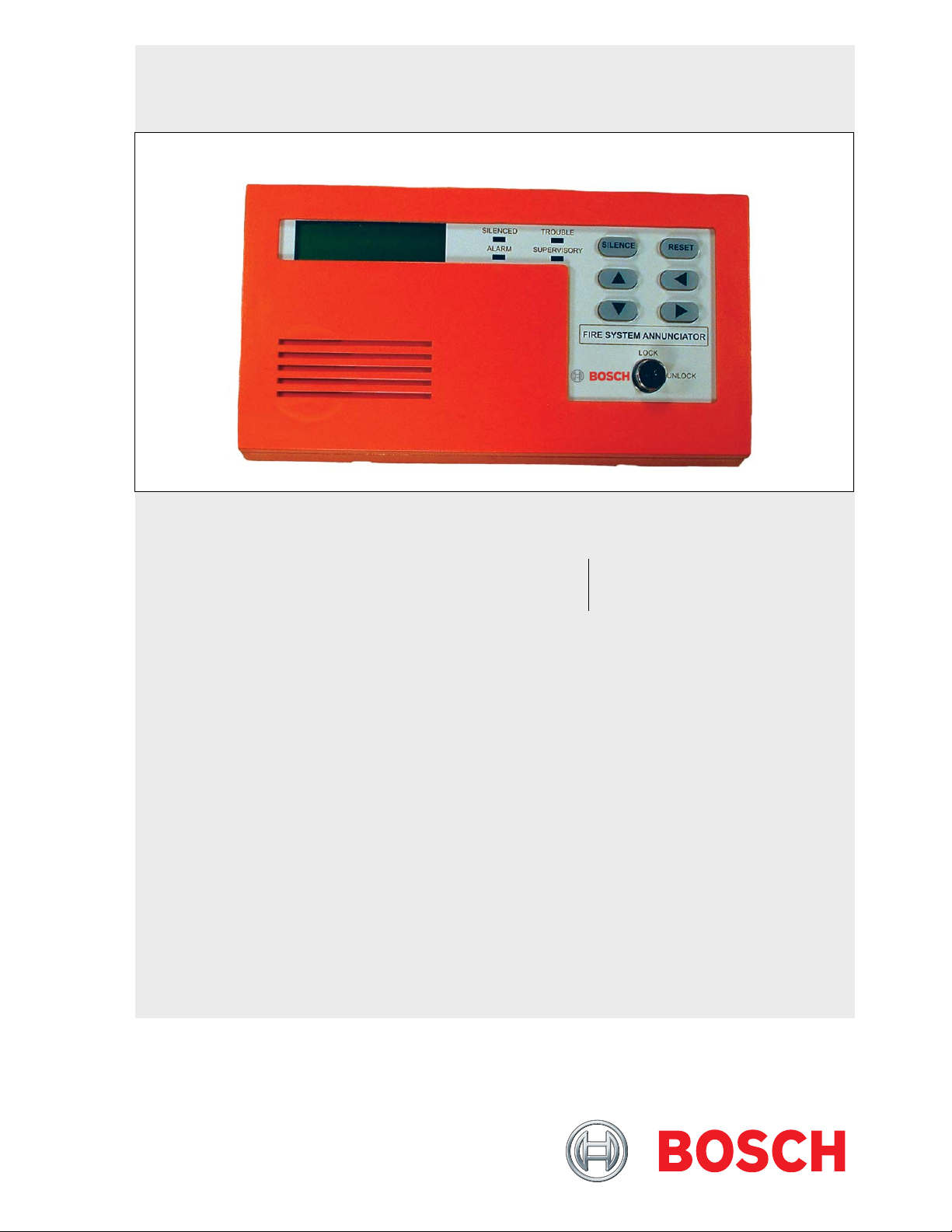
2.0 Device Description
The FMR-7036 is a four-wire LCD annunciator
keypad for the FPD-7024 Fire Alarm
Control/Communicator. It may be surface mounted
to a standard three-gang box or with the provided
mounting backplate.
Figure 1: FMR-7036 Fire Annunciator Keypad
SILENCED TROUBLE
ALARM SUPERVISORY
FIRE SY STEM ANNUNCIATOR
LOCK
UNLOCK
3.0 Installing the Reference
Card
A quick-reference card is provided and needs to be
installed in the receiving slot indicated in Figure 2.
The slot is located behind the mounting base
holding the circuit board.
The keypad should be mounted no higher than
shoulder height of the shortest person using the
system.
Remove the keypad’s cover.
Insert a small flathead screwdriver in each slot at the
bottom of the base. Press up, and pull the cover off.
4.1 Surface Mounting
Use the base as a template to mark the location of
the mounting holes (refer to Figure 3 on page 4 for
mounting hole location).
Provide an opening in the mounting surface for the
wiring.
Pre-start the mounting screws.
Do not secure the base at this point.
4.2 Electrical Box Mounting
Refer to Figure 3 on page 4 for the location of the
mounting holes.
Bosch Security Systems, Inc. | 9/08 | F01U010584-01 3
Page 4

FMR-7036 | Fire Annunciator Keypad | 5.0 Setting the FMR-7036 Address
Figure 3: Mounting Hole Locations
3
1
4
3
2
Back of FMR-7036 Keypad
2
3
1 - Holding tabs for reference guides
2 - Release tab
3 - Mounting Hole
4 - Wire Entrance
Do not secure the base at this point.
Figure 4: Inside View of FMR-7036 Keypad
7
6
5
5.0 Setting the FMR-7036 Address
Each keypad must have its address set
with its address pins. The keypads must
Figure 5: FMR-7036 Address Jumper Settings
Address 1
12 4 83567
Address 4
3
12 4 8
Address 7
12 4 8
Address 10
12 4 8
Address 13
12 4 8
Select the keypad address (1-14).
Place the shorting jumpers over the address pins as
shown in Figure 5.
also be programmed at the control panel.
Address 2
3567
12 4 8
Address 5
3567
3567
3567
3567
12 4 8
3567
Address 8
12 4 8
3567
Address 11
3567
12 4 8
Address 14
12 4 8
3567
Each option bus device must have its own
address, and each address can only
support one device.
Address 3
12 4 8
3567
Address 6
3567
12 4 8
Address 9
3567
12 4 8
Address 12
12 4 8
3567
Do not use
address 15
1
2
3
Red
Black
Green
Connector Cable Orientation
Yellow
1 - Wire Entrance
2 - Internal Sounder
3 - Mounting Hole
4 - Address jumper pins
5 - Control Keys
6 - Reset switch
7 - 2-line 16-character display
8 - Lock
8
1
4
8
3
6.0 Wiring the FMR-7036
Be sure all wiring is un-powered before
routing. Keypad wiring cannot be run with
smoke detector wiring, NAC wiring or MUX
loop wiring.
For the FPD-7024 FACP, the maximum allowed DC
current draw from the auxiliary power is 500 mA for
keypads. The maximum length of wire (all branches
added together) that can be connected to the option
bus terminals is 4000 ft (1,219 m).
The maximum length between any one device and
the panel terminals depends on the current drawn
on the branch that the device is on. The current
draw on a particular branch can be found by adding
together the individual current draws of each device
connected to the branch.
Refer to the FPD-7024 Installation Guide
(P/N: F01U008458) for detailed wire length
calculations.
4 Bosch Security Systems, Inc. | 9/08 | F01U010584-01
Page 5

FMR-7036 | Fire Annunciator Keypad | 7.0 FMR-7036 Programming
.
Up to three keypads may be used on any
single 1,000 ft. (305 m) run of #18 AWG
(1.2 mm) wire.
Bring the wiring through the wire entrance in the
keypad’s base. Connect the wiring to the keypad’s
connector. Refer to Figure 4 on page 4.
Secure the base.
Place the keypad cover onto the base. Make sure the
openings for the rubber keys line up and do not
crush the keys beneath the grid. Test each key to
ensure proper operation.
Figure 6: FMR-7036 Wire Connections
Red
R
Black
B
Consult your panel’s Reference
Green
Yellow
Guide for option bus wiring
G
Y
requirements.
8. Press [2] to select 2-AUTHORITY LEVEL.
9. Press [2] to select 2-MEDIUM.
10. Press [*] to exit programming mode.
11. Test all FMR-7036 functions.
A PIN is required for remote devices to
enable the use of the FMR-7036. To do
this, press [3] for PROG SYSTEM, [5] for
PIN REQUIRED?, [2] for REMOTE PIN and
[1] for YES. Press [*/Back] to exit the
programming mode.
7.2 FPD-7024 Remote Programming
1. Open a session of RAM IV.
2. Open the desired panel.
3. From the menu tree window, open SECURITY.
4. Select the user from the appropriate submenu.
5. Set the PIN in the appropriate column (9753).
6. Set the authority level in the appropriate
column (MEDIUM).
7. Download the changes/updates to the panel.
1
1 - FMR-7036 Wire Connector
7.0 FMR-7036 Programming
When the Silence or Reset keys on the FMR-7036
keypad are pressed, the keypad transmits a preprogrammed, hard coded key sequence of 9753,
followed by a control character that either silences
or resets the control.
In order for the FMR-7036 to work with the control,
a passcode of 9753 must be programmed into the
control. See the following instructions for specific
control panel programming.
7.1 FPD-7024 Local Programming
1. Enter the programming mode using the correct
programming passcode.
2. Select menu item 2-SECURITY.
3. Select menu item 1-PINS.
4. Select menu item 2-USER PINS.
5. Enter a User Number. Pick a user who has not
already been assigned a PIN.
6. Enter 9753 for the PIN.
7. Press [*] twice to view the SECURITY menu.
For more information regarding RAM IV,
see the RAM IV Operations Manual (P/N:
38849).
8.0 FMR-7036 Operation
There are six keys on the FMR-7036 used for
controlling annunciator and control panel operation:
Silence, Reset, and four scrolling buttons.
8.1 Silence
The Silence key is used to silence alarm and trouble
sounds at the annunciator, as well as NAC circuits
and sirens connected to the control panel, provided
the sounders are programmed for “SILENCEABLE”
(refer to the control panel’s programming guide for
information on NAC or alarm output configuration).
The Silence key will not remove the alarm condition
from the control. It only silences local annunciator
sounders as well as silenceable output devices.
Pressing the Silence key causes the FMR-7036 to
transmit a hard coded passcode of 9753 followed by
the Silence key normally found on the FMR-7036
keypad. The control must be programmed to accept
this code before the FMR-7036 will work (refer to
Section 7.0 on page 5 of this installation guide).
Bosch Security Systems, Inc. | 9/08 | F01U010584-01 5
Page 6

FMR-7036 | Fire Annunciator Keypad | 8.0 FMR-7036 Operation
8.2 Reset
The Reset key is used to reset the control panel after
an alarm has occurred. Any sounders or NACs that
are activated will silence, and smoke detector zones
will remove power briefly to reset detectors.
The Reset key causes the FMR-7036 to transmit a
hard coded passcode of 9753 followed by the Reset
key normally found on the FMR-7036. The control
must be programmed to accept this code before the
FMR-7036 will work (refer to Section 7.0 on page 5
of this installation guide).
8.3 Scrolling Buttons
The scrolling keys are used to view off-normal
conditions. The second line of the display will
alternate between the text of the event and the
instructions of which arrow button to press.
If the control panel is configured so that it requires
remote keypads to enter a pin, the bottom line of
the display will read Please Enter Pin.
To operate, unlock keyswitch and wait for the
second line to change to Use ACK/FUNC Key.
Press Silence, Reset, or ►.
If a pin is not required the display will show Use
ACK/FUNC Key. To operate, unlock keyswitch
and press Silence, Reset, or ►.
The ► is used as the Acknowledge button. When
pressed, the keypad and control panel peizo will silence
but the NACs will not be affected.
Pressing the ► key allows you to step through the
groups of off-normal conditions.
Pressing the ▲ or ▼ allows you to view details of an
off-normal condition within the group selected.
Pressing the ◄ key returns you to the main menu. If
pressed again, it releases control of the panel. If this
is not done, it will automatically time out in 3 min.
8.4 Keylock Switch
The Keylock Switch is an extra security feature built
into the FMR-7036 in accordance with NFPA 72
requirements. It can be used to lock out the
annunciator to prevent unwanted silence or resetting
of the control panel.
Turn the Keylock Switch to Lock to prevent
unwanted use of the Silence, Reset, and scrolling
buttons.
Turn the Keylock Switch to Unlock to restore
normal operation of the Silence, Reset, and scrolling
buttons.
8.5 Display
The two-line, 16-character display is capable of
showing all messages normally displayed on a FPD7024 or FMR-7033 keypad. All alarm and status
messages are included. In addition, there are four
LEDs for easy reading of annunciator status from a
distance. Refer to Table 1 for a description of each
LED’s function.
Table 1: FMR-7036 LED Functions
LED Color Function
Supervisory Yellow Turns on for any supervisory
Alarm Red Turns on for any fire alarm,
Trouble Yellow Turns on for any trouble
Silence Yellow Turns on whenever the Silence
8.6 Reset Switch
Use the Reset Switch to reset the keypad if the
display freezes or shows garbage, or if the Panel
Reset function does not resolve the problem.
Using the Keylock Switch to lockout the
FMR-7036 will prevent any user from
silencing or resetting alarms, including
emergency personnel such as the police or
fire department. Check with the local
Authority Having Jurisdiction before using
this feature.
The key may only be removed in the locked
position.
condition
including water flow
conditions at the control panel.
Read the LCD display on the
FMR-7036 for detailed Trouble
information.
button is activated.
6 Bosch Security Systems, Inc. | 9/08 | F01U010584-01
Page 7

.
9.0 Troubleshooting
Refer to Table 2 when troubleshooting the
FMR-7036.
Table 2: FMR-7036 Troubleshooting Tips
Keypad Notification Possible Causes
Continuous keypad sounder
PLUS ""System Fault""
display
Control panel does not
respond to keypad input.
The yellow and green wires
have been disconnected.
The keypad has not been
programmed at the control
panel. The control panel has
malfunctioned.
The keyswitch is in LOCK
position. The keypad's
address has not been set
with the jumper pins.
10.0 Specifications
Table 3: FMR-7036 Specifications
FMR-7036 | Fire Annunciator Keypad | 9.0 Troubleshooting
Operating Voltage 12 VDC Nominal from Option
Bus
Normal Standby
Current
Alarm Current 100 mA
Base Height 4.1 in (11.6 cm)
Base Width 8.2 in (20.8 cm)
Cover Height 4.3 in (10.9 cm)
Cover Width 8.1 in (20.6 cm)
Environment Use Indoor/Dry
Operating Temperature +32° to 120°F (0° to +49°C)
Relative Humidity 93%
Listings UL864, FM
Wiring Supervised Communication
80 mA
Circuit
Bosch Security Systems, Inc. | 9/08 | F01U010584-01 7
Page 8

Bosch Security Systems, Inc.
130 Perinton Parkway
Fairport, NY 14450-9199
(800) 289-0096
www.boschsecurity.com
© 2008 Bosch Security Systems, Inc.
F01U010584-01
 Loading...