

BOSCH SECURITY SYSTEMS, INC.
130 Perinton Parkway
Fairport, NY 14450 USA
II. MOUNTING THE DETECTOR
The sampling tubes may be ordered to a desired length or ordered in one of 3 standard lengths and cut
per requirements. The intake sampling tube consists of a piece of steel piping with a series of holes
drilled the entire length of the tube and should extend the entire width of the duct. The holes must be
facing into the air flow (see Figure 2). The exhaust tube consists of a piece of steel piping
approximately 7-1/2" long.
1. Remove paper backing from mounting template AP 121 (packaged in installation kit) and affix to
duct at desired location.
2. Using template as a guide, drill 4 mounting holes (3/32" diameter) for duct mounting screws (4 #12
x 1/2" sheet metal screws packaged in installation kit). Drill or punch holes for sampling tubes in air
ducts (1-3/8" diameter), using template as a guide. Clean all holes.
Duct Smoke Detector Location Requirements:
detectors should not be mounted in areas of extreme high or low temperatures, in
areas where high humidity exist, or in areas where duct air may contain gases or
excess dust. The duct detector should, when possible, be located a minimum of six
duct widths downstream from a source of turbulence (bends, inlets, or deflection
plates). At these locations, air flow is less turbulent and the air/smoke mixture
should be more homogenous.Refer to NFPA 90A, 72, and 101 for more information.
See Figure 1A and 1B.
Exception: Where it is physically impossible to locate the duct detector accordingly,
the duct detector can be positioned closer than six duct widths, but as far as
possible from inlets, bends, or deflection plates .
*These products are compatible exclusively with fire alarm control panels that utilize BOSCH's protocol, DCP.
These are Installation Instructions (DWG.# HA-06-184) for the Analog Duct Housing customized as follows:
FAD-325 Duct Housing with the FAD-325-DH Analog Photoelectric Smoke Sensor*
FAD-325-V2F Duct Housing with the FAD-325-V2F-DH Analog Photoelectric Smoke Sensor*
FAD-325-R Duct Housing with the FAD-325-DH Analog Photoelectric Smoke Sensor & Relays*
FAD-325-V2F-R Duct Housing with the FAD-325-V2F-DH Analog Photoelectric Smoke Sensor & Relays*
INSTALLATION INSTRUCTIONS FOR THE DUCT SMOKE DETECTOR
A. DUCT PREPARATION
The Duct Detectors are designed for use in ducts where the air velocities are from 300 to 4000 feet per
minute. Verify this by checking specifications of installation and if necessary, use an Alnor Model
6000P velocity meter (or equivalent) to check the air velocity. See Figure 2 for sampling tube
orientation to air flow direction.
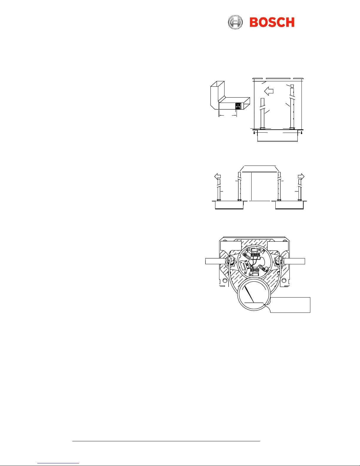
SET
SCREW
CONNECTORS
FIG URE 1B: DUCT HOUSING MOUNTING
TOP OF DUCT HOUSING
DUCT MOUNTING
SCREWS
FIGURE 2 SAMPLING TUBE ORIENTAT ION
INSERT STOPPER AT THIS END OF
INTAKE TUBE
TOP OF DUCT HOUSING
EXHAUST
TUBE
AIR FLOW
INTAKE
TUBE
INTAKE
SAMPLING
TUBE TO BE
SUPPORTED
WHERE THE
WIDTH OF
THE DUCT IS
GREATER
THAN 3 FEET.
WIDTH OF DUCT
TOP OF DUCT HOUSING
EXHAUST
TUBE
INTAKE
TUBE
AIR FLOW
EXHAUST
TUBE
Bend or
Other
Obstruction
6 Duct
Widths
Minimum
FIGURE 1A
TEMPLATE
AIR FLOW
FOR THIS
ILLUSTRATION
INTAKE
SAMPLING
TUBE
STOPPER
1. With power source de-energized and the smoke detector not installed, wire all connections per engineering drawings.
Refer to the applicable figures below depending on your duct housing model number.
2. With all wiring in place, install the detector head.
3. Energize the duct detector.
Wiring must conform to applicable local codes, ordinances and regulations covering these types of devices. Wire the detectors according to the engineering drawings for the
particular job requirements. These detectors are not intended for open area protection, nor should they be used for open air protection. Refer to NFPA 90A and NFPA 72 for
general and additional information on Duct Smoke Detectors concerning operation and installation. Terminals are suitable for up to #14 gauge wire.
To verify proper sampling of air, use a Dwyer Model 4000 differential pressure gauge (or equivalent).
See Figure 3 for gauge connections. The pressure differential between input sampling tube and
exhaust tube should be greater than 0.01" of water and less than 1.2" of water.
Move duct housing/sampling tube assembly to desired location. Use 4 mounting screws (4 #12 x 1/2" sheet
metal screws, packaged in installation kit) to secure the housing to the air duct.
1. Sampling tube connectors are equipped with set screws, which allow the tubes to be mounted
only in directions shown in Figure 2. Establish proper orientation considering airflow direction.
2. Insert intake and exhaust tubes into connectors, align set screw to set screw hole in tubes and
tighten firmly.
1. Cut the intake sampling tube to the desired length.
2. Firmly insert the stopper (packaged in installation kit) in the end of the INTAKE sampling tube.
INTAKE SAMPLING TUBES STANDARD LENGTHS:
III. ELECTRICAL INSTALLATION
FIG. 3 AIR SAMPLING
VERIFICATION
For duct widths of 1.0' to 2.5'
For duct widths of 2.5' to 5.0'
For duct widths of 5.0' to 10.0'
EXHAUST TUBE
HOLE &
CONNECTOR
LOW PRESSURE
SIDE
FAA-325-2.5
FAA-325-5
FAA-325-10
DWYER #4000 DIFFERENTIAL
PRESSURE GAUGE (OR
EQUIVALENT) WITH TUBING
AND SIZE 0 RUBBER STOPPERS
(HA PART# 0700-01118).
HIGH PRESSURE
SIDE
INTAKE TUBE
HOLE &
CONNECTOR
Note: All duct detector models can be tested with actual smoke. Remove the duct detector cover. Test the detector head by lighting a piece of cotton
clothesline. and placing it approximately 3 inches from the detector head. Blow across the lit end of the clothesline toward the detector. The LEDs on the
detector should illuminate within one minute. After performing this test sequence, reinstall the duct detector cover.
These duct sensors are analog addressable and can be calibrated by a U.L. Listed analog control panel. See the FACP Installation
Instructions for specific directions.
Models FAD-325/FAD-325-V2F/ FAD-325-R and FAD-325-V2F-R
BOSCH Security Systems, Inc. * FAD-325 Installation Instructions (HA-06-184. P/N 1700-11140 Page 1 of 2)
Specifications subject to change without notice. * February 2017
B. VERIFY AIR FLOW AND DIRECTION
C. SAMPLING TUBE ASSEMBLY (See Figure 2)
D. MOUNT SAMPLING TUBES (See Figure 2)
E. MOUNT THE DUCT HOUSING (See Figure 1B & 2)
F. VERIFY AIR SAMPLING (See Figure 3)
A. GENERAL INFORMATION
B. DETECTOR WIRING
I. LOCATION REQUIREMENTS
To prevent false alarms the
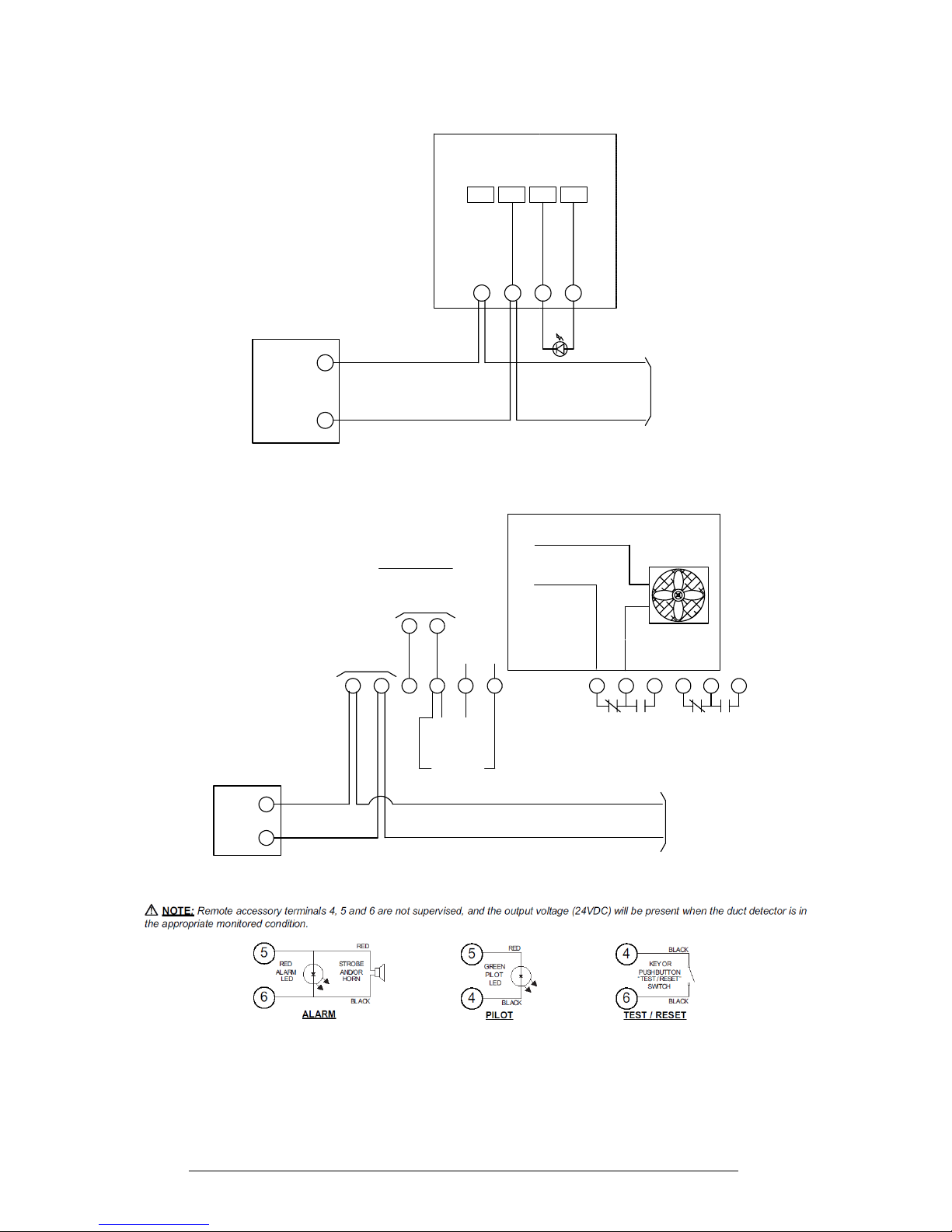
Terminate Remote Accessories as indicated above (if required).
This is not a self-contained stand alone detector.
A U.L. Listed Analog Addressable Fire System is required.
ANALOG ADDRESSABLE
FIELD LOOP WIRING
REMOTE TEST
SWITCH
(Test function only. does not reset.)
REMOTE
ALARM
LED
6
III. ELECTRICAL INSTALLATION, continued
OBSERVE POLARITY
INPUT VOLTAGE
24 V.D.C.
S (+)
SC (-)
UL LISTED
CONTROL PANEL
A.A.
CONTROL
PANEL
ADDRESSABLE
LOOP
1 2
+
-
REMOTE
PILOT LED
10 mA Standby
55mA Alarm
3 4
+
-
+
5
FAD-325-R/FAD-325-V2F-R WIRING DIAGRAM
FAD-325/FAD-325-V2F WIRING DIAGRAM
The FAD-325, FAD-325-V2F, FAD-325-R and
FAD-325-V2F-R are not self-contained sensors.
This product is compatible only with fire alarm
control panels that utilize BOSCH's Digital
Communications Protocol, DCP.
For example the FPA-1000 Family of Control Panels
D. WIRING DIAGRAMS, continued
UL LISTED
CONTROL PANEL
LOOP INTERFACE
S (+)
SC (-)
SUPPLY VOLTAGE
TO NEXT SENSOR
OR RETURN
TO CONTROL PANEL
ALARM CONTACTS
10.0A @ 250VAC
NC
ALARM CONTACTS
10.0A @ 250VAC
NONC
C
7 8 9 10
NO
C
1211
THE D304 REMOTE ALARM LED
WIRING MUST HAVE POLARITY AS
SHOWN 24 VDC (8mA MAX.)
-R +RL2L1
FAN SHUTDOWN EXAMPLE
421 3
(-)
FAN
TO NEXT
SENSOR
(+)
FAD-325-DH/FAD-325-V2F-DH
ANALOG SENSOR
* Remote common alarm indication, remote pilot indication, remote common reset, common shutdown and common visual indication.
* Common fault indication (when green pilot LED is extinguished) cannot be achieved on the FAD-325 Duct Units. Individual Remote
Pilot LED's must be installed to monitor detector head or power source removal for each unit.
* In the event of an alarm, the detector head and duct unit alarm (Red) LED's will be illuminated. All remaining duct unit alarm LED's will
not be illuminated. All remote alarm LED's fitted to the duct units will be illuminated when any of the units go into alarm. Only the duct
unit in alarm will permit resetting of the system from the built in test/reset switch on that particular duct unit.
* A common Remote reset switch will reset all detectors.
Common functions include one or all of the following:
BOSCH Security Systems, Inc. * FAD-325 Installation Instructions (HA-06-184. P/N 1700-11140 Page 2 of 2)
Specifications subject to change without notice. * February 2017
The Bosch D304/D305 Remote Duct Annunciator and the Bosch
FAD-325-R/FAD-325-V2F-R Duct Detectors are compatible when
wired as the following.
STANDBY 350µA
ALARM 800µA
 Loading...