

Bosch FAA-500, FAA-500-R Installation Instructions Manual
Installationshinweis / Installation Instructions
(FAA-500-R)
(FAA-500-R)
FAA-500, FAA-500-R - Meldersockel / Detector bases
0V
+V
sw/bk sw/bk
FAA-500(-R)
rt/r rt/r
BMZ /
FACP
b2
ge/y
nächster Melder/ next detector
LSN a1/a2
LSN b1
MPA = Melderparallelanzeige/Remote Fire Alarm Display
ws/w
gn/g
nicht beim Relaissockel / not for relay bases
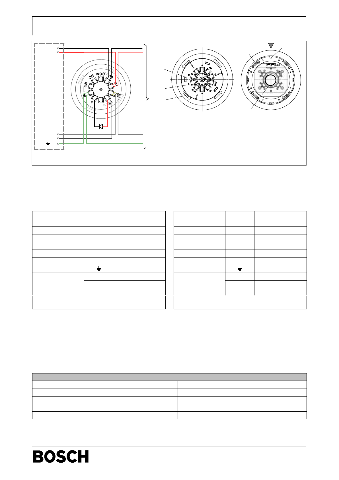
Anschaltung
Verdrahten Sie den Sockel LSN gemäß der Beschriftung im
äußeren Ring (2), (innerer Ring: GLT-Sockel).
. Die Halterungen für Kabelbinder (1) können zum
Fixieren des Sockels während des Verdrahtens genutzt
werden.
Anschluss
Spannung - * 0 V schwarz (sw)
Spannung + * + V rot (rt)
LSN a in/out a1/a2 weiß (ws)
LSN b in b1 gelb (ge)
LSN b out b2 gelb (ge)
Indikatorausgang c
Abschirmung (grün [gn])
Relaisausgänge
-
-
* Klemmen zum Durchschleifen der Versorgungsspannung für andere LSN-Elemente
MPA
ge/y
ws/w
gn/g
Deutsch
Klemme Draht
NO
NC
COM
4
6
1
2
3
7
5
(7) Feder für Meldereinbau in Zwischendecken
Bei Meldereinbau in Beton- oder Holzdecken muss die
Spezialfeder FAA-500-SPRING (Sachnr. F.01U510.028,
Liefereinheit 10 Stck., rote Markierung) eingesetzt werden.
(7) Spring for detector mounting in false ceiling panels
(7) Spring for detector mounting in false ceiling panels
For concrete and wooden ceilings, replace with
For concrete and wooden ceilings, replace with
FAA-500-SPRING (part nr. F.01U510.028, delivery unit
FAA-500-SPRING (part nr. F.01U510.028, delivery unit
10 pcs., red marking).
10 pcs., red marking).
English
Wiring
Wire the LSN bases according to the lettering on the outer
ring (2), (inner ring: conventional technology).
. During cabling, the holders for cable t ies (1) can be used t o
fix the base.
Connection
Terminal Wire
Voltage - * 0 V black (bk)
Voltage + * + V red (r)
LSN a in/out a1/a2 white (w)
LSN b in b1 yellow (y)
LSN b out b2 yellow (y)
Indicator output c
Shielding green (g)
NO
Relay
-
-
NC
COM
* Terminals for interconnecting all bases with voltage
supply for other LSN elements
Montage
1. Setzen Sie den Sockel so in die Hohlraumdose ein, dass
die dreieckige Markierung am Außenrand der Hohlraumdose (4) mit der einfachen Führungsnut (5) am Sockel
übereinstimmt.
2. Drehen Sie den Sockel, bis die Befestigungsschrauben
in der Mitte der Langschlitze (6) sind.
3. Justieren Sie die Sockel um diese Position, bis sie in einer Linie erscheinen.
Mounting
1. Place the base in the ceiling mount back box so that the
triangular mark (4) on the outer rim of the back box
matches with the single guideway (5).
2. Turn the base until the fastening screws are in the middle
of the long slit (6).
3. Slightly turn each base until the bases align in one direction.
4. Tighten the four screws.
4. Drehen Sie die vier Schrauben fest.
Technische Daten / Technical Data
Meldersockeltyp / Base type FAA-500 FAA-500-R
Stromaufnahme / Current consumption - 0,2 mA
Relaiskontakt-Belastbarkeit / Contact load - 1 A, 30 V DC
Kabelquerschnitt / Wire gauge 0,3 mm2 - 3,3 mm2 (22 AWG - 12 AWG)
Sachnummer / Part number 4.998.151.297 4.998.151.299
BOSCH Sicherheitssysteme GmbH
Robert-Koch-Str. 100
info.service@de.bosch.com
www.boschsecuritysystems.com
D-85521 Ottobrunn
610- F.01U.000.615 / A2
1 / 4
de/en/fr/it/es/pt/nl/tr
ST/PMF/zab
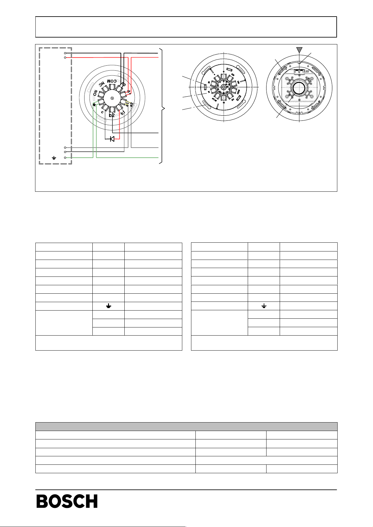
Instruction de mise en place / Avviso d’Installazione
(FAA-500-R)
(FAA-500-R)
FAA-500, FAA-500-R - Socles de détecteur / Basi rivelatore
0V
+V
n/n n/n
FAA-500(-R)
r/r r/r
FACP /
FACP
j/g
LSN a1/a2
LSN b1
MPA = Affichage d’alarme incendie à distance
b/b
v/v
(pas pour le socle à relais)/
Indicatore in parallelo di sensore
(non per base relè)
MPA
j/g
b/b
v/v
détecteur suivant / prossimo sensore
(7) Elemento di fissaggio per il montaggio del rivelatore sui
pannelli di un falso soffitto
In caso di soffitti in cemento e in legno, sostituire con l’elemento
di fissaggio FAA-500 (N. prodotto F.01U510.028, unità di
fornitura da 10 pz., contrassegno rosso).
Français
Câblage
Procédez au câblage des socles LSN en fonction des indications sur l a bague extérieure ( 2), (bague intérieure : t echnol ogie
traditionnel l e).
. Pendant le câblage, vous pouvez utiliser les supports
des attaches de câbles (1) pour fixer le socle.
Connexion
Tension - * 0 V noir (n)
Tension + * + V rouge (r)
Entrée/sortie LSN a a1/a2 blanc (b)
Entrée LSN b b1 jaune (j)
Sortie LSN b b2 jaune (j)
Sortie d’indicateur c
Blindage vert (v)
Relais
-
-
* Bornes d’interconnexion de tous les socles avec alimentation en tension pour autres éléments LSN
Borne Fil
NO
NF
COM
4
6
1
2
3
7
5
(7) Ressort pour montage du détecteur dans des panneaux
de faux plafonds
Pour les plafonds en béton et en bois, utilisez plutôt le
Ressort FAA-500 (réf. F.01U510.028, livraison par 10 pcs.,
marquage rouge).
Italiano
Cablaggio
Cablare le basi LSN secondo le indicazioni delle lettere sull’anello esterno (2), (anel lo interno: tecnologia tradizionale).
. Durante il cablaggio, il supporto per le fascette fermacavi
(1) può essere utilizzato per fissare la base.
Connessione
Tensione - * 0 V nero (n)
Tensione + * + V rosso (r)
LSN a in/out a1/a2 bianco (b)
LSN b in b1 giallo (g)
LSN b out b2 giallo (g)
Uscita indicatore c
Shielding verde (v)
Relè
-
-
* Terminali per l’interconnessione di tutte le basi per l’alimentazione di altri elementi LSN.
Terminale Cavo
NO
NC
COM
Montage
1. Placez le socle dans le boîtier arrière pour montage au
plafond de manière à ce que le repère triangulaire (4) sur
le bord extérieur du boîtier arrière coïncide avec la rainure de guidage unique (5).
2. Tournez le socle jusqu’à ce que les vis de fixation se
trouvent au centre de la longue fente (6).
3. Tournez légèrement chaque socle jusqu’à ce que tous
les socles soient alignés dans le même sens.
Montaggio
1. Posizionare la scatola a incasso in modo che il contrassegno triangolare (4) sul margine esterno della scatola a
incasso corrisponda alla scanalatura della guida.
2. Ruotare la base finché le viti di fissaggio non si trovano
al centro della scanalatura lunga (6).
3. Ruotare leggermente ogni base fino ad allinearle in una
direzione.
4. Stringere le quattro viti.
4. Serrez les quatre vis.
Données techniques / Dati tecnici
Type de socle / Tipo base FAA-500 FAA-500-R
Consommation de courant / Consumo di corrente - 0,2 mA
Charge des contacts / Carico contatto - 1 A, 30 V c.c. / DC
Section des câbles / Diametro del cavo 0,3 mm2 - 3,3 mm2 (22 AWG - 12 AWG)
Code produit / Codice Prodotto 4.998.151.297 4.998.151.299
610- F.01U.000.615 / A2
2 / 4
de/en/fr/it/es/pt/nl/tr
ST/PMF/zab
 Loading...