

Bosch DVR1EP08, DVR1EP16 Instruction Manual
Instruction Manual
EN Single Channel,
Color Digital Video
Recorder
Applicable Models:
DVR1EP08, DVR1EP16,
DVR1EP32, and DVR1EP32A
DVR1 Series

Important Safeguards
1. Read, Follow, and Retain Instructions - All safety and
operating instructions should be read and followed before
operating the unit. Retain instructions for future reference.
2. Heed Warnings – Adhere to all warnings on the unit and
in the operating instructions.
3. Attachments - Attachments not recommended by the
product manufacturer should not be used, as they may
cause hazards.
4. Installation Cautions - Do not place this unit on an
unstable stand, tripod, bracket, or mount. The unit may
fall, causing serious injury to a person and serious damage
to the unit. Use only manufacturer-recommended
accessories, or those sold with the product. Mount the unit
per the manufacturer's instructions. Appliance and cart
combination should be moved with care. Quick stops,
excessive force, or uneven surfaces may cause the
appliance and cart combination to overturn.
5. Cleaning - Unplug the unit from the outlet before
cleaning. Follow any instructions provided with the unit.
Generally, using a damp cloth for cleaning is sufficient. Do
not use liquid cleaners or aerosol cleaners.
6. Servicing - Do not attempt to service this unit yourself.
Opening or removing covers may expose you to
dangerous voltage or other hazards. Refer all servicing to
qualified service personnel.
7. Damage Requiring Service - Unplug the unit from the
main AC power source and refer servicing to qualified
service personnel under the following conditions:
•When the power supply cord or plug is damaged.
• If liquid has been spilled or an object has fallen into the
unit.
• If the unit has been exposed to water and/or inclement
weather (rain, snow, etc.).
• If the unit does not operate normally, when following
the operating instructions. Adjust only those controls
specified in the operating instructions. Improper
adjustment of other controls may result in damage, and
require extensive work by a qualified technician to
restore the unit to normal operation.
• If the unit has been dropped or the cabinet damaged.
• If the unit exhibits a distinct change in performance, this
indicates that service is needed.
8. Replacement Parts - When replacement parts are
required, the service technician should use replacement
parts specified by the manufacturer, or that have the same
characteristics as the original part. Unauthorized
substitutions may result in fire, electrical shock, or other
hazards.
9. Safety Check - Upon completion of servicing or repairs to
the unit, ask the service technician to perform safety
checks to ensure proper operating condition.
10. Power Sources - Operate the unit only from the type of
power source indicated on the label. If unsure of the type
of power supply to use, contact your dealer or local power
company.
• For units intended to operate from battery power, refer
to the operating instructions.
• For units intended to operate with External Power
Supplies, use only the recommended approved power
supplies.
• For units intended to operate with a limited power
source, this power source must comply with EN60950.
Substitutions may damage the unit or cause fire or
shock.
• For units intended to operate at 24VAC, normal input
voltage is 24VAC. Voltage applied to the unit's power
input should not exceed 30VAC.
User-supplied wiring, from the 24VAC supply to unit,
must be in compliance with electrical codes (Class 2
power levels). Do not ground the 24VAC supply at the
terminals or at the unit's power supply terminals.
11. Coax Grounding - If an outside cable system is connected
to the unit, ensure that the cable system is grounded.
U.S.A. models only--Section 810 of the National Electrical
Code, ANSI/NFPA No.70, provides information regarding
proper grounding of the mount and supporting structure,
grounding of the coax to a discharge unit, size of
grounding conductors, location of discharge unit,
connection to grounding electrodes, and requirements for
the grounding electrode.
12. Grounding or Polarization - This unit may be equipped
with a polarized alternating current line plug (a plug with
one blade wider than the other). This safety feature allows
the plug to fit into the power outlet in only one way. If
unable to insert the plug fully into the outlet, try reversing
the plug. If the plug still fails to fit, contact an electrician to
arrange replacement of the obsolete outlet. Do not defeat
the safety purpose of the polarized plug.
Alternately, this unit may be equipped with a
3-wire grounding plug (a plug with a third pin, for
grounding). This safety feature allows the plug to fit into a
grounding power outlet only. If unable to insert the plug
into the outlet, contact an electrician to arrange
replacement of the obsolete outlet. Do not defeat the safety
purpose of the grounding plug.
13. Lightning - For added protection during a lightning storm,
or when this unit is left unattended and unused for long
periods of time, unplug the unit from the wall outlet and
disconnect the cable system. This will prevent damage to
the unit due to lightning and power line surges.
2
3
For Indoor Product
1. Water and Moisture - Do not use this unit near
water - for example, in a wet basement, in an
unprotected outdoor installation, or in any area
classified as a wet location.
2. Object and Liquid Entry - Never push objects of
any kind into this unit through openings, as they
may touch dangerous voltage points or short out
parts that could result in a fire or electrical shock.
Never spill liquid of any kind on the unit.
3. Power Cord and Power Cord Protection - For
units intended to operate with 230VAC, 50Hz,
the input and output power cord must comply
with the latest versions of IEC Publication 227 or
IEC Publication 245.
Power supply cords should be routed so they are
not likely to be walked on or pinched. Pay
particular attention to location of cords and plugs,
convenience receptacles, and the point of exit
from the appliance.
4. Overloading - Do not overload outlets and
extension cords; this can result in a risk of fire or
electrical shock.
For Outdoor Product
Power Lines - An outdoor system should not be
located in the vicinity of overhead power lines,
electric lights, or power circuits, or where it may
contact such power lines or circuits. When
installing an outdoor system, extreme care should
be taken to keep from touching power lines or
circuits, as this contact might be fatal. U.S.A.
models only - refer to the National Electrical
Code Article 820 regarding installation of CATV
systems.
For Rack-mount Product
1. Ventilation - This unit should not be placed in a
built-in installation or rack, unless proper
ventilation is provided, or the manufacturer’s
instructions have been adhered to. The
equipment must not exceed its maximum
operating temperature requirements.
2. Mechanical Loading - Mounting of the
equipment in a rack shall be such that a
hazardous condition is not achieved due to
uneven mechanical loading.
WARNING:
Electrostatic-sensitive device. Use
proper CMOS/MOSFET handling
precautions to avoid electrostatic
discharge.
NOTE: Grounded wrist straps must be worn and proper ESD
safety precautions observed when handling the electrostaticsensitive printed circuit boards.
ATTENTION
OBSERVE PRECAUTIONS
FOR HANDLING
ELECTROSTATIC SENSITIVE
DEVICES
Safety Precautions
Attention: Installation should be performed by
qualified service personnel only in accordance
with the National Electrical Code or applicable
local codes.
Power Disconnect. Units with or without
ON-OFF switches have power supplied to the
unit whenever the power cord is inserted into the
power source; however, the unit is operational
only when the ON-OFF switch is in the ON
position. The power cord is the main power
disconnect for all units.
CAUTION: TO REDUCE THE RISK OF
ELECTRIC SHOCK, DO NOT REMOVE COVER
(OR BACK). NO USER SERVICEABLE PARTS
INSIDE. REFER SERVICING TO QUALIFIED
SERVICE PERSONNEL.
This symbol indicates the presence of
uninsulated “dangerous voltage” within the
product’s enclosure. This may constitute a
risk of electric shock.
The user should consult the operating and
maintenance (servicing) instructions in the
literature accompanying the appliance.
CAUTION: Lithium Battery
Danger of explosion if battery is incorrectly replaced.
Replace only with the same or equivalent type
recommended by the manufacturer. Dispose of used
batteries according to the battery manufacturer’s
instructions.
4
Sicherheitshinweise
Achtung! Die Installation sollte nur von qualifiziertem
Kundendienstpersonal gemäß jeweils zutreffender
Elektrovorschriften ausgeführt werden.
Unterbrechung des Netzanschlusses. Geräte mit oder ohne
Netzschalter haben Spannung am Gerät anliegen, sobald der
Netzstecker in die Steckdose gesteckt wird. Das Gerät ist jedoch
nur betriebsbereit, wenn der Netzschalter (EIN/AUS) auf EIN
steht. Wenn das Netzkabel aus der Steckdose gezogen wird, ist
die Spannungszuführung zum Gerät vollkommen unterbrochen.
VORSICHT: UM EINEN ELEKTRISCHEN SCHLAG ZU
VERMEIDEN, IST DIE ABDECKUNG (ODER RÜCKSEITE) NICHT
ZU ENTFERNEN. ES BEFINDEN SICH KEINE TEILE IN DIESEM
BEREICH, DIE VOM BENUTZER GEWARTET WERDEN KÖNNEN.
LASSEN SIE WARTUNGSARBEITEN NUR VON QUALIFIZIERTEM
WARTUNGSPERSONAL AUSFÜHREN.
Das Symbol macht auf nicht isolierte „gefährliche Spannung"
im Gehäuse aufmerksam. Dies kann zu einem elektrischen
Schlag führen.
Der Benutzer sollte sich ausführlich über Anweisungen für
die Bedienung und Instandhaltung (Wartung) in den
begleitenden Unterlagen informieren.
Precauciones de Seguridad
Atención: la instalación la debe realizar únicamente personal
cualificado de conformidad con el National Electric Code o las
normas aplicables en su país.
Desconexión de la alimentación. Las unidades con o sin
interruptores de encendido/apagado reciben alimentación
eléctrica siempre que el cable de alimentación esté conectado a
la fuente de alimentación. Sin embargo, la unidad sólo funciona
cuando el interruptor está en la posición de encendido. El cable
de alimentación es la principal fuente de desconexión de todas
las unidades.
PRECAUCIÓN: PARA DISMINUIR EL RIESGO DE DESCARGA
ELÉCTRICA, NO RETIRE LA CUBIERTA (NI LA PARTE
POSTERIOR). NO EXISTEN PIEZAS DE RECAMBIO EN EL
INTERIOR DEL EQUIPO. EL PERSONAL DE SERVICIO
CUALIFICADO SE ENCARGA DE REALIZAR LAS
REPARACIONES.
Este símbolo indica que existen puntos de tensión peligrosos
sin aislamiento dentro de la cubierta de la unidad. Estos
puntos pueden constituir un riesgo de descarga eléctrica.
El usuario debe consultar las instrucciones de funcionamiento y
mantenimiento (reparación) en la documentación que se
suministra con el aparato.
Sécurité
Attention : l'installation doit exclusivement être réalisée par du
personnel qualifié, conformément au code national d'électricité
américain (NEC) ou au code d'électricité local en vigueur.
Coupure de l'alimentation. Qu'ils soient pourvus ou non d'un
commutateur ON/OFF, tous les appareils reçoivent de l'énergie une
fois le cordon branché sur la source d'alimentation. Toutefois,
l'appareil ne fonctionne réellement que lorsque
le commutateur est réglé sur ON. Le débranchement du cordon
d'alimentation permet de couper l'alimentation des appareils.
ATTENTION : POUR ÉVITER TOUT RISQUE D'ÉLECTROCUTION,
N'ESSAYEZ PAS DE RETIRER LE CAPOT (OU LE PANNEAU
ARRIÈRE). CET APPAREIL NE CONTIENT AUCUN COMPOSANT
SUSCEPTIBLE D'ÊTRE RÉPARÉ PAR L'UTILISATEUR. CONFIEZ
LA RÉPARATION DE L'APPAREIL À DU PERSONNEL QUALIFIÉ.
Ce symbole signale que le produit renferme une « tension
potentiellement dangereuse » non isolée susceptible de
provoquer une électrocution.
Ce symbole invite l'utilisateur à consulter les instructions
d'utilisation et d'entretien (dépannage) reprises dans la
documentation qui accompagne l'appareil.
FCC & ICES INFORMATION
(U.S.A. and Canadian Models Only)
This device complies with part 15 of the FCC Rules. Operation is
subject to the following two conditions:
(1) This device may not cause harmful interference, and
(2) This device must accept any interference received,
including interference that may cause undesired
operation.
NOTE: This equipment has been tested and found to comply
with the limits for a Class A digital device, pursuant to Part 15 of
the FCC Rules and ICES-003 of Industry Canada. These limits
are designed to provide reasonable protection against harmful
interference when the equipment is operated in a commercial
environment. This equipment generates, uses and radiates radio
frequency energy, and if not installed and used in accordance
with the instruction manual, may cause harmful interference to
radio communications. Operation of this equipment in a
residential area is likely to cause harmful interference, in which
case the user will be required to correct the interference at his
expense.
Intentional or unintentional changes or modifications, not
expressly approved by the party responsible for compliance, shall
not be made. Any such changes or modifications could void the
user’s authority to operate the equipment. If necessary, the user
should consult the dealer or an experienced radio/television
technician for corrective action. The user may find the following
booklet, prepared by the Federal Communications Commission,
helpful: How to Identify and Resolve Radio-TV Interference
Problems. This booklet is available from the U.S. Government
Printing Office, Washington, DC 20402, Stock No. 004-00000345-4.
WARNING: This is a Class A product. In a domestic
environment, this product may cause radio interference,
in which case, the user may be required to take adequate
measures.
5
Veiligheidsmaatregelen
Attentie: het apparaat mag alleen door gekwalificeerd personeel
worden geïnstalleerd. De installatie dient in overeenstemming
met de nationale elektrische richtlijnen of de van toepassing
zijnde lokale richtlijnen te worden uitgevoerd.
Spanning uitschakelen. Apparatuur met of zonder
aan-uitschakelaar staat onder spanning zolang de stekker is
aangesloten op de wandcontactdoos. De apparatuur is uitsluitend
in werking als de aan-uitschakelaar aan staat. Het netsnoer is de
"hoofdschakelaar" voor alle apparatuur.
VOORZICHTIG: OPEN DE BEHUIZING OF DE ACHTERKANT
VAN HET APPARAAT NIET. ZO VERMINDERT U HET RISICO
OP ELEKTRISCHE SCHOKKEN. IN HET APPARAAT
BEVINDEN ZICH GEEN ONDERDELEN DIE U ZELF KUNT
REPAREREN. LAAT SERVICE EN ONDERHOUD UITVOEREN
DOOR GEKWALIFICEERD PERSONEEL.
Dit symbool geeft aan dat er binnen in het apparaat
ongeïsoleerde, gevaarlijke spanning aanwezig is die mogelijk
elektrische schokken kan veroorzaken.
De gebruiker dient de bedienings- en onderhoudsvoorschriften
te raadplegen in de documentatie die werd meegeleverd met
het apparaat.
Sicurezza
Attenzione: l'installazione deve essere effettuata esclusivamente
da personale tecnico qualificato in conformità con il National
Electrical Code o con le normative locali vigenti.
Scollegamento dell'alimentazione. Le unità dotate o sprovviste di
interruttori ON-OFF vengono alimentate quando si inserisce il
cavo nella presa dell'alimentazione. L'unità è tuttavia in funzione
solo quando l'interruttore ON-OFF si trova nella posizione ON. Il
cavo di alimentazione costituisce il dispositivo di scollegamento
dell'alimentazione principale per tutte le unità.
ATTENZIONE: PER RIDURRE IL RISCHIO DI SCOSSE
ELETTRICHE NON RIMUOVERE LA COPERTURA (O IL
PANNELLO POSTERIORE). L'UNITÀ NON CONTIENE
COMPONENTI INTERNI RIPARABILI DALL'UTENTE. PER
QUALSIASI INTERVENTO, RIVOLGERSI A PERSONALE
TECNICO QUALIFICATO.
Questo simbolo indica la presenza di "tensione pericolosa" non
isolata all'interno del contenitore del prodotto. Ciò comporta
un potenziale rischio di scosse elettriche.
Si consiglia di consultare le istruzioni operative e di
manutenzione (interventi tecnici) contenute nella
documentazione fornita con il dispositivo.
Medidas de Segurança
Atenção: a instalação deve ser executada apenas por técnicos
qualificados da assistência, de acordo com o código eléctrico
nacional ou os códigos locais aplicáveis.
Corte de corrente. As unidades com ou sem interruptores
ON-OFF (ligar/desligar) recebem corrente sempre que o fio de
alimentação está introduzido na fonte de alimentação; contudo, a
unidade apenas está operacional quando o interruptor ON-OFF
está na posição ON. O fio de alimentação destina-se a desligar a
corrente em todas as unidades.
CUIDADO: PARA REDUZIR O RISCO DE CHOQUE
ELÉCTRICO, NÃO RETIRE A TAMPA (OU A PARTE
POSTERIOR). NO INTERIOR, NÃO EXISTEM PEÇAS QUE
POSSAM SER REPARADAS PELO UTILIZADOR. REMETA A
ASSISTÊNCIA PARA OS TÉCNICOS QUALIFICADOS.
Este símbolo indica a presença de "tensão perigosa" não
isolada dentro da estrutura do produto, o que pode constituir
risco de choque eléctrico.
O utilizador deve consultar as instruções de funcionamento
e manutenção (assistência) nos documentos que
acompanham o aparelho.
Zasady Bezpieczeństwa
Uwaga: Instalacja może być wykonywana wyłącznie przez
wykwalifikowanych pracowników obsługi, zgodnie z zasadami
kodeksu National Electrical Code lub innych obowiązujących
norm.
Odłączanie zasilania Niezależnie od wyposażenia w wyłącznik
zasilania, prąd do urządzenia jest doprowadzany zawsze, gdy
przewód zasilania jest podłączony do źródła zasilania; jednak
urządzenie działa tylko wtedy, gdy wyłącznik zasilania jest
włączony. Przewód zasilania jest głównym wyłącznikiem zasilania
we wszystkich urządzeniach.
PRZESTROGA: ABY ZMNIEJSZYĆ RYZYKO PORAŻENIA
ELEKTRYCZNEGO, NIE NALEŻY ZDEJMOWAĆ POKRYWY
GÓRNEJ (ani tylnej). WEWNĄTRZ URZĄDZENIA NIE MA
ŻADNYCH ELEMENTÓW, KTÓRE MOGĄ BYĆ NAPRAWIANE
SAMODZIELNIE PRZEZ UŻYTKOWNIKA. SERWIS NALEŻY
ZLECAĆ WYKWALIFIKOWANYM PRACOWNIKOM OBSŁUGI.
Ten symbol wskazuje na obecność nieizolowanego
„niebezpiecznego napięcia” we wnętrzu urządzenia. Napięcie
to grozi porażeniem elektrycznym.
Użytkownik powinien zapoznać się z instrukcjami obsługi i
konserwacji (serwisu), zamieszczonymi w dokumentacji
towarzyszącej urządzeniu.

6
TABLE OF CONTENTS
SECTION 1: INTRODUCTION TO THE DVR1 SERIES DIGITAL VIDEO RECORDERS 9
1.1 Guide to This Manual ..............................................................................................................9
1.2 Unpacking ................................................................................................................................9
1.3 Understanding the DVR1 Series ................................................................................................9
SECTION 2: INSTALLING THE DVR1 ......................................................................................10
2.1 Mounting ................................................................................................................................10
2.2 Connecting the DVR1 ............................................................................................................10
SECTION 3: GUIDE TO THE DVR1 CONTROLS ..................................................................13
3.1 DVR1 Front Panel Controls ....................................................................................................13
3.2 DVR1 Front Panel Display ......................................................................................................13
3.3 Navigating with the DVR1 Controls ......................................................................................14
SECTION 4: DVR1 MAIN MENU PROGRAMMING ..............................................................15
4.1 Overview of the DVR1 Main Menu ........................................................................................15
4.2 Setting the Time/Date ............................................................................................................15
4.3 Configuring Alarms ................................................................................................................15
4.4 Configuring Scheduled Recordings ..........................................................................................16
4.5 Configuring the Recording Parameters ....................................................................................16
4.6 Configuring On-screen Display Options ................................................................................17
4.7 Managing Archive Storage ......................................................................................................17
4.8 Accessing the Advanced Menu ................................................................................................19
4.9 About DSR ............................................................................................................................19
SECTION 5: DVR1 ADVANCED MENU PROGRAMMING ....................................................20
5.1 Overview of the DVR1 Advanced Menu ................................................................................20
5.2 DVR1 Passwords ....................................................................................................................20
5.3 Overwriting the Hard Disk ....................................................................................................21
5.4 Erasing, Deleting, and Recovering Hard Disk Data ................................................................21
5.5 Invoking Audio Recording ......................................................................................................21
5.6 Using the Auto Delete Feature ................................................................................................21
5.7 Configuring Communications ................................................................................................22
5.8 Configuring the Multiplexer Format ......................................................................................22
5.9 Adjusting Picture Qualities ......................................................................................................22
5.10 Locking Out the Front Panel ..................................................................................................22
5.11 Restoring Factory Defaults ......................................................................................................23
5.12 Changing the Password ..........................................................................................................23
SECTION 6: OPERATING THE DVR1 SERIES ........................................................................24
6.1 Initial Startup ..........................................................................................................................24
6.2 Recording ................................................................................................................................24
6.3 Playback ..................................................................................................................................25
6.4 The Search Interface ................................................................................................................26
SECTION 7: ARCHIVING ..........................................................................................................27
7.1 Archiving Applications Explained ..........................................................................................27

7
7.1.1 Extended Archiving Applications ..........................................................................................................27
7.1.2 Backup Archiving Applications ............................................................................................................27
7.1.3 Selective/Manual Archiving Applications ..............................................................................................27
7.2 Using CD-Writers ..................................................................................................................27
7.2.1 Minimuum Requirements ....................................................................................................................27
7.2.2 Connecting the CD Recorder ................................................................................................................27
7.3 Creating a CD-ROM with Video Files ....................................................................................28
7.4 Limitations on CD Operations ................................................................................................28
SECTION 8: SERVICE AND RETURNS ....................................................................................29
8.1 Maintenance ............................................................................................................................29
8.2 Factory Service ........................................................................................................................29
APPENDIX A: FACTORY DEFAULT SETTINGS ......................................................................30
APPENDIX B: TECHNICAL SPECIFICATIONS ........................................................................31
APPENDIX C: OBSERVATION SYSTEM QUICK INSTALL GUIDE ........................................33
1.1 Introduction ............................................................................................................................33
1.2 Required Software Version ......................................................................................................33
1.3 Installation ..............................................................................................................................33
1.3.1 Connection of Audio/Video Cable (A/V cable) ......................................................................................33
1.3.2 Connection of Alarm Contact ..............................................................................................................33
1.4 Programming the Observation System Monitor ......................................................................34
1.5 Programming the DVR1 ........................................................................................................34
1.6 Remote Viewing Considerations ..............................................................................................34
APPENDIX D: INSTALLATION GUIDE FOR THE COMBINED BOSCH MULTIPLEXER,
INTUIKEY KEYBOARD & DVR1 SERIES SYSTEM ........................................35
1.1 Overview ................................................................................................................................35
1.2 Required Software Version ......................................................................................................35
1.3 Installation ..............................................................................................................................35
1.4 DVR1 Keyboard Menus ..........................................................................................................36
1.4.1 DVR1 Controls Menu ..........................................................................................................................36
1.4.2 DVR1 Playback Controls Menu ............................................................................................................37
APPENDIX E: RS-232 REMOTE PROTOCOL ..........................................................................38
1.1 Supported Command Sequences ............................................................................................38
1.2 Setting the Clock ....................................................................................................................38

8

9
SECTION 1: INTRODUCTION TO THE
DVR1 SERIES DIGITAL VIDEO RECORDERS
1.1 Guide to This Manual
This manual contains all of the information necessary to safely install, program, and operate Bosch DVR1 Series
Digital Video Recorders. Step-by-step procedures and sample menus guide you through each phase of the DVR1’s
setup and programming.
The DVR1 package includes the Remote Viewer software, which allows remote access to a DVR1 through a network
interface. Complete installation and operation instructions for the Remote Viewer program are included in this
manual.
1.2 Unpacking
Unpack carefully. This is electronic equipment and should be handled with care to prevent damage to the unit.
Check for the following items:
✔ Digital Video Recorder unit
✔ Installation Instructions (this manual)
✔ Accessories PCB (printed circuit board)
✔ One (1) 12-volt power supply with two (2) power cables
✔ Rack mount kit
✔ Wave Reader software (CD)
✔ Wave Reader Manual
✔ Wave Watch Manual
If any items appear to have been damaged in shipment, replace the item(s) properly in the shipping carton and notify
the shipping company. If any items are missing, notify your nearest Bosch Security Systems, Inc. Sales Representative
or Customer Service Representative:
The Americas: 1 800 326 3270
Europe & Middle East: 31 40 278 1222
Asia Pacific Region: 65 350 1859
NOTE: The shipping carton and all packing materials should be retained, in case transporting the unit is necessary.
This will ensure safe transport of all components.
1.3 Understanding the DVR1 Series
The DVR1 Series of Digital Video Recorders provide a digital alternative to traditional time-lapse VCRs. Digital
video recording allows continuous recording on a hard disk, eliminating the need to replace or rewind videotapes. The
DVR1 Series provide menu-based search capabilities for recorded events, as well as access to live or recorded data via
the Ethernet.
Additionally, the DVR1 Series offer the following operating features:
• Single-channel composite or S-video input/output connections.
• Ample hard disk storage: 80GB for DVR1EP08; 160GB for DVR1EP16; 320GB for DVR1EP32 &
DVR1EP32A.
• Accepts a single camera or multiplexed inputs from most popular multiplexers.
• Multiple recording rates from 0.1 up to 60 pictures per second (pps; also referred to as images per second, or IPS).
• Two hard disk recording modes: continuous recording (overwrite mode) or no overwrite.
• Two recording quality modes: S-video or VHS.
• Compatibility with many archiving devices (see Section 4.7).
• Remote Viewer software allows remote viewing of live or recorded images on a PC, as well as many other features
(see Wave Reader Manual [part # 3935 890 44511] & Wave Watch Manual [part # 3935 890 44711]).
NOTE: Refer to the Bosch Web site, www.boschsecuritysystems.com, for a listing of the latest approved external
archiving devices.
10
SECTION 2: INSTALLING THE DVR1
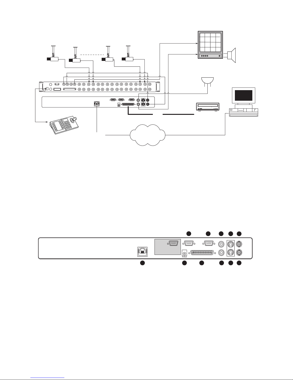
Figure 2A – Sample DVR1 System Installation
Figure 2A provides an illustration of a typical DVR1 system installation. Consider the peripheral devices necessary for
your system application, and perform the system connections according to the following installation instructions.
2.1 Mounting
The DVR1 is supplied as a desktop unit. If desired, your unit may be rack mounted using the rack mount kit
(included with the unit). Ensure that the mounting/installation location provides adequate ventilation and protection
from moisture. Do not obstruct the ventilation holes at the sides of the unit.
2.2 Connecting the DVR1
Rear Panel Connections
1. Refer to Figure 2B for details on the input/output connections supplied by the DVR1.
Figure 2B – DVR1 Rear Panel Connections
BOSCH
BOSCH
BOSCHBOSCH
Audio
BOSCH
(Optional)
Microphone
(Optional)
CONSOLE
VCR
SVHS IN
KEYBD
SVHS OUT
Multiplexer
VCR
MON A
MON B
1 2
IN
OUT
ALARM
SDA
3 4 5 6 7 8
ET
ETHERN
100
10/
1 ALARM IN
2 ALARM OUT
3 RECORD START IN
4 ALARM RECORD RESET
5 VEXT PULSE OUT
6 ERROR OUT
7 GROUND
8 VIDEOLOSS OUT
9 DISK END OUT
9 10
ACCESSORI
15
69
12V
13 14
11 12
ES
DC
SC
SI
15 16
232
RS-
S-video
IN
IN
VIDEO
IN
AUDIO
OUT
VIDEO
OUT
AUDIO
S-video
OUT
DVR1
CD-writer
Keyboard
Ethernet
SCSI
Network
15
1 ALARM IN
ETHERNET
10/100
2 ALARM OUT
3 RECORD START IN
4 ALARM RECORD RESET
5 VEXT PULSE OUT
6 ERROR OUT
7 GROUND
8 VIDEOLOSS OUT
9 DISK END OUT
69
1 2
3
ACCESSORIES
12V DC
5 6
RS-232
SCSI
4
1. Ethernet Port: For viewing Live or Recorded Images on a PC via the Ethernet (network).
2. Power Connector: Connect 12 Volt DC external power supply (provided).
NOTE: Ensure that the site's AC Power is stable and within the rated voltage of the external power supply. If the site's
AC power is likely to have spikes or power dips, use power line conditioning or an Uninterruptible Power Supply (UPS).
3. Accessory I/O Port: Used to connect peripheral devices such as alarm devices, alarm relays, or the VEXT (Video External Pulse)
connection (see additional pertinent information, including pinout details, in this section).
4. SCSI Port: For connecting a SCSI compatible archive device.
5. RS-232 Serial Port: Serial port for Flash Upgrading of software. Also used for external control of unit.
NOTE: The RS-232 port does NOT work with a modem. Use a Null Modem type cable (Bosch S1385 cable) to connect to this port.
6. Audio In (specified version only): Unbalanced, RCA style jack.
7. Audio Out (specified version only): Unbalanced, RCA style jack.
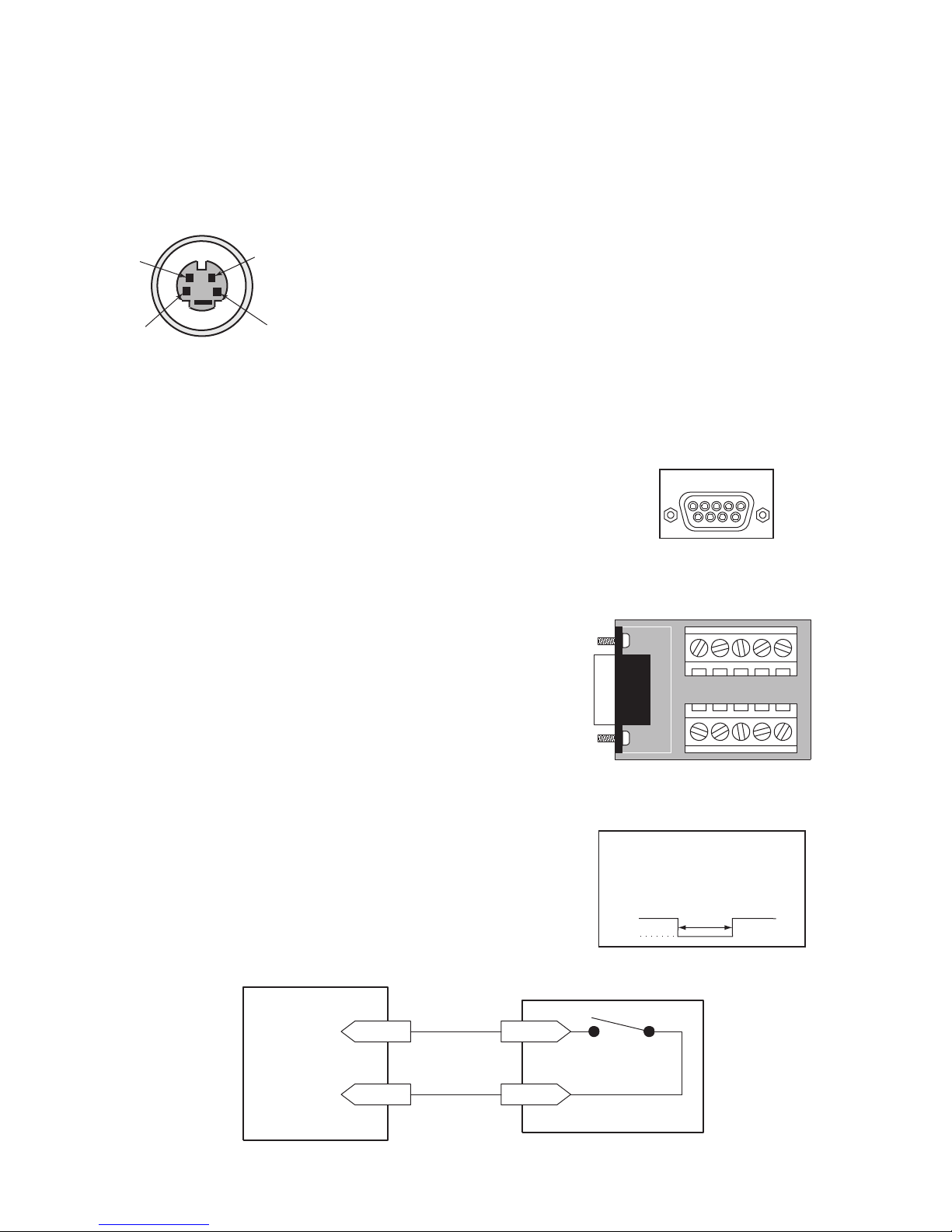
8. S-video In: Y/C video input with 4-pin mini-DIN style connector.
9. S-video Out: Y/C video output with 4-pin mini-DIN style connector.
10. Video In: Composite video input with BNC style connector.
11 . Video Out: Composite video output with BNC style connector.
AUDIO IN
AUDIO OUT
8
S-video IN
VIDEO IN
VIDEO OUT
S-video OUT
91011
7
11
2. Connect all peripherals (e.g. cameras, monitors, etc.) to the corresponding inputs/outputs on the DVR1 rear
panel.
CAUTION: DO NOT connect both S-video and Composite inputs at the same time. A hardware conflict will
occur, which could damage the unit.
3. When all connections have been completed, apply power to the system.
S-Video
• Cable must be purchased separately.
Ethernet Port
Ethernet port uses standard pinout configuration.
• For a DVR1 that connects directly to a Hub, use a straight-through connection.
• For a DVR1 that connects directly to a PC, use a crossover connection.
Accessories Port Connections
The rear panel of the DVR1 is equipped with an Accessories Port (DB-9 style
connector). Connect the Accessories PCB (supplied with the unit) to the
Accessories Port, then wire all accessories to the Accessories PCB.
If the Accessories PCB is lost or missing, contact Bosch Customer Service for a
replacement (Part Number 0900-0127a).
As an alternative to using the PCB connector, you may purchase a female
DB-9 connector and perform wiring and connections as detailed in the
following pin-out.
Pin 1: Alarm In Pin 6: Error Out
Pin 2: Alarm Out Pin 7: Ground
Pin 3: Record Start In Pin 8: Videoloss Out
Pin 4: Alarm Record Reset Pin 9: Disk End Out
(future feature)
Pin 5: VEXT Pulse Out Pin 10: Ground
NOTE: Refer to the multiplexer and other peripheral device manuals for
pertinent connection and synchronization information.
Functional descriptions of the connections provided by the DVR1 Accessories Port follow:
Alarm In: An alarm condition can be activated by an Active Low TTL
input, or by relay contact devices such as pressure pads, passive infrareds,
door switches, or similar devices
Normally Open Relay Alarm Connection
DB-9 Connector on
Rear Panel
Accessories PCB
4
2
3
1
Pin Signal
1. GND (Y)
2. GND (C)
3. Y-signal IN or OUT
4. C-signal IN or OUT
Input: Active Low TTL with pull-ups
or Normally Open Relay.
High: 5 V (12 V tolerant)
Low: Ground
ACCESSORIES
15
69
6
7
8
1
9
2
3
4
Minimum Duration: 0.5 Seconds
GND
5
Alarm Input
Ground
Accessories PCB
Pin 1
Normally Open
(Closes During Alarm)
Pin 7 or 10
Typical Alarm Device
Refer to each alarm device's
manual for specific wiring details.

12
Alarm Out: The Alarm Output is activated when a teletext alarm is read, or while the
Alarm Input is active. The Alarm output is only active for the duration of the alarm
event.
Record Start In: When activated, this connection places the unit in record mode.
Compatible with the Disk End Out signal from a second unit.
Alarm Record Reset: This feature is for future development and has not yet been
implemented.
VEXT Pulse Out: The Video External Pulse Connection (VEXT) simplifies
multiplexer operation by automatically synchronizing the multiplexer with the DVR1.
The DVR1 sends a VEXT pulse to the multiplexer, indicating that it is ready to
record the next image. The multiplexer responds by sending the next image to the
Video Input on the DVR1.
The VEXT connection is especially beneficial for units configured with dual record
speeds (Normal and Alarm).
NOTE: Use of the VEXT connection is highly recommended when connecting
the unit to a multiplexer.
Error Out: The Error Out signal is activated when the unit experiences any
operational or internal error.
Videoloss Out: The Videoloss Out signal is activated when the unit experiences
loss of video on the selected video input (Composite or S-video).
In the event of loss of video, VIDEOLOSS will be indicated near the upper
left-hand corner of the primary monitor.
Disk End Out: The Disk End Out is activated when there are 5 minutes of
recording space left on the hard disk.
Input: Active Low
High: 12 V
Low: Ground
Current Out: 50 mA Max
Short Circuit Protected.
Low for duration of alarm
Input: Active Low TTL with pull-ups
or Normally Open Relay.
High: 5 V (12 V tolerant)
Low: Ground
Minimum Duration: 0.5 Seconds
Output: Active Low
High: 5 V
Low: Ground (0.8 V Max)
Current Out: 50 mA Max
Short Circuit Protected.
Output: Open Collector
High: Transistor Off
Low: Transistor On
Active When On.
Current Out: 10 mA Max
Minimum Duration: 0.5 Seconds
 Loading...