

Bosch DVR1C1161 Installation Instructions Manual
DVR1C1161
Installatiehandleiding
Digital Recorder
NL
Istruzioni sull’installazione
Registratore digitaleIT
Instrukcja instalacji
Cyfrowy magnetowid
PL
Instruções de Instalação
Gravador Digital
PT
Installation Instructions
Digital Recorder
EN
Manuel d’installation
Enregistreur numériqueFR
Installationshandbuch
Digital Recorder
DE
Manual de instalación
Grabador digital
ES

ENGLISH......................................................................................................................................................................................... 3
FRANÇAIS .................................................................................................................................................................................. 25
DEUTSCH.................................................................................................................................................................................... 53
ESPAGÑOL ................................................................................................................................................................................ 77
NEDERLANDS ....................................................................................................................................................................... 103
ITALIANO.................................................................................................................................................................................. 127
PORTUGUÊS ......................................................................................................................................................................... 153
POLISH .......................................................................................................................................................................................177

Bosch Security Systems | 2004-6
DVR1C1161 | Installation Manual | Table of Contents EN | 3
1. SAFETY PRECAUTIONS .........................................................................................................................................................5
1.1 IMPORTANT SAFEGUARDS .......................................................................................................................5
1.2 FCC INFORMATION ......................................................................................................................................6
2. INTRODUCTION .........................................................................................................................................................................6
2.1 FEATURES ........................................................................................................................................................6
2.2 FRONT PANEL ................................................................................................................................................7
2.3 REAR PANEL ...................................................................................................................................................8
2.3.1 Power .....................................................................................................................................................8
2.3.2 RS232 serial connector ....................................................................................................................8
2.3.3 IR remote control eye connector .....................................................................................................8
2.3.4 LAN connector ....................................................................................................................................8
2.3.5 Alarm connections ..............................................................................................................................8
2.4 INTERCONNECTIONS ..................................................................................................................................9
2.4.1 Multiplexers ...........................................................................................................................................9
2.4.2 Quads ................................................................................................................................................. 10
2.4.3 Single camera ................................................................................................................................... 11
2.5 REMOTE CONTROL UNIT ........................................................................................................................ 12
2.6 NETWORKS .................................................................................................................................................. 12
3. OPERATION ...............................................................................................................................................................................13
3.1 QUICK INSTALL ........................................................................................................................................... 13
3.2 INSTANT RECORDING .............................................................................................................................. 13
3.3 ALARM RECORDING ................................................................................................................................. 13
3.3.1 Pre-alarm recording ......................................................................................................................... 13
3.4 NORMAL PLAYBACK ................................................................................................................................. 13
3.5 SEARCH PLAYBACK ................................................................................................................................. 14
3.6 COPY .............................................................................................................................................................. 14
3.6.1 Still image copy ................................................................................................................................ 14
3.6.2 Copy to movie file ............................................................................................................................ 14
3.7 SECURITY LOCK SETTING ..................................................................................................................... 14
4. MENU SET-UP ..........................................................................................................................................................................15
4.1 MAIN MENU ................................................................................................................................................... 15
4.2 CLOCK/LANGUAGE MENU ..................................................................................................................... 15
4.3 NORMAL RECORD MENU ....................................................................................................................... 15
4.4 ALARM RECORD MENU ........................................................................................................................... 15
4.5 TIMER MENU ................................................................................................................................................. 16

Bosch Security Systems | 2004-6
DVR1C1161 | Installation Manual | Table of Contents EN | 4
4.6 BUZZER MENU ............................................................................................................................................ 16
4.7 ARCHIVE MENU ........................................................................................................................................... 17
4.8 NETWORK MENU ....................................................................................................................................... 17
4.9 SYSTEM SETTING MENU ......................................................................................................................... 18
4.10 PASSWORD MENU .................................................................................................................................... 18
5. VIEW VIA INTERNET/INTRANET ..................................................................................................................................... 19
5.1 LOGIN ............................................................................................................................................................. 19
5.2 MAIN SCREEN ............................................................................................................................................. 19
5.2.1 Status message color ..................................................................................................................... 20
5.2.2 Live mode icons ............................................................................................................................... 20
5.2.3 Playback mode icons ...................................................................................................................... 20
5.2.4 Search ................................................................................................................................................ 20
6. SPECIFICATIONS ...................................................................................................................................................................21
6.1 RS-232 INTERFACE ................................................................................................................................... 21
6.1.1 RS-232 control protocol ................................................................................................................ 21
6.2 RECORDING TIME ...................................................................................................................................... 22
6.3 TECHNICAL SPECIFICATIONS .............................................................................................................. 23
Display abbreviations
II Pause
A.REC Alarm record
BASIC Basic quality
HIGH High quality
LOW Low quality
LOWER Lowest quality
MENU Menu
PAUSE Pause
P.E ND Pause end
PLAY Play
P.END Play end
P.R PT Play repea t
REC Record
SRCH Search
STDRD Standard quality
SUPER Superior quality
SYSLD System loading
T.REC Timer recording
*REC Lock record
P.B EG P lay begin
R.REC Remote record
Bosch Security Systems | 2004-6
DVR1C1161 | Installation Manual | Chapter 1 EN | 5
1 SAFETY PRECAUTIONS
1.1 IMPORTANT SAFEGUARDS
1. Please read these safety instructions carefully.
2. Please keep this User's Manual for later reference.
3. Please disconnect this equipment from connecter
before cleaning. Don't use liquid or sprayed
detergent for cleaning. Use moisture sheet or cloth
for cleaning.
4. Make sure the voltage of the power source when
connect the equipment to the power outlet.
5. All cautions and warnings on the equipment should
be noted.
6. Never pour any liquid into opening, this could cause
fire or electrical shock.
7. Never open the equipment. For safety reason, the
equipment should only be opened by qualified
service personnel.
8. If one of the following situations arises, get the
equipment checked by a service personnel :
a. Liquid has penetrated into the equipment.
b. The equipment has been exposed to moisture.
c. The equipment has not work well or you can not
get it work according to user's manual.
d. The equipment has dropped and damaged.
e. If the equipment has obvious sign of breakage.
9. Do not leave this equipment in an environment
unconditioned, storage temperature above 50°C, it
may damage the equipment.
10.Operation Ambient 50°C
11. Power cords : Use the proper power cord with
correct attachment plug type. If the power source is
120 V AC, use a power cord that has UL and CSA
approvals. If the power source is a 240 V AC supply,
use the tandem (T blade) type attachment plug with
ground conductor power cord that meets the
respective European country's safety regulations,
such as VDE for Germany. Plug need approval with
VDE 0620, connector approval by VDE 0625,
minimum 10A, power cord H05VV-F or VW-1,0.75
mm2 x 3G should be used.
12.
13. The back of the recorder should only be removed by
qualified maintenance and service personnel.
14. Danger of explosion if battery is incorrectly
replaced. A lithium battery is located inside the
enclosure of this recorder. Replace only with the
same or equivalent type. Dispose of the replaced
battery in an environmentally friendly way.
15.Keep ventilation openings free to avoid the recorder
for overheating.
16.Do not place the recorder in the immediate vicinity
of a heating source.
17. Do not install this equipment in a confined space
such as a bookcase or similar unit.
Cleaning
You can clean the unit with a moist fluff-free cloth or
shammy leather cloth.
Bosch has a strong commitment towards the
environment. This unit has been designed to respect the
environment as much as possible.
Danger
The lightning flash with arrowhead symbol,
within an equilateral triangle, is intended to alert
the user to the presence of an uninsulated
“dangerous voltage” within the product's
enclosure that may be of sufficient magnitude to
constitute a risk of electric shock to persons.
Warning
The exclamation mark within an equilateral
triangle is intended to alert the user to the
presence of important operating and
maintenance (servicing) instructions in the
literature accompanying the appliance.
Caution
To reduce the risk of electric shock, do not
remove cover (or back). No user-serviceable
parts inside. Refer servicing to qualified service
personnel.
Warning
To reduce the risk of fire or electric shock, this
apparatus should not be exposed to rain or
moisture and objects filled with liquids,such as
vases, should not be placed on this apparatus.

Bosch Security Systems | 2004-6
DVR1C1161 | Installation Manual | Chapter 2 EN | 6
1.2 FCC INFORMATION
This equipment has been tested and found to comply
with the limits for a Class B digital device, pursuant to
part 15 of the FCC Rules. These limits are designed to
provide reasonable protection against harmful
interference in a residential installation. This equipment
generates, uses and can radiate radio frequency energy
and, if not installed and used in accordance with the
instructions, may cause harmful interference to radio
communications. However, there is no guarantee that
interference will not occur in a particular installation. If
this equipment does cause harmful interference to radio
or television reception, which can be determined by
turning the equipment off and on, the user is
encouraged to try to correct the interference by one or
more of the following measures:
• Reorient or relocate the receiving antenna.
• Increase the separation between the equipment and
receiver.
• Connect the equipment into an outlet on a circuit
different from that to which the receiver is
connected.
• Consult the dealer or an experienced radio/ TV
technician for help.
Note
Any change or modification not expressly approved by
Bosch of the equipment authorization could void the
user's authority to operate the equipment. For additional
information or to speak to a representative, please
contact the Bosch Security Systems location nearest you
or visit our web site at www.boschsecuritysystems.com
2Introduction
The DVR1C1161 Digital Video Recorder provides
advanced recording and playback technology for
CCTV systems. The DVR allows uninterrrupted
recording in either continuous or time-lapse modes for
as long as a week or more. There are no video tapes to
change or store, and frequent, costly VCR maintenance
is eliminated.
The DVR can record at speeds up to 50/60 images per
second with PAL/NTSC formats and replay events
instantly. The DVR incorporates all the benefits of
digital video recording, is simple to install, and operates
just like a VCR. The highly efficient compression
technology, as well as the superior clarity and detail of
recorder images, make the DVR ideally suited for
integration with a wide range of multiplexers.
2.1 Features
• Provides superior quality images
• Pre-Alarm image recording
• Time lapse and real time recording
• Refresh rate up to 50 images for PAL and 60 images
for NTSC
• Quick Search by date/time, alarm events, and
recording list
• Fast and slow playback of recorded video in various
speeds
• On-screen setup menu and system timer
• Password protection
• RS-232 communication port
• Built-in M-JPEG compression/decompression with
configurable quality
• Audio recording capability
• Programmed with various time-lapse speeds
• Data can be stored on Compact Flash Card
• Remote control
• Remote view recordings and live pictures with
Web-based browser
• Compatible with Bosch and various other types of
multiplexers.
Warning
This device is intended for use in public areas
only. Surreptitious recording of oral
communications is strictly prohibited by U.S.
Federal law.
Bosch Security Systems | 2004-6
DVR1C1161 | Installation Manual | Chapter 2 EN | 7
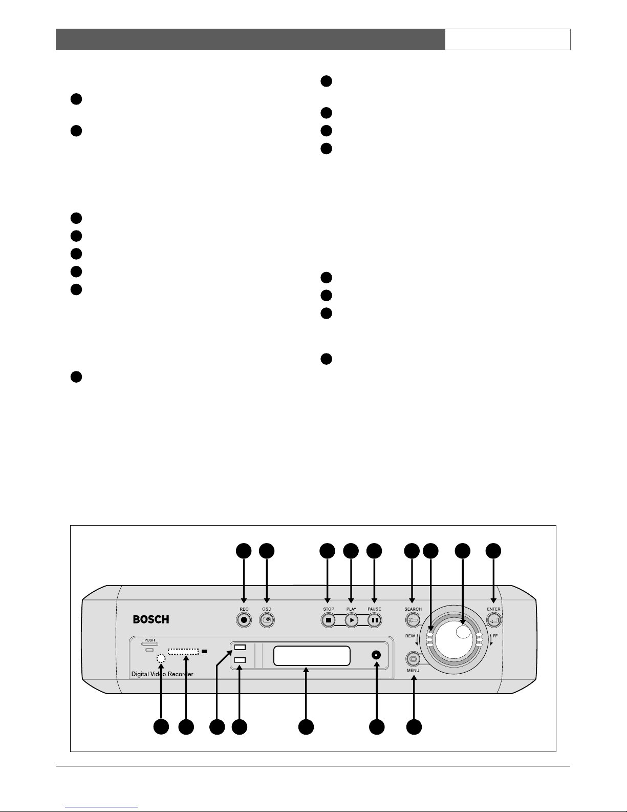
2.2 Front panel
REC: Press to start recording (red light in key lights
when unit is recording).
OSD: - Press once to display the time/date, disk
usage and playback rate.
- Press a second time to display size, record
position and play position.
- Press a third time to switch off the onscreen display.
STOP: Press to stop recording or playback.
PLAY: Press to start playback.
PAUSE: Press to pause the playback picture.
SEARCH: Press to enter the search menu.
Shuttle Ring:
In playback mode, turn Shuttle Ring clockwise to
speed up or counterclockwise to slow down the
forward or reverse play of the picture.
In pause mode, turn Shuttle Ring to move the
picture slowly forward or reverse.
Jog Dial:
In playback mode, turn Jog Dial to select the
playback speed.
In pause mode, turn Jog Dial to move forward or
backward image by image.
In menu mode, turn Jog Dial to navigate through
the menu pages or to select data values. Use
together with the ENTER key to set menu values.
ENTER: Press to confirm a selection or a changed
data value.
MENU: Press to enter or leave the setup menu.
Remote control IR receiver window.
LCD display
In standby mode, shows current date/time and the
quality and rate setting for normal recording.
In Recording mode, shows current date/time and
the REC and current recording rate.
In Playback mode, shows playback date/time and
the PLAY and current playback rate.
(For information on the displayed messages see the
abbreviations list at the beginning of this manual.)
ALARM: Indicator lights when an alarm occurs.
LAN: Indicator lights when network is accessed.
Compact Flash card slot: Insert a Compact Flash
Card. Press the black button beside the slot to
remove the card.
COPY: Press to copy still picture or video stream
onto Compact Flash card.
1 2 3 4 5 6 7 8 9
10121314 1115
16
1
2
3
4
5
6
7
8
9
10
11
12
13
14
15
16
Bosch Security Systems | 2004-6
DVR1C1161 | Installation Manual | Chapter 2 EN | 8
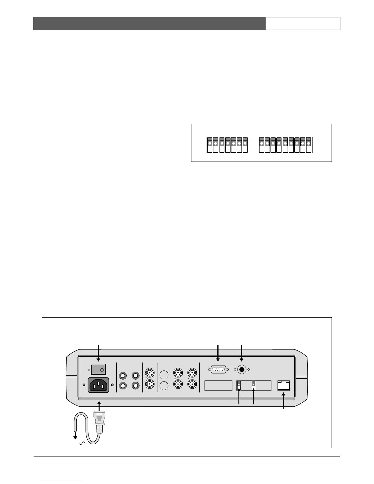
2.3 Rear panel
2.3.1 Power
Connect the power suppy cable to the power socket at
the rear of the unit. Use the power switch to switch the
unit ON or OFF.
2.3.2 RS232 serial connector
Connect D-Sub 9-pin connector to the RS232 port if
you want to control the unit remotely.
2.3.3 IR remote control eye connector
If the remote control IR receiver window at the front is
hidden from view (if the unit is mounted in a cupboard),
connect the optionally available extension IR cable to
the remote control connector. Position the receiver eye
so that it is in line-of-sight of the remote control unit.
2.3.4 LAN connector
To connect the unit to a network use the RJ-45 LAN
connector at the rear of the unit.
2.3.5 Alarm connections
The ALM-IN and ALM-RST inputs can be set to
Normally Open (N.O.) or Normally Closed (N.C.) in
the Alarm record menu.
GND: Ground connection.
ALM-IN: Apply a signal* here to start alarm
recording.
ALM-RST: Apply a signal* here to stop alarm
recording.
REC: A high level external recording request
signal* applied to this pin starts
recording. When the signal drops to low,
recording stops.
NC1, NC2: No connections.
* Signal
- switching voltage High: > 2 Vdc
- switching voltage Low: < 0.5 Vdc
- max. input voltage: 12 Vdc
The alarm output signals are:
GND: Ground connection.
ALM-NC**: When an alarm occurs, the connection
between this pin and ALM-COM is
open. Otherwise it is closed.
ALM-NO**: When an alarm occurs, the connection
between this pin and ALM-COM is
closed. Otherwise it is open.
ALM-COM**: Alarm common contact.
VEXT: Synchronization signal for multiplexer.
Output voltage: 5 Vdc
Output current: 100mA
DISKFULL: Disk full alarm output signal.
Output voltage: 5 Vdc
Output current: 100mA
NC3, NC4: No connections.
* * contact voltage max: 24 Vdc
max. switching current: 2A dc
Off
Power
AC 100-240
In1 In2
Out1 Out2 Monitor Out Out Out 1 Out 2
Looping out
RS 232 Remote Control
GND
ALM-NC
ALM-NO
ALM-CO
VEXT
DISKFULL
NC3
NC4
GND
In
In
Video
S-VideoMonitor In
Audio Mux main
LAN
GND
ALM-IN
ALM-RST
REC
NC1
NC2
GND
100-240 Vac
VEXTGND
Power switch
RS-232
connector
IR remote
control eye
connector
Network connector
Alarm connector
GND
ALM-NC
ALM-NO
ALM-CO
VEXT
DISKFULL
NC3
NC4
GND
GND
ALM-IN
ALM-RST
REC
NC1
NC2
GND
Alarm inputs
Alarm outputs
 Loading...