

Installation Instructions
for the DS778
ASIC-Based
Passive Infrared Intrusion Detector
1.0 Specifications
• Input Power: 6.0 VDC to 15.0 VDC; 18 mA @ 12.0 VDC
• Standby Power: There is no internal standby battery.
Connect to DC power sources capable of
supplying standby power if primary power
fails. For each hour of standby time
needed, 18 mAh are required.
Certificated Installations, A minimum of
4 hours (72 mAh) is required.
• Coverage: 200 ft. by 15 ft. (60 m by 4.5 m)
• Sensitivity: Adjustable for Intermediate or High.
• Alarm Relay: Form “C” reed relay with contacts rated at
28 VDC, 125 mA max. for DC resistive
loads.
• Tamper Switch: Normally Closed (with cover in place)
tamper switch. Contacts rated at 28 VDC,
125 mA max.
• Temperature: The storage and operating range is -40°F
to +120°F (-40°C to +49°C).
Certificated installations, the temperature
range is +32°F to +120°F (0°C to +49°C).
• Options: B328 Gimbal Mount Bracket, B335 Low
Profile Mount Bracket,B338 Ceiling Mount
Bracket, TC6000 Test Cord.
Note: Misalignment of the detector when using an optional
mounting bracket may reduce range.
2.0 Mounting
2.1 Mounting Considerations
• Select a location that is most likely to intercept an intruder moving
across the coverage pattern. The recommended mounting height
range is 6.5 ft. to 8.5 ft. (2 m to 2.6 m).
* The mounting surface should be solid and vibration free.
• Avoid direct hot and/or cold drafts, direct sunlight, heat sources,
windows, air conditioning outlets, and small animals.
• This detector won’t detect through glass.
• See
Section 8.0 Coverage Patterns
2.2 Surface or Corner Mounting
Note: For bracket mounting, refer to the installations supplied
with the bracket.
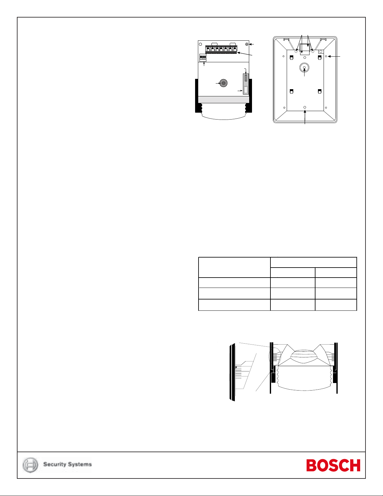
• Remove the cover. Insert a thin flathead screwdriver into the
notch at the bottom of the cover and pry up.
• Remove the chassis screw in the upper right corner of the
assembly (see
Figure A
). To remove the circuit board/mirror unit
from the enclosure, push the circuit board/mirror unit toward the
top of the enclosure until it clears its four retainer tabs, then lift
out.
.
For UL
For UL
• Open two holes (see
3
12
NO NCCTT
-+
OPEN
Configuration
Switches
LED
+2
0
Tamper Switch
-8
-16
Noise
Voltage
+2
0
-8
-16
Figure A
Chassis
Screw
T-Strip
) for surface or corner mounting.
Wiring Knockouts
Corner
Mounting
Holes (4)
Bracket
Mounting
Hole
Surface Mounting Holes
or Single Gang
Box Holes (2)
Figure A - Location of Major Items -
Circuit Board and Detector Enclosure
• Mark the location for the mounting screws. Use the enclosure
as a template. Pre-start the mounting screws.
• Open the appropriate wiring knockout and route the wiring
through (see
Section 3.0 Wiring
).
• Securely attach the detector.
• Replace the circuit board/mirror unit.
• Adjust the mirror.
Note: Excessive handling of the mirror surfaces may lead to
performance degradation.
- Adjust vertically from +2° to -18° by sliding the mirror forward
or back. See
Figures B
and C to set the correct Vertical Angle
based on the mounting height and desired range.
Vertical Angle Setting
Mounting Height [ft. (m)]
6.5 (2)
7.5 (2.3)
8.5 (2.6)
100 ft. (30 m)
-2°
-2°
-3°
200 ft. (60 m)
-1°
-2°
-2°
Figure B - Mounting Height/Range Chart
- The angle adjust markings are on the sides of the mirror
(see
Figure C
Set
at
-1°
).
-16
+2
0
-8
+2
0
-8
-16
+2
0
-8
-16
Mirror
Figure C - Setting Vertical Angle
- Slide the mirror forward or back until the angle hash marks
are in-line with the markers on each side of the frame.
- Horizontally ±10° by rocking the mirror side to side.
When the detector is installed so that its pattern is centered
down a narrow hallway, the coverage will probably not be
adequate since the detector will be “looking” mostly at the
walls leaving an open channel down most of the hallway as
illustrated here:
Narrow Hallway
Detector centered, Pattern centered
Depending on the dimensions of the hallway this can be
compensated for by mounting it in the center and adjusting
the horizontal angle as illustrated here:
Narrow Hallway
Detector centered, Pattern rotated 1° (1 click)
- Walk test the installation carefully to ensure adequate
coverage. See
Figure D
for horizontal angle adjustment
information.
10°
10°
5°
0°
3.1 Terminal Descriptions
• 1 (-) & 2 (+): Input Power (6 - 15 VDC). Use no smaller than
#22 AWG (0.8 mm) wire pair.
• 3 (NO), 4 (C), 5 (NC): Relay Contacts. Reed relay for silent
operation. Contacts rated at 3 watts, 125 mA, 28 VDC maximum
for DC resistive loads and protected by a 4.7 ohm resistor in the
common “C” leg of the rela y .
Do not use with capacitive or inductive
loads.
• 6 & 7: Normally Closed Tamper Contacts, rated 28 VDC,
125 mA.
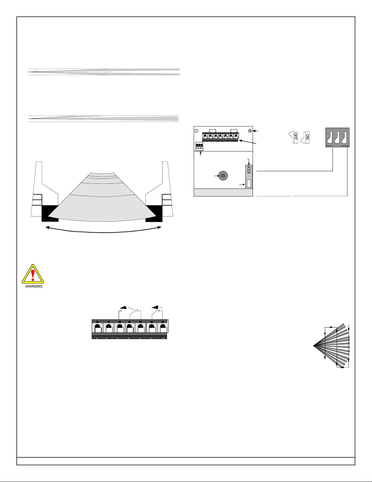
4.0 Configuration Switches
• Configure the detector using the appropriate switch settings
(see
Figure F
123
-+
PEN
O
Configuration
Switches
LED
Tamper Switch
).
NO NCCTT
Noise
Voltage
Chassis
Screw
T-Strip
1 ON
= LED ON
1 OFF
= LED OFF
2 ON and 3 OFF
2 OFF and 3 ON
2 ON and 3 ON
= High
= Intermediate
= Not Recommended
5°
0°
Figure F - Configuration Switch Locations
ON
OFF
12
OPEN
3
Left/Right Pattern Adjust (1 click = 1°)
Figure D - Horizontal Angle Adjustment
3.0 Wiring
Only apply power after all connections have been
made and inspected.
• Connect wiring as shown in
Contacts sh own in
normal co nditi on (no
alarm or tamper) with
power applied.
Figure E - Terminal Connections
• Seal the wire entrance with the foam plug provided.
Figure E
-+
.
Alarm Tamper
NO
NCCTT
4.1 LED Operation (S1)
• ON: Allows the LED to operate when activated by alarm.
• OFF: The LED will not operate on alarm.
4.2 Sensitivity Mode (S2 and S3)
• Intermediate Sensitivity: Recommended setting for any location
where an intruder is expected to cover only a portion of the
protected area. Tolerates normal environments on this setting.
• High Sensitivity: Fast response to intruder signals. For use in
quiet environments where thermal and illumination transients
are not anticipated.
5.0 Setup and Walk Testing
• Replace the cover on the unit. The cover should be in place
before testing the unit.
• Apply power to the detector.
• Wait for approximately two minutes, then start
walk testing.
• Walk test across the coverage pattern as
shown:
• The edge of the coverage is determined by
activation of the LED.
• Walk test the unit from both directions to determine the
boundaries.
• If the desired range cannot be achieved, try angling the mirror
up or down to assure the coverage pattern is not aimed too high
or low.
Page 2 © 2004 Bosch Security Systems DS778 Installation Instructions

6.0 Final T ests
Mirror Segment
to Pattern Refe rence
View of Front
Polished Surface
A
C
D
E
B
+2
0
-8
-16
+2
0
-8
-16
• Connect a DC VOM to the Noise Voltage pins (use TC6000).
• Replace the cover, routing the TC6000 cable through the notch
in the top of the case.
• Set meter scale for about 3.0 VDC.
- The base reference level for reading
background noise is approximately
2.0 VDC.
- Installations in quiet environments will
result in a steady reading between
1.9 VDC and 2.1 VDC.
TC6000
- Voltage changes greater than 0.75 VDC from the reference
level are desirable for good catch performance.
- If changes are less than +0.75 VDC, the device may fail to
respond if the temperature between the intruder and the
background is minimal.
• Turn on all heating and cooling sources that would normally be
in operation during times of protection.
• Stand away from the unit and outside the coverage pattern, then
monitor the background noise for at least 3 minutes.
- Readings should not deviate from the reference level by
more than ±0.15 VDC.
- For readings outside these limits; eliminate the cause,
re-point the unit slightly, or mask off the affected zones.
+
-
7.0 Maintenance
• At least once a year, the range and coverage should be checked
in accordance with the Walk Testing section.
• To ensure continual daily operation, the end user should be
instructed to daily walk through the outer edge of the coverage
pattern. This assures an alarm output prior to arming.
8.0 Coverage Patterns
• Masking Information
B
Before attempting any masking, be sure the chosen mirror
R
surface is the correct one (use the Mirror Segment to Pattern
W
Reference illustration to determine the relationship between
mirror sections and the pattern. When attempting to remove
masking, many adhesives will either destroy the mirror surface
or leave enough residue behind to reduce coverage
performance.
meters
0102030405060
6.5
0
7.5
7.5
Long Range Coverage
C
E
D
AB
Top View
2
20 40 600
0102030405060
meters
80 100 120 140 160 180 200feet
Side View
0
20 40 600
80 100 120 140 160 180 200feet
0
2.3
0
2.3
DS778 Installation Instructions © 2004 Bosch Security Systems Page 3

© 2004 Bosch Security Systems
130 Perinton Parkway, Fairpor t, New York, USA 14450-9199
Customer Service: (800) 289-0096; Technical Support: (888) 886-6189
03/04
DS778 Installation Instructions
P/N: 47884D Page 4
 Loading...