

Bosch DS7200V2-EXP Installation Manual

EN
DS7200V2-EXP
Installation Guide
DS7200V2-EXP
Control Panel
Addendum
DS7200 Installation Guide
TS50131-3 compliance
2011-09-16
Bosch Security Systems, Inc. | 04/12 | F01U253045-02
Max current draw
(Panel excluded)
Battery
capacity
Recharge time
(max)
System type
Prioritization of signals & indicators
Incoming signals are prioritized in chronological order. All signals are processed within 10 s.
Indicators displayed individually with text.
The control panel can meet all the options in Table 13, regarding notification outputs in the European standard for Intrusion
Systems.
Zone expanders
The zone expenders should be mounted inside the control panels enclosure for EN-approved systems.
Classification
DS7200 meets the Security Grade 2, Environmental Class 2
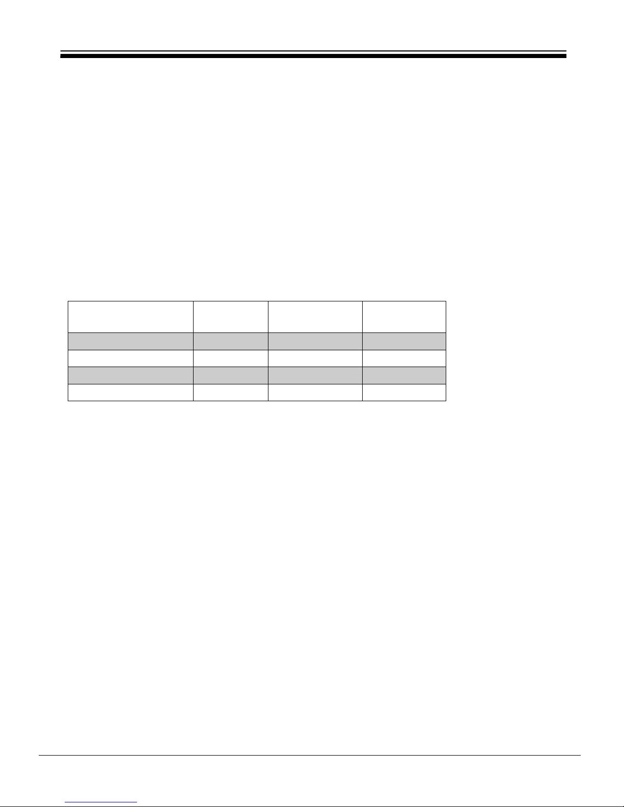
Current and battery capacity
400 ma 7,2 Ah 12 hours EN
800 mA 2 x 7,2 Ah 24 hours EN
1 A 18 Ah 48 hours EN
1,2 A 7-18 Ah - Non approved
Code combinations
The number of code combinations:
4-digit code allows for 10,000 combinations
5-digit code allows for 100,000 combinations
6-digit code allows for 1 million combinations
7-digit code allows 10 million combinations
The number of free combinations = code combinations – number of users
Weight and dimensions
Material: 1.0 mm thick cold-rolled steel
Dimensions (H x W x D): 36.8 x 31.8 x 7.6 cm
Weight 5.5 kg

DS7200V2-EXP | Installation Guide | Contents
Bosch Security Systems, Inc. | 04/12 | F01U253045-02
EN | 3
Contents
1. Introduction ............................................................................................................................ 7
1.1 Documentation Conventions ..............................................................................................................7
1.2 Scope of Document ............................................................................................................................7
1.3 Specifications .....................................................................................................................................8
1.4 Standard Features ..............................................................................................................................8
1.5 Control Panel Assembly ......................................................................................................................9
1.6 Listings and Approvals ........................................................................................................................9
1.7 System Options ..................................................................................................................................9
1.8 System Batteries .............................................................................................................................. 10
1.9 Available Power ................................................................................................................................ 10
1.10 Installer Keypad/RPS Connector ...................................................................................................... 10
2. System Installation and Setup ............................................................................................... 11
2.1 Control Panel Installation ................................................................................................................. 11
2.2 Arming Device Installation ................................................................................................................ 15
2.3 On-board Sensor Loop Setup ........................................................................................................... 18
2.4 On-board Output Setup .................................................................................................................... 21
2.5 RF3227E RF Receiver Setup ............................................................................................................. 22
2.6 Off-board Sensor Loop Setup (DX2010) .......................................................................................... 23
2.7 Off-board Output Setup (DX3010) ................................................................................................... 29
2.8 RS-232 Serial Interface Setup (DX4010i/DX4010) ............................................................................ 31
2.9 Network Interface Module (DX4020) ................................................................................................ 36
2.10 Door Access Control Module (DACM) .............................................................................................. 38
2.11 System Power Up ............................................................................................................................. 40
2.12 System Status LED ........................................................................................................................... 40
2.13 Installer Keypad ................................................................................................................................ 40
2.14 Installer Mode ................................................................................................................................... 41
2.15 Installer Menu ................................................................................................................................... 41
2.16 Keypad Programming ........................................................................................................................ 45
2.17 Keypad Test [#][9][1] ....................................................................................................................... 47
2.18 Always Force Arm ............................................................................................................................. 48
3. Control Panel Programming .................................................................................................. 49
3.1 Understanding the Option Parameter Charts ................................................................................... 49
3.2 Panel-Wide Parameters ..................................................................................................................... 50
3.3 Area-Wide Parameters ...................................................................................................................... 65
3.4 User Interface ................................................................................................................................... 68
3.5 Zone Parameters .............................................................................................................................. 80
3.6 Output Parameters ........................................................................................................................... 86
3.7 Sked Parameters .............................................................................................................................. 96
3.8 Data Bus Device Parameters............................................................................................................. 99
3.9 Network Communication ................................................................................................................ 101
3.10 DACM Configuration ....................................................................................................................... 105
3.11 Test the System .............................................................................................................................. 107
4. Reference Materials ............................................................................................................ 108
4.1 Control Panel Events and Reporting Formats ................................................................................. 108
4.2 Troubleshooting .............................................................................................................................. 120
4.3 Data Bus Address Quick Reference ................................................................................................ 122
4.4 Communication Attempt Tables ..................................................................................................... 123
4.5 Call for Service Details ................................................................................................................... 125
4.6 User Keypad Commands ................................................................................................................. 126
4.7 History Log ..................................................................................................................................... 127
4.8 Standby Battery Calculation ........................................................................................................... 128
4.9 Wiring Label .................................................................................................................................... 129
4.10 Glossary .......................................................................................................................................... 131

DS7200V2-EXP | Installation Guide | Figures
Bosch Security Systems, Inc. | 04/12 | F01U253045-02
EN | 4
Figures
Figure 1: Enclosure Installation .......................................................................................................... 11
Figure 2: Control Panel Board Mounting ............................................................................................ 12
Figure 3: Standby Battery Connections .............................................................................................. 12
Figure 4: RAM Backup Battery ............................................................................................................ 13
Figure 5: RJ31X/RJ38X Wiring ............................................................................................................ 13
Figure 6: Ground Start ........................................................................................................................ 14
Figure 7: Keypad Jumper Plug Configuration ..................................................................................... 15
Figure 8: Keypad to Control Panel Wiring ........................................................................................... 15
Figure 9: Keypad to Control Panel Wiring (External Power Supply) .................................................. 16
Figure 10: Keyswitch: Tamper Wired Zone Configuration .................................................................... 16
Figure 11: Maintained Keyswitch: Single EOL Resistor Configuration ................................................. 17
Figure 12: Momentary Keyswitch: Single EOL Resistor Configuration ................................................. 17
Figure 13: Keyswitch: Zone Doubled Configuration ............................................................................. 17
Figure 14: Keyswitch: No EOL Resistor Configuration ......................................................................... 17
Figure 15: Tamper-Wired Zone Configuration ...................................................................................... 18
Figure 16: Single Zone Sensor Loop Wiring ......................................................................................... 19
Figure 17: On-board Doubled Zone Sensor Loop Wiring ...................................................................... 19
Figure 18: Single Zone Sensor Loop Wiring (No EOL) ......................................................................... 20
Figure 19: 4-wire Smoke Detector (Tamper-wired) .............................................................................. 20
Figure 20: 4-wire Smoke Detector (Single EOL Resistor) ................................................................... 21
Figure 21: PO 1 Wiring (PO 1 Jumper Shorted) ................................................................................... 21
Figure 22: PO1 Dry Contact Wiring (No PO 1 Jumper) ........................................................................ 21
Figure 23: PO 1 Positive Alarm Trigger Wiring ...................................................................................... 22
Figure 24: PO 2 to PO 4 Wiring ............................................................................................................ 22
Figure 25: RF3227E Address Jumper Settings ..................................................................................... 22
Figure 26: RF3227E to Control Panel Wiring ........................................................................................ 23
Figure 27: Standard DX2010 Installation Locations ............................................................................. 23
Figure 28: Optional DX2010 Mounting Locations ................................................................................. 24
Figure 29: DX2010 to Control Panel Wiring .......................................................................................... 24
Figure 30: DX2010 to Control Panel Wiring (External Power Supply) .................................................. 25
Figure 31: DX2010 Auxiliary Output Wiring .......................................................................................... 25
Figure 32: DX2010 Tamper Input Wiring .............................................................................................. 26
Figure 33: DX2010 No Tamper .............................................................................................................. 26
Figure 34: DX2010 Tamper-Wired Zone Wiring..................................................................................... 26
Figure 35: DX2010 Single EOL Zone Wiring ......................................................................................... 27
Figure 36: DX2010 Doubled Zone Wiring ............................................................................................. 27
Figure 37: DX2010 DIP Switch Configuration ....................................................................................... 28
Figure 38: DX2010 Status LED Location .............................................................................................. 28
Figure 39: DX3010 to Control Panel Enclosure Installation ................................................................. 29
Figure 40: DX3010 to Control Panel Wiring .......................................................................................... 30
Figure 41: DX3010 Output States ......................................................................................................... 30
Figure 42: DX3010 to Control Panel Wiring (External Power Supply) .................................................. 30
Figure 43: DX3010 DIP Switch Configuration ....................................................................................... 31
Figure 44: DX4010i to Control Panel Wiring ......................................................................................... 32
Figure 45: DX4010i to Control Panel Wiring (External Power Supply) ................................................. 32
Figure 46: DX4010i RPS Direct Connect Address Setting .................................................................... 33
Figure 47: DX4010i Direct Connection ................................................................................................. 33
Figure 48: DX4010 Direct Connection .................................................................................................. 34
Figure 49: P1 Jumper Pin Settings ....................................................................................................... 34
Figure 50: DX4010 P2 Jumper Pin Settings.......................................................................................... 35
Figure 51: RS-232 Device DIP Switch Setting ...................................................................................... 35
Figure 52: DB9 Connector Layout ........................................................................................................ 35

DS7200V2-EXP | Installation Guide | Figures
Bosch Security Systems, Inc. | 04/12 | F01U253045-02
EN | 5
Figure 53: Network Communication DIP Switch Setting ...................................................................... 36
Figure 54: Standard DX4020 Mounting Locations ................................................................................ 36
Figure 55: Optional DX4020 Mounting Locations ................................................................................. 36
Figure 56: DX4020 to Control Panel Wiring .......................................................................................... 37
Figure 57: DX4020 to Control Panel Wiring (External Power Supply) .................................................. 37
Figure 58: DX4020 Ethernet/Serial Status LEDs .................................................................................. 38
Figure 59: DACM to Control Panel Wiring ............................................................................................ 39
Figure 60: DACM to Control Panel Wiring (External Power Supply) .................................................... 39
Figure 61: System Status LED .............................................................................................................. 40
Figure 62: Installer Keypad to Control Panel Wiring ............................................................................. 40
Figure 63: PK32 to Control Panel Connections .................................................................................... 44
Figure 64: Routing Destination Phone Number Configured for Basic Pager ........................................ 53
Figure 65: DS7200V2 Wiring Label ..................................................................................................... 129

DS7200V2-EXP | Installation Guide | Tables EN | 6
Bosch Security Systems, Inc. | 04/12 | F01U253045-02
Tables
Table 1: Document Overview .............................................................................................................. 7
Table 2: Control Panel Specifications ................................................................................................. 8
Table 3: Keypad Address Pin Settings ............................................................................................... 15
Table 4: Keypad to Control Panel Wire Length ................................................................................. 15
Table 5: DX2010 to Control Panel Wire Length ................................................................................. 24
Table 6: DX2010 to External Power Supply Wire Length .................................................................. 24
Table 7: Control Panel Locations for DX2010 Address 106 .............................................................. 27
Table 8: Control Panel Locations for DX2010 Address 107 (DS7240V2 only) .................................. 27
Table 9: DX2010 Address Settings .................................................................................................... 28
Table 10: DX2010 DIP Switch Settings ............................................................................................... 28
Table 11: DX3010 Wire Lengths .......................................................................................................... 30
Table 12: DX3010 Address DIP Switch Settings ................................................................................. 31
Table 13: DX4010i/DX4010 Wire Lengths ........................................................................................... 31
Table 14: DX4010i/DX4010 Diagnostic LED Functions ....................................................................... 35
Table 15: DB9 Pin Configuration ......................................................................................................... 35
Table 16: DX4020 Wire Lengths .......................................................................................................... 37
Table 17: Ethernet/Serial Status LED Functions ................................................................................. 38
Table 18: DACM Wire Lengths ............................................................................................................. 38
Table 19: System Status LED Operation ............................................................................................. 40
Table 20: Reserved and Expert Addresses .......................................................................................... 46
Table 21: Key/Character Assignments ................................................................................................. 47
Table 22: Phone Number Entry Selections .......................................................................................... 50
Table 23: Personal Dialing Format Configuration ................................................................................ 52
Table 24: Report Tone Selections ....................................................................................................... 52
Table 25: Format Field Options ........................................................................................................... 54
Table 26: Account Number Addresses/Defaults .................................................................................. 65
Table 27: Account Number Entry Selections ....................................................................................... 65
Table 28: User Configuration ............................................................................................................... 70
Table 29: DS7446KP Keypad Icon Functions ...................................................................................... 73
Table 30: Location Configuration Parameters ..................................................................................... 80
Table 31: Default Zone Function Type Selections ............................................................................... 83
Table 32: Location Text Addresses/Defaults ....................................................................................... 84
Table 33: Output Configuration Parameters ....................................................................................... 86
Table 34: Output Function Types ........................................................................................................ 88
Table 35: Output Mode Options .......................................................................................................... 93
Table 36: Pulse Mode Configuration ................................................................................................... 95
Table 37: One Shot Mode Configuration ............................................................................................. 95
Table 38: Sked Configuration Parameters ........................................................................................... 96
Table 39: IP Address Entry Selections .............................................................................................. 101
Table 40: Control Panel Events and Reporting Formats ................................................................... 109
Table 41: Data Bus Address Quick Reference ................................................................................... 122
Table 42: Destination 1 Only ............................................................................................................. 123
Table 43: Destination 2 Only ............................................................................................................. 123
Table 44: Destinations 1 and 2 .......................................................................................................... 124
Table 45: Call for Service Details ...................................................................................................... 125
Table 46: System Arming/Disarming Functions ................................................................................. 126
Table 47: Other System Functions .................................................................................................... 126
Table 48: History Log Display Descriptions ....................................................................................... 127
Table 49: History Log Communication Status Values ........................................................................ 127
Table 50: Standby Battery Calculation .............................................................................................. 128
Table 51: Terminal Descriptions ........................................................................................................ 130
DS7200V2-EXP | Installation Guide | 1. Introduction
Bosch Security Systems, Inc. | 04/12 | F01U253045-02
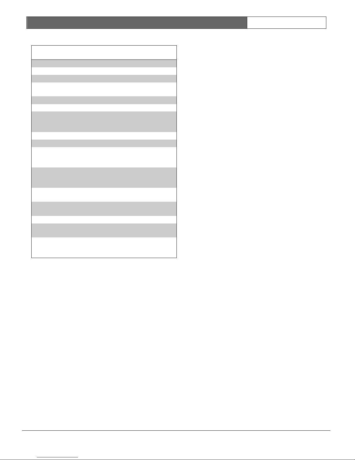
Table 1: Document Overview
Document
Part
Number
Description
included.
1.1.3 Other Conventions
1. Introduction
1.1 Documentation Conventions
1.1.1 Type Styles Used
To help identify important items in the text, the
following type styles are used:
Bold text Indicates important text or terms
that you should note.
Italicized text Refers you to a drawing, table, or
other section of this document.
[#][9][1] Bracketed numbers represent
keypad keys. When next to one
another, they represent the key
sequence to press for a particular
function. For this example, pressing
[#] followed by [9] and [1] begins
the keypad test function.
1|6
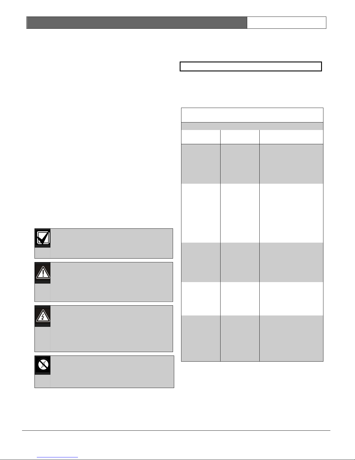
1.1.2 Notes, Cautions, and Warnings
Throughout this document there are important
Numbers separated by a vertical bar
represent output function types.
This example is for Output Function
Type 1|6:
Strobe.
Programming parameter titles are identified as
follows:
Programming Parameter Title
1.2 Scope of Document
See below for an overview of this document and
other documents related to the
DS7240V2/DS7220V2 Control Panels:
User’s Guide 4998153894 Contains keypad
Installer’s
Guide (this
document)
notes that address personal and/or equipment
safety issues, system operation issues, etc. They
are set off as follows:
The Important Note identifies
information intended for successful
operation.
Expert
Programmin
g Guide
The Caution Note identifies
information intended to prevent an
incident that could prohibit the
functionality of the
program/equipment.
Release
Notes
The Warning Note identifies
information intended to prevent an
incident that could prohibit the
System
Worksheet
functionality of the
program/equipment and/or personal
injury.
The No Static Note identifies
components that are static-sensitive.
Follow anti-static procedures when
handling these components.
EN | 7
operation instructions
for the end-user.
Covers use of the LCD
(text) keypad and the
LED keypad.
4998153893 Contains all wiring and
setup instructions,
and basic
programming
parameters with
descriptions.
Troubleshooting
information also
4998153891 Contains all
programming
parameters with
descriptions and
keypad programming
instructions.
4998153890 Contains issues with
control panel that
were found after
printing of the
documentation.
4998153887 Contains all
programming
parameter defaults
and space to record
any default changes
made during setup of
the control panel.
DS7200V2-EXP | Installation Guide | 1. Introduction
Bosch Security Systems, Inc. | 04/12 | F01U253045-02
Table 2: Control Panel Specifications
Environmental Specifications
Voltage Input to Control Panel
Power Outputs
Keypads
1.3 Specifications
1.4.3 Areas and Accounts
The DS7240V2 supports up to 4 independent
areas. The DS7220V2 supports up to 2
Temperature +32°F to +122°F (0°C to +50°C)
Relative Humidity 5 to 85% at 86°F (30°C) non-
condensing
independent areas.
All zones can be assigned to a single area, or
spread out over the available areas.
Users arm and disarm the control panel by area,
and can arm and disarm several areas with one
function. The installer can assign an authority
Primary 18 VAC, 50 VA
Secondary Sealed lead acid rechargeable
battery
(12 VDC, 7 Ah or 18 Ah).
level to a PIN that allows a user to arm an area
from a remote keypad in another area.
Assigning each area its own account number
creates separate accounts in one control panel.
Assigning the same account number to different
areas groups them together into one account.
Continuous Power Up to 1.2 A at 12 VDC nominal
(continuous supply) total for all
devices and outputs.
Alarm Power 1.85 A for fire and combined
fire/burglary. Applies to all four
outputs combined.
Minimum
Operating Voltage
Data Bus 12 VDC nominal. 305 m of 0.8 mm
10.2 VDC
(#22 AWG) cable
Area options include exit tone and delay,
separate fire and burglary outputs and auto
opening and closing Skeds (see Sked Parameters
on page 96 for more information).
Area 1 can be programmed as a “common” area.
See Arming Options 2 on page 63.
A “First to Open, Last to Close” arming option is
available (see Arming Options 2 on page 63).
1.4.4 Programmable Outputs
Four on-board programmable outputs (PO 1 to
Maximum Number
per System
Compatible
Keypads
1.4 Standard Features
1.4.1 Communicator
The control panel uses a built-in digital
communicator to send reports to the receiver. It
can send reports in Contact ID, SIA 300, SIA 300
with Text, Personal Dialing Format, and Basic
Pager Format.
1.4.2 Zones
The DS7240V2 supports up to 40 zones using on-
board and off-board (including input expanders
and wireless devices). The DS7240V2 supports
up to 5 DX2010 Input Expanders.
The DS7220V2 supports up to 24 zones using onboard and off-board (including input expanders
and wireless devices). The DS7220V2 supports
8
DS7445i or DS7445V2 LED
Keypad; DS7447E or DS7447V2
Text Keypad; DS7446KP Keypad
PO 4) are available on both control panels.
The DS7240V2 supports up to 20 programmable
outputs (4 on-board, 16 off-board using two
DX3010 Output Expanders).
The DS7220V2 supports up to 12 programmable
outputs (4 on-board, 8 off-board using one
DX3010 Output Expander).
See On-board Output Setup on page 21 and Offboard Output Setup (DX3010) on page 29.
1.4.5 Users
The control panel allows up to 32 individual
users. Each user is assigned a Personal
Identification Number (PIN) and an authority
level. Authority levels determine which functions
users can perform.
1.4.6 Keyswitch
Users can arm and/or disarm any available area
with maintained or momentary closure devices
such as keyswitches. Zone programming
determines the keyswitch’s operation.
up to 3 DX2010 Input Expanders.
On-board sensor loops are marked L-1 to L-8 on
both control panel types.
EN | 8

DS7200V2-EXP | Installation Guide | 1. Introduction
Bosch Security Systems, Inc. | 04/12 | F01U253045-02
C
1.4.7 Alarm Event Memory
The system uses alarm event memory to store
alarm events for each area. You can view the area
alarm events at a keypad assigned to the area.
The control panel clears the area’s alarm event
memory and starts storing new alarm events
when you arm the area. Alarm events are
permanently stored in the control panel’s history
log.
1.4.8 History Log
The system stores 254 events from all areas in its
event log.
Events can be stored even if the control panel
does not send a report for them. You can view
the log at a text keypad, print it locally using the
DX4010i/DX4010 RS-232 Serial Interface Module
and a serial printer, or upload it to the Remote
Programming Software (RPS).
1.4.9 Wireless (RF) Devices
The control panel supports a variety of wireless
sensor devices, which can be included in the 40zone maximum.
1.5 Control Panel Assembly
You should receive the following parts:
Documentation Pack
• DS7200V2 Installation Guide (this document)
(P/N: 4998153893)
• DS7200V2 Expert Programming Guide
(P/N: 4998153891)
• System Worksheet (P/N: 4998153887)
• Release Notes (P/N: 4998153890)
• User’s Guide (P/N: 4998153894)
Assembly
• Control Panel Assembly
• Red Battery Lead (P/N: 47720B)
• Black Battery Lead (P/N: 47721B)
• 2.2 k EOL Resistors (16 total)
• 3.65 k EOL Resistors (8 total)
• Tamper Switches
1.6 Listings and Approvals
•
• This product fulfills the requirements of
EN 50131-1, 50131-2, CLC/TS 50131-3
1.7 System Options
1.7.1 Arming Devices
• DS7445i LED Keypad: LED keypad that
displays up to 16 zones.
• DS7445V2 LED Keypad: LED keypad in new
faceplate design.
• DS7447E LCD (Text) Keypad: Text keypad
that displays system information and
programmable text.
• DS7447V2 LCD (Text) Keypad: Text keypad
in new faceplate design.
• Door Access Control Module (DACM): The
DACM grants or restricts access to a door
using a keypad/credential reader, a Request
to Exit (REX) input, and/or a door contact.
Each DACM supervises one door.
1.7.2 Data Bus Devices
• DX2010 Input Expander: Provides 8
additional input loops. The DS7240V2
supports up to 5 modules; the DS7220V2
supports up to 3 modules. Also available:
DX2014 (DX2010 with AE20 ABS plastic
enclosure).
• DX3010 Octo-Output Expander: Provides 8
independent, programmable Form “C” relay
outputs. The DS7240V2 supports up to 2
modules; the DS7220V2 supports 1 module.
• DX3020 Module: The DX3020 is an X-10
Interface Module. It can emulate up to 2
DX3010 Octo-Output Expanders. One allowed
per system.
• DX4010i RS-232 Serial Interface Module:
DTE RS-232 serial interface module that
provides a connection point to the system for
serial devices such as a printer. Can also be
used to create a remote programming direct
connection with RPS. It does not occupy a
control panel address when used this way.
One allowed per system
• DX4010 RS-232 Serial Interface Module:
Provides a connection point to the system for
serial devices such as a printer. Can also be
used to create a remote programming direct
connection with RPS. It does not occupy a
panel address when used this way. One
allowed per system.
• DX4020 Network Interface Module:
Provides bi-directional communication over
an Ethernet network. Can also be used for
remote programming sessions with RPS. One
allowed per system. Firmware revision 2.10
or greater is required to use the DX4020.
EN | 9

DS7200V2-EXP | Installation Guide | 1. Introduction
Bosch Security Systems, Inc. | 04/12 | F01U253045-02
1.7.3 RF Devices
• RF3227E RF Receiver: Supervises the use of
wireless devices. Up to 2 allowed per system.
• RF3332E RF Keyfob: 2-button keyfob that
can arm/disarm the system and create a
Panic event if programmed.
• RF3334E RF Keyfob: 4-button keyfob that
can arm/disarm the system and create a
Panic event if programmed. It can also
control other devices.
• RF3401E Point Transmitter: Point
transmitter that features a supervised sensor
loop and a magnetic reed switch. External
magnet assembly allows for quick and easy
installation on doors and windows.
• RF3405E Inertia Transmitter: Magnetic and
dry contact wireless transmitter with a builtin inertia sensor used for monitoring doors,
windows, or other dry contact devices.
• RF3503E Two-Button Transmitter:
Wireless, two-button transmitter that sends a
medical or panic alarm signal to the
monitoring system.
• RF1100E Glassbreak Detector: Wireless
transmitter used for detecting breaking glass.
• RF280ETHS Wireless Smoke Detector:
Wireless photoelectric smoke detector with
built-in 135°F (57°C) heat sensor and 85 dB
sounder.
• RF835E Wireless TriTech PIR/Microwave
Detector: Wireless detector that utilizes
passive infrared (PIR) technology, microwave
(MW) technology, and artificial intelligence to
detect motion.
• RF940E Wireless PIR Detector: High
performance PIR motion sensor.
1.7.4 Programming Tools
• DS7447E/DS7447V2 Text Keypad: Required
for keypad programming.
• PK32 Program Key: Copy system
programming entries to key for quick delivery
to another system. Can also be used as a
backup disk.
• Remote Programming Software (RPS):
Remote programming and diagnostic tool.
1.8 System Batteries
1.8.1 Standby Battery
12 V, 7 Ah or 18 Ah sealed lead-acid rechargeable
battery
• Power Sonic: PS-1270; PS-12180
• YUASA: NP7-12; NPG18-12
1.8.2 RAM Backup Battery
• 3 V coin-type lithium battery (Panasonic
CR2032 or equivalent)
1.9 Available Power
1.9.1 Auxiliary Power
Use auxiliary power terminals to power devices
requiring continuous power. Up to 1.2 A is
available for continuously powered devices.
1.9.2 Alarm Power
The Alarm Power (ALRM +) terminal provides
positive 12 VDC for Programmable Output 2 (PO
2) when it is configured as a siren driver and PO
1 when it is configured as the alarm output. Up to
1.85 A of alarm power is available.
1.10 Installer Keypad/RPS Connector
Use the Aux/Data connector to connect an
Installer Keypad or a DX4010i/DX4010 to the
control panel for programming and diagnostics.
EN | 10
DS7200V2-EXP | Installation Guide | 2. System Installation
and Setup
EN | 11
Bosch Security Systems, Inc. | 04/12 | F01U253045-02
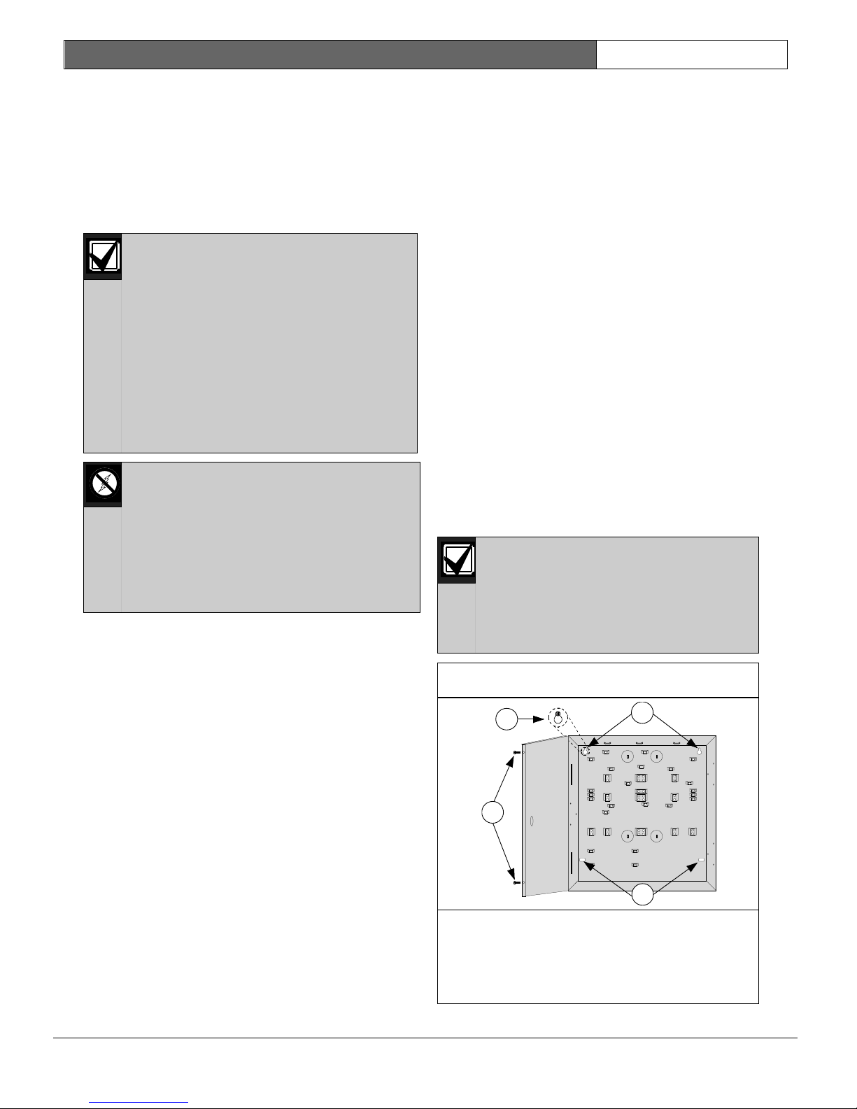
Figure 1: Enclosure Installation
1
3
2
4
If you think that EMI could be a problem, use
2. System Installation and
shielded cable. The drain wire for the shielded
cable must have continuity from the earth ground
Setup
2.1 Control Panel Installation
The control panel and enclosure are shipped
together. Hardware to attach the enclosure to the
wall is not supplied.
terminal on the control panel to the end of the
wire run. If continuity is not maintained, the
shielded cable can aggravate potential noise
problems rather than eliminate them.
Connecting the drain wire to ground at any place
other than the control panel’s earth ground
Only qualified, authorized service
personnel should install and maintain
this system. Test the entire system at
least once a week, and have a
qualified technician check the system
at a minimum of once every three
years.
As this is permanently connected
equipment, a readily accessible
disconnect device shall be
incorporated into the building
installation wiring.
The control panel contains staticsensitive components and must be
handled with care. Follow anti-static
procedures when handling it.
Touch the control panel’s earth
ground terminal to discharge any
static charge you may be carrying
before working on it.
2.1.1 Electro Magnetic Interference (EMI)
EMI might occur if you install the system or run
system wires near any of the following:
terminal might also create problems. If you cut
the drain wire to install devices, be certain to
splice it together. Carefully solder and tape all
splices.
2.1.2 Enclosure Installation
Knock out the desired wire entrances on the
enclosure.
Use the enclosure as a template and mark the top
mounting holes on the mounting surface.
Pre-start the screws (not supplied) for these
holes.
Place the enclosure onto these screws. See
Figure 1.
Tighten the screws.
Screw in the remaining two screws into the
bottom holes. See Figure 1.
Use proper anchor and screw sets
when installing the enclosure on
non-load-bearing surfaces, such as
dry wall.
Use the screws provided to secure
the enclosure cover (see Figure 1).
• Computer network system
• Electrical lines, fluorescent fixtures, or
telephone lines
• Amateur radio transmitter site
• Heavy machinery and motors
• High voltage electrical equipment or
transformers
• PBX telephone system
• Public service (police, fire, etc.) using radio
communications
• Radio station transmitter site or other
broadcast station equipment
• Welding shop
1- Screws for securing the cover
2- Slide enclosure screws into upper portion of
mounting hole
3- Top holes
4- Bottom holes
DS7200V2-EXP | Installation Guide | 2. System Installation
and Setup
Bosch Security Systems, Inc. | 04/12 | F01U253045-02
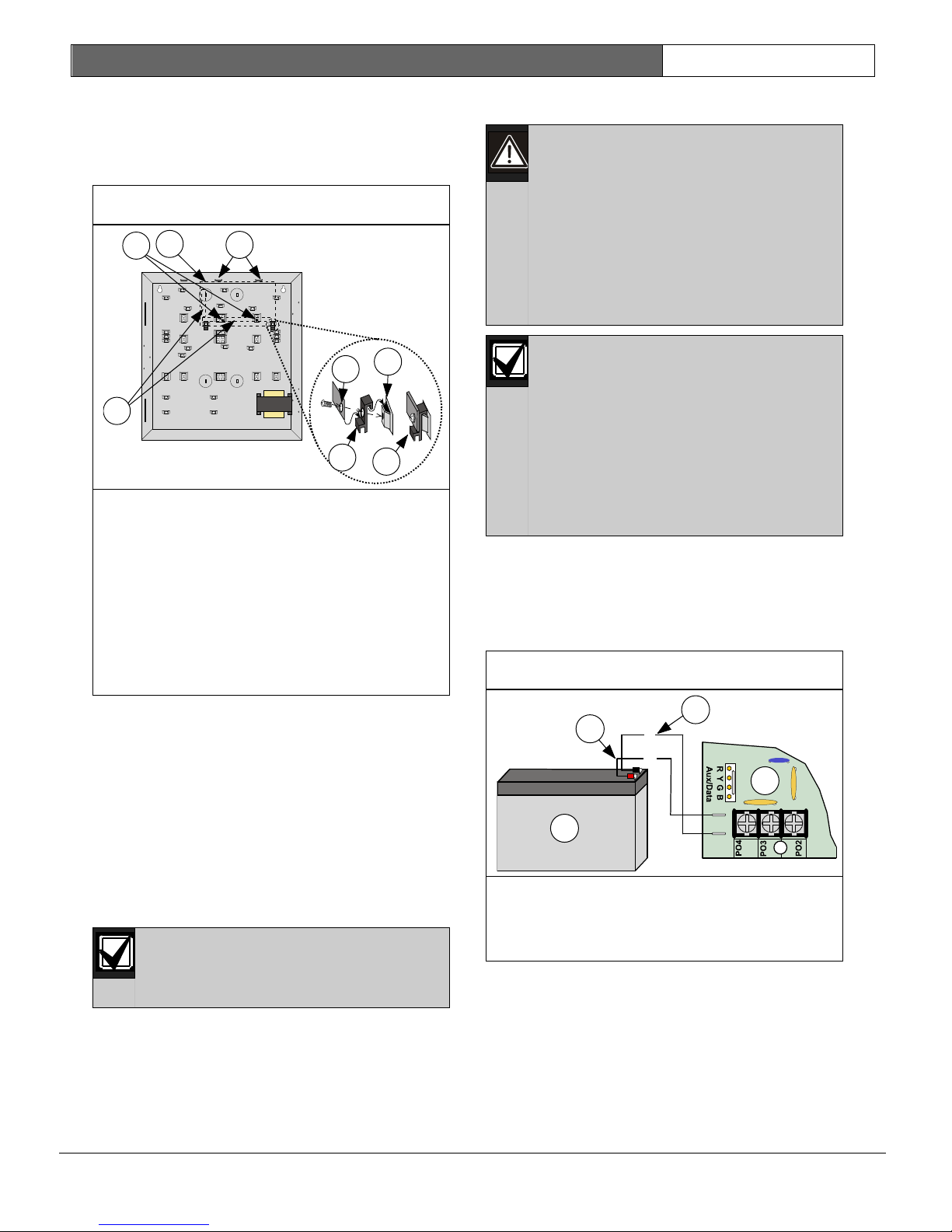
Figure 2: Control Panel Board Mounting
Figure 3: Standby Battery Connections
1
2
=
4
5
6
7
3
8
BATT+
BATT-
(+)
(-)
1
2
3
4
2.1.3 Control Panel Board Installation
1. Place the control panel board clips on the
appropriate standoffs in the enclosure. See
Figure 2.
1- Install support standoffs (0.08 mm) here
2- Control panel board location
3- Place edge of control panel board between
slots
4- Corner of control panel board
5- Control panel board clip
6- Enclosure standoff
7- Completed assembly
8- Control panel board terminal block
locations
EN | 12
2.1.6 Standby Battery Installation
High current arcs are possible. The
red (+) battery lead and the control
panel’s “BATT +” connector can
create high current arcs if shorted to
terminals or enclosure. Use caution
when working with the red lead and
the control panel’s “BATT +”. Always
disconnect the red lead from the
battery before removing the red lead
from the control panel.
Replace the standby battery every 3
to 5 years under normal use.
Exceeding the maximum output
ratings, or connecting the control
panel to an outlet that is routinely
switched off, causes heavy
discharges. Routine heavy
discharges can lead to premature
battery failure. Record the date of
installation directly on the battery.
When the standby battery and the transformer
connections are made, the control panel charges
the standby battery as you finish the installation.
See Figure 3 for details when installing the
standby battery.
Slide the control panel board into the slots at the
top of the enclosure, and then secure it with the
two screws provided. See Figure 2.
2.1.4 Ground and Transformer Connection
1. Connect the green/yellow earth ground wire
from the earth ground stud to the control
panel as shown in Figure 65 on page 129.
2. Connect the orange and yellow wires from
the transformer to the control panel as shown
in Figure 65 on page 129.
2.1.5 Mains Connection
1- Standby battery
2- Control panel board
3- Black (-) line
Make sure you have a good earth
ground before completing the
following steps.
4- Red (+) line
Follow all electrical codes when routing the AC
Mains power connection to the control panel.
DS7200V2-EXP | Installation Guide | 2. System Installation
and Setup
Bosch Security Systems, Inc. | 04/12 | F01U253045-02
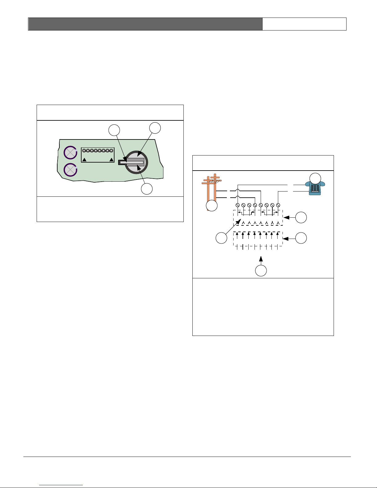
Figure 4: RAM Backup Battery
REMOVE
Figure 5: RJ31X/RJ38X Wiring
AUXILIARY
2
1
3
3
4
5
6
1
2 3
6
7 8
1 2
3
4 5
6 7
8
R1
T1R
T
4
5
T
R
T1
R1
1
2
2.1.7 RAM Backup Battery Installation
The control panel uses a 3 V coin-type lithium
battery to save system settings, including
date/time and programming settings.
Remove the insulator tab from between the
battery and battery clip before completing
system installation.
1- RAM Backup Battery
2- Battery Clip
3- Insulator -
EN | 13
2.1.8 Telephone Connections
See System Status LED on page 40 for a complete
function description.
1. To prevent jamming of signals, wire the
RJ31X jack or RJ38X jack to support line
seizure as shown in Figure 5.
2. Install the jack on the street side of the
phone switch, wired ahead of any PBX
equipment. Line seizure temporarily
interrupts normal phone usage while the
communicator transmits data.
3. Confirm that the panel seizes the line,
acquires dial tone, reports correctly to the
receiver, and releases the phone line to the
in-house phone system.
1- Outside Telco (PSTN)
2- Premises telephone
3- RJ31X or RJ38X jack
4- Telco connector block
5- Phone line connections to control panel
6- Bar short removed on Telco connector
block insertion – positions 1 & 4 and 5 & 8
4. Connect the telephone cord’s flying leads to
the telephone terminals (Red to R; Gray to
R1; Brown to T1; Green to T). The terminals
are located on the right side of the control
panel board.
5. Plug the other end of the cord to the RJ31X
jack or RJ38X jack.
DS7200V2-EXP | Installation Guide | 2. System Installation
and Setup
Bosch Security Systems, Inc. | 04/12 | F01U253045-02
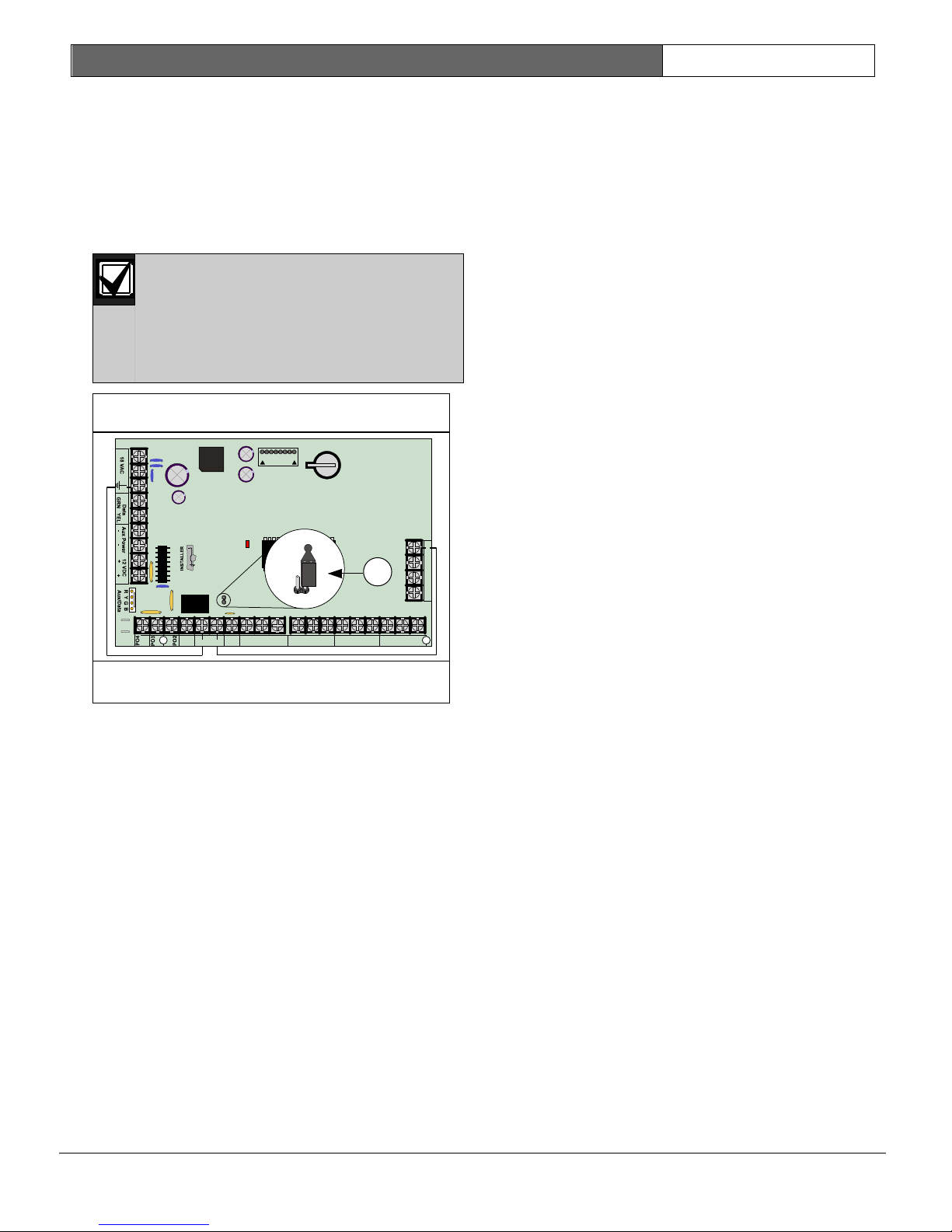
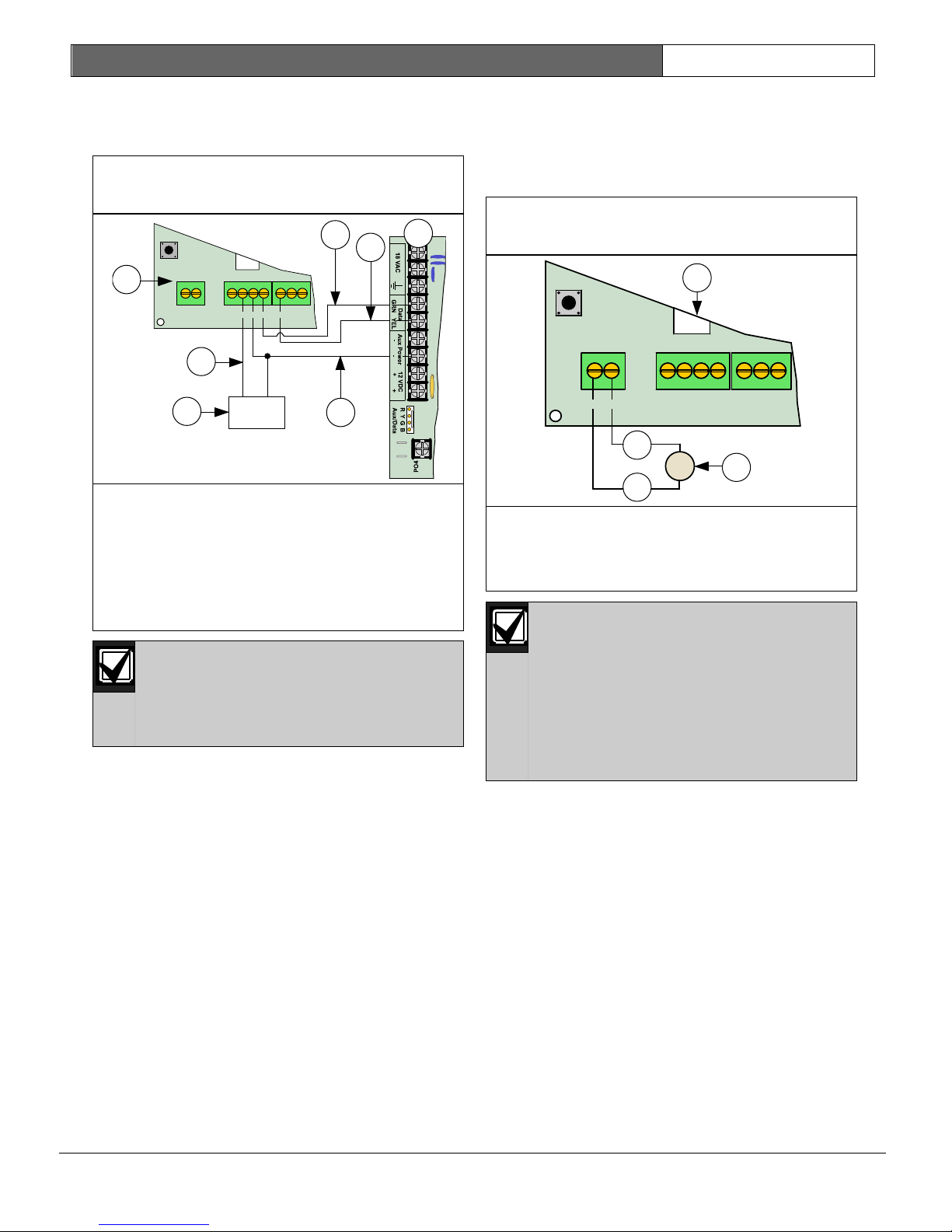
Figure 6: Ground Start
BATT+
BATT-
ALRM
+
PO1
L-1
SMK
+
L-2COM
L-4COML-3 L-6COML-5
L-8COML-7
T
T1
R1
AUXILIARY
PO1 SELECT
STATUS
R
B
A
1
2.1.9 Ground Start
Some telephone systems require a momentary
ground input to initiate a dial tone. To interface
with a ground start system, wire PO 1 as shown
in Figure 6. The PO 1 Jumper must be open.
Program PO 1 for Ground Start. See
Programmable Output 1 (PO 1) on page 21 for
programming instructions.
Connect a proper earth ground
reference to the earth ground
terminal.
Ground Start is not intended for use
in fire or combined fire/burglary
applications.
1- Place PO1 jumper in OPEN position as
shown
2.1.10 Phone Line Fault
The control panel has a circuit that tests the
phone line for voltage. The normal voltage on a
telephone line is approximately 48 VDC (24 VDC
for some phone systems). The phone line monitor
senses trouble when the voltage drops low
enough (between 1 and 3 V).
If the control panel senses trouble for 40 sec, it
begins a phone line trouble response.
Programming determines the response type. See
“Phone Line Fault Response Options” in the
DS7200V2 Expert Programming Guide (P/N:
4998153891) for details.
Bad line may test OK: The telephone line test
circuit uses the voltage level to test the status of
the phone line. In some instances, a given
telephone line might be out of service without
affecting the voltage on the line. The phone line
monitor cannot recognize this trouble condition.
EN | 14
2.1.11 Communication Failure (Comm Fail)
The control panel routes reports to two routing
destinations. Each destination can be
programmed with two phone numbers or IP
addresses.
The numbers in {} are the numbers assigned to
control panel events.
Communication Attempt Tables on page 123
shows the circumstances when Communication
Failure Events are created. When a Comm Fail
occurs, the control panel responds as follows:
1. Clear (dump) the initiating report and any
pending reports from the dialer buffer for the
destination where the Comm Fail event
occurred.
2. Create a Comm Fail {69} or Alternate Comm
Fail {70} report that includes the Destination
Number (1 or 2). The Alternate Comm Fail
report is used when an alternate
communications path is used (for example,
network communication).
3. The Comm Fail, Comm Restoral {71},
Alternate Comm Restore {72} reports follow
the System Status Reports routing.
4. If the Comm Fail occurred on Destination 1
and System Status Reports routing is set to
Destination 2 or set to Destination 2 on
Destination 1 fail, then send Comm Fail
report.
5. If the Comm Fail occurred on Destination 1
and System Status Reports routing is set to
Destination 1 then send a Comm Restore
report with the next report for destination 1.
6. If the Comm Fail occurred on Destination 2
and System Status Reports routing is set to
Destination 1, then send Comm Fail report.
7. If the Comm Fail occurred on Destination 2
and System Status Reports routing is set to
Destination 2 then send a Comm Restore
report with the next report for Destination 2.
8. If a Comm Fail report is sent successfully to
the other destination, a Comm Restore event
should be sent when there is a successful
communication on the failed destination.
DS7200V2-EXP | Installation Guide | 2. System Installation
and Setup
Bosch Security Systems, Inc. | 04/12 | F01U253045-02
Table 3: Keypad Address Pin Settings
Keypad Address Pins
Keypad
Addres
s
1 2 4 8 16
MODE
ON
ON
ON
ON
ON ON
ON
ON
ON
ON
ON
ON
ON ON
ON
ON ON ON
ON
ON
ON
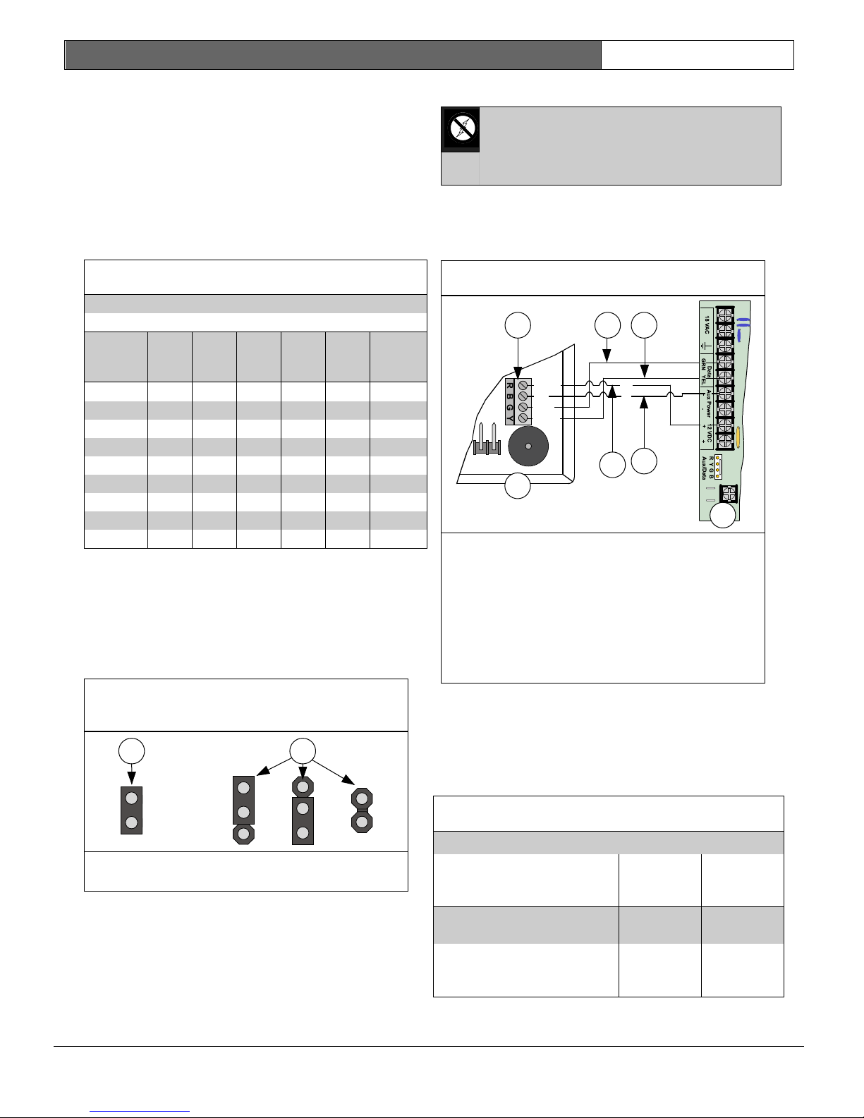
Figure 7: Keypad Jumper Plug
Configuration
Figure 8: Keypad to Control Panel Wiring
7- Control panel board
Table 4: Keypad to Control Panel Wire Length
0.8 mm
(#22
AWG)
1.2 mm
(#18
AWG)
1
2
BATT+
BATT-
7
Data In
Data Out
+12 VDC
Com
1
2 3 4
6
5
(+)
(-)
2.2 Arming Device Installation
The Door Access Control Module (DACM) is also
an arming device. See Door Access Control Module
(DACM) on page 38 for more information.
2.2.1 Keypad Addressing
Keypads 1 to 8 are assigned to Data Bus
Addresses 1 to 8.
Table 3 shows the correct address setting for
each keypad address.
0* OFF OFF OFF OFF OFF OFF
1
2 OFF
3
4 OFF OFF
5
6 OFF
7
8 OFF OFF OFF
* Address 0 is reserved for the Installer Keypad.
This keypad is not intended for permanent
installation and should remain with the
installer/service technician.
Some keypads use jumper plugs to set the
address. See Figure 7 for correct jumper plug
orientation.
OFF OFF OFF OFF
OFF OFF OFF
OFF OFF OFF
OFF OFF
OFF
OFF OFF
OFF OFF
OFF OFF
OFF
EN | 15
2.2.2 Keypad Installation
Keypads contain static-sensitive
components. Follow anti-static
procedures when handling the
keypads.
Consult your keypad’s installation manual for
complete installation instructions. Keypads
connect to the control panel in parallel as shown
in Figure 8.
1- DS7447E/DS7445i Keypads, or
DS7447V2/DS7445V2 Keypads
2- Keypad terminal block
3- Green data wire
4- Yellow data wire
5- Red (+12 VDC) wire
6- Black (-12 VDC) wire
You can use either one of the Aux Power (-)
terminals and either one of the 12 VDC (+)
terminals when connecting devices to the control
panel.
See Table 4 for control panel data bus-to-keypad
wire length requirements.
1- Jumper plug ON position
2- Jumper plug OFF positions
Control Panel to Keypad 305 m
Control Panel to Keypad
using an External Power
Supply
(1000 ft)
305 m
(1000 ft)
610 m
(2000 ft)
610 m
(2000 ft)
DS7200V2-EXP | Installation Guide | 2. System Installation
and Setup
Bosch Security Systems, Inc. | 04/12 | F01U253045-02
Figure 9: Keypad to Control Panel Wiring
(External Power Supply)
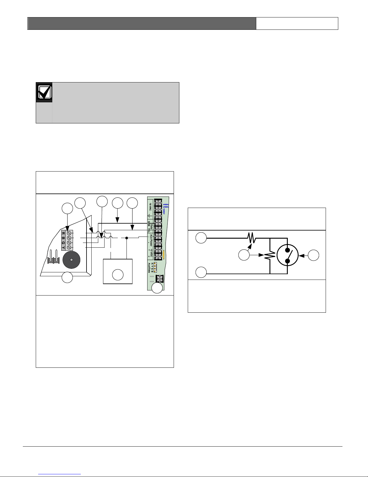
Figure 10: Keyswitch: Tamper Wired
Zone Configuration
1- Zone input
Data In
Data Out
+12 VDC
(+)
(-)
Com
(+)
(-)
1
2
3
4
8
5
6
BATT+
BATT-
7
3
1
2
4
See Power Outputs on page 8 to determine the
total power available for your system. You might
need to add one or more external power supplies
for the number of keypads you want to use. See
Figure 9 to connect an external power supply to a
keypad.
Do not tie the black (-) output to
earth ground when using an external
power supply. A ground fault
condition is reported if black (-) is
grounded.
You can use either one of the Aux Power (-)
terminals when connecting to the control panel.
Figure 9 shows the common from the external
power supply connected to both the keypad’s
common terminal and the control panel’s Aux
Power (-) terminal.
EN | 16
2.2.4 Keyswitch Overview
You can connect a maintained or momentary
contact arming device to arm or disarm any of the
areas in the system. The keyswitch is connected
to an on-board or off-board zone’s sensor loop.
The control panel offers a wide variety of
keyswitch arming options. The default keyswitch
configuration is tamper-wired. See “Controlled
Keyswitch Types” in “Zone Function
Configuration” in the DS7200V2 Expert
Programming Guide (P/N: 4998153891) for
alternative keyswitch configurations.
Outputs can be programmed to activate LEDs,
sound alarm outputs, or activate strobes to
indicate arming status for keyswitch arming
stations. See Output Parameters on page 86 for
more information.
2.2.5 Keyswitch Installation
Keyswitch Wiring – Tamper Wired Zone
Configuration
For maintained or momentary operation, wire the
keyswitch as shown in Figure 10.
1- DS7447E/DS7445i Keypads, or
DS7447V2/DS7445V2 Keypads
2- Keypad terminal block
2- Common
3- 2.2 kΩ resistors
4- Keyswitch
3- Red (+12 VDC) wire
4- Black (-12 VDC) wire
5- Green data wire
6- Yellow data wire
7- Control panel board
8- External 12 VDC power supply
2.2.3 Keypad Supervision
The control panel supervises communication to
the keypad. If it fails to communicate with the
keypad, it sends a “DBus Missing” {125} report.
DS7200V2-EXP | Installation Guide | 2. System Installation
and Setup
Bosch Security Systems, Inc. | 04/12 | F01U253045-02
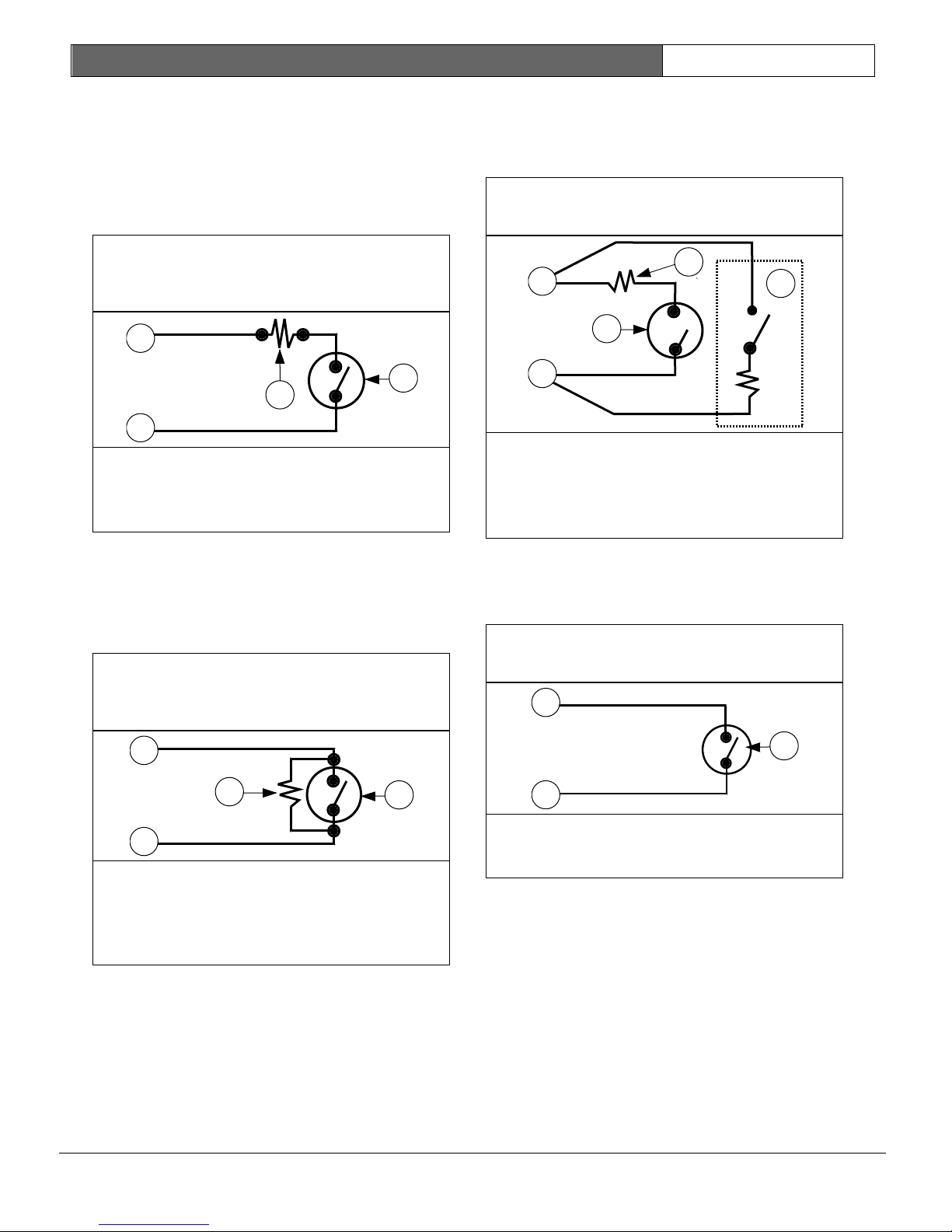
Figure 11: Maintained Keyswitch:
Single EOL Resistor
Configuration
Figure 12: Momentary Keyswitch:
Single EOL Resistor
Configuration
Figure 13: Keyswitch: Zone Doubled
Configuration
Figure 14: Keyswitch: No EOL Resistor
Configuration
3
1
2
4
3
4
1
2
1
2
3
Keyswitch Wiring – Single EOL Configuration
For maintained switches, connect the EOL
resistor for the zone at the keyswitch so that the
switch opens the circuit when it operates. A
short on the circuit produces an alarm if the area
is armed and a trouble if it is disarmed. See
Figure 11.
EN | 17
Keyswitch Wiring – Zone Doubled
Configuration
For maintained or momentary operation, wire the
keyswitch as shown in Figure 13.
4
1
3
5
2
1- Zone input
2- Common
3- 2.2 kΩ resistor
4- Keyswitch (Open on circuit arms area)
For momentary switches, connect the EOL
resistor for the zone at the keyswitch so that the
switch shorts the resistor when it operates. An
open on the circuit produces an alarm if the area
is armed and a trouble if it is disarmed. See
Figure 12.
1- Zone input
2- Common
3- 2.2 kΩ resistor
4- Keyswitch (Short on circuit toggles arming
state)
1- Zone input
2- Common
3- Second zone wiring
4- 2.2 kΩ or 3.65 kΩ resistor
5- Keyswitch
Keyswitch Wiring – No EOL Resistor
Configuration
For maintained or momentary operation, wire the
keyswitch as shown in Figure 14.
1- Zone input
2- Common
3- Keyswitch
DS7200V2-EXP | Installation Guide | 2. System Installation
and Setup
Bosch Security Systems, Inc. | 04/12 | F01U253045-02
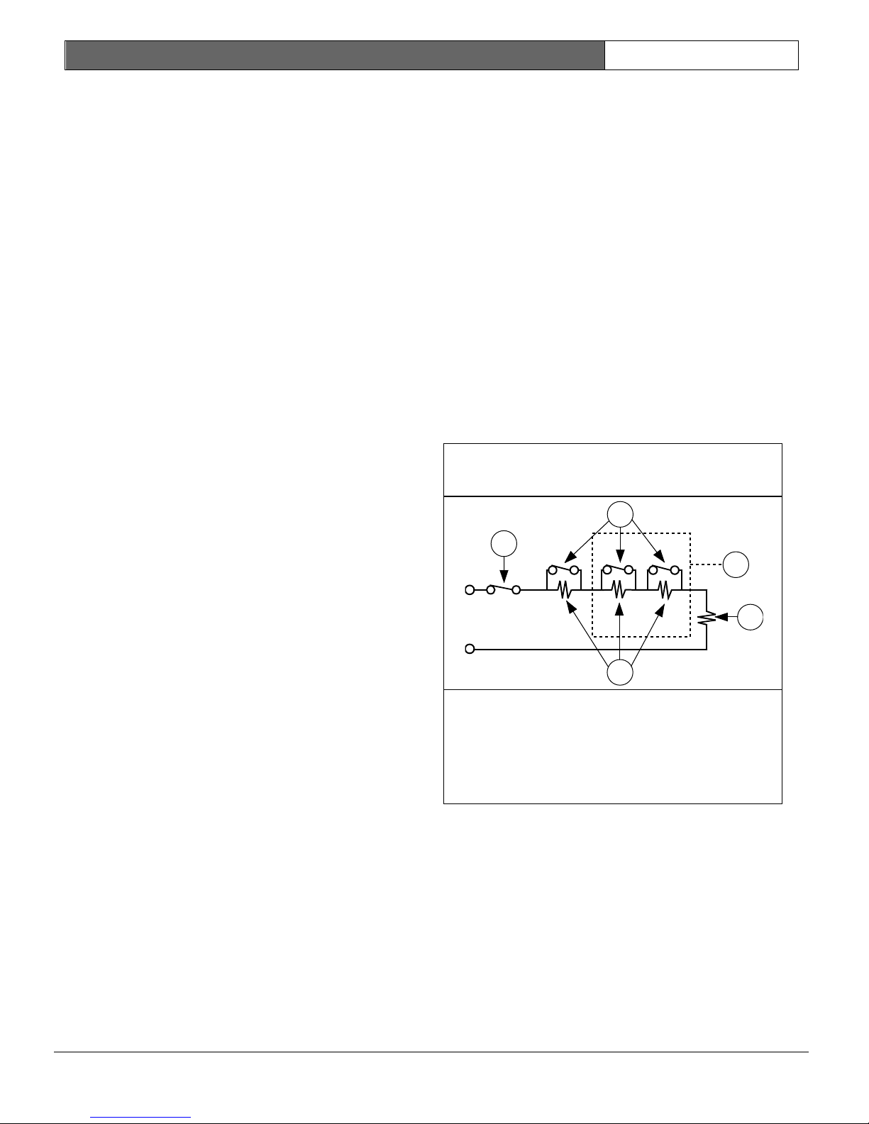
Figure 15: Tamper-Wired Zone
Configuration
3
4
1
2
5
2.2.6 Silencing an Alarm with a Keyswitch
Momentary Keyswitch: To silence alarms (stop
Alarm output), operate the keyswitch. If the area
is armed, operating the keyswitch to silence the
alarm also disarms the area. If the area is
disarmed, operating a momentary keyswitch to
silence the alarm does not arm the area.
Maintained Keyswitch: If the area is armed, turn
the keyswitch to the disarmed position. The
control panel disarms the area and silences the
alarm. If the area is disarmed, turn the keyswitch
to the armed position (the control panel does not
arm) and then return to the disarmed position.
2.2.7 Exit Terminator Button
When the Keyswitch Zone Function Options 1
parameter (see “Options 1, Zone Function ##” in
the DS7200V2 Expert Programming Guide
[P/N: 4998153891]) is set to 15, the input
functions as an exit terminator button. This zone
function activates in the same manner as the
momentary keyswitch. When Exit Delay is active,
operating the exit terminator button terminates
Exit Delay and immediately arms the control
panel. If Chime Mode is enabled and Exit Delay is
not active, pressing the exit terminator button
activates the chime tone and the button
functions as a doorbell.
EN | 18
2.3 On-board Sensor Loop Setup
2.3.1 Overview
The control panel provides eight on-board sensor
loops (L-1 to L-8). Each sensor loop operates
independently and does not interfere with the
operation of the others.
The default End-of-Line (EOL) resistor selection
for the on-board sensor loops is the single alarm
contact tamper-wired configuration.
See “Global Zone Configuration” in the DS7200V2
Expert Programming Guide (P/N: 4998153891) to
modify the on-board sensor loop EOL resistor
configuration.
2.3.2 Tamper-Wired Zone Configuration
The on-board sensor loops can be used as
tamper-wired zones to report tamper conditions
when the zone has become open or shorted.
See Figure 15 to wire a sensor loop as a tamper-
wired zone.
1- Tamper contact
2- Alarm contact
3- Multiple alarm contact configuration only
(5 contacts max)
4- 2.2 kΩ EOL resistor
5- 2.2 kΩ alarm resistor
DS7200V2-EXP | Installation Guide | 2. System Installation
and Setup
Bosch Security Systems, Inc. | 04/12 | F01U253045-02
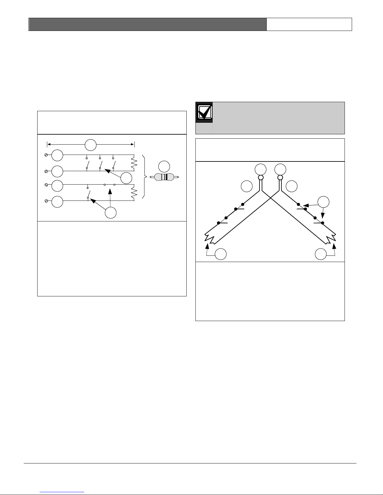
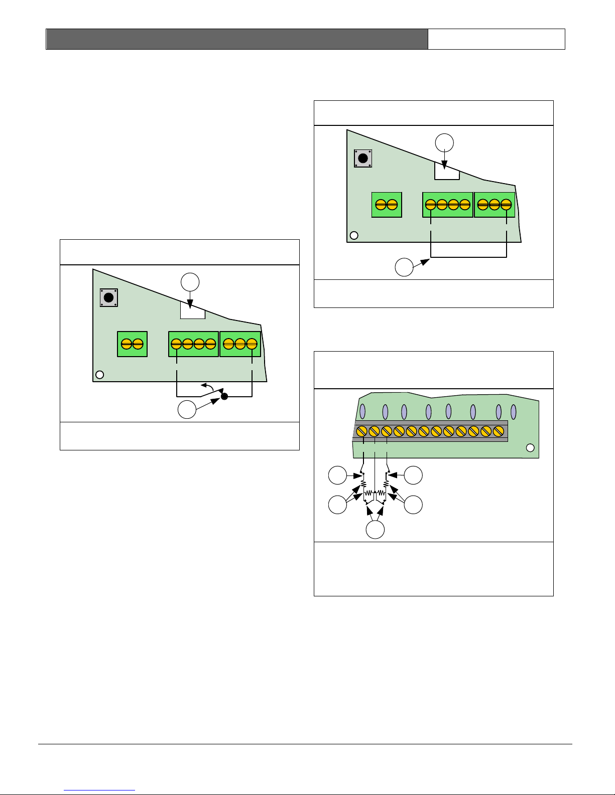
Figure 16: Single Zone Sensor Loop
Wiring
Figure 17: On-board Doubled Zone
Sensor Loop Wiring
5
4
2
3
1
6
7
8
6
5
2
3
1
7
4
2.3.3 Single Zone Configuration (Loops 1-8)
When wiring the on-board sensor loops in the
single zone configuration, install the resistor of
the appropriate value (2.2 kΩ resistors are
provided) at the far end of the sensor loop to
provide a reference for supervision. You can
connect dry contact sensing devices in series
(Normally-Closed) and/or in parallel (NormallyOpen) to any of these loops (see Figure 16).
EN | 19
2.3.4 Doubled Zone Configuration
When wiring the on-board sensor loops in the
doubled zone configuration, install the resistors
of the appropriate value (2.2 kΩ and 3.65 kΩ) as
shown in Figure 17. The control panel can be
configured to function with either Normally-Open
or Normally-Closed contacts. Normally-Closed
contacts are recommended.
Each sensor loop is monitored as a
separate zone.
1- Sensor loop terminal
2- Common
3- Sensor loop terminal
4- Common
5- 100Ω maximum
6- 2.2 kΩ EOL resistor (P/N: 47819)
7- Normally-Open contacts
8- Combination of Normally-Open contacts and
Normally-Closed contacts
Loop resistance limits the number of NormallyOpen and/or Normally-Closed detection devices
that each sensor loop can supervise. The total
resistance for wire length and contacts, minus
the end-of-line resistor, must not exceed 100 Ω.
1- Common
2- Sensor Loop 1 to Sensor Loop 8
3- On-board Locations 1 to 8
4- Alarm Contacts
5- 3.65 kΩ EOL resistor
6- 2.2 kΩ EOL resistor
7- On-board Locations 9 to 16

DS7200V2-EXP | Installation Guide | 2. System Installation
and Setup
Bosch Security Systems, Inc. | 04/12 | F01U253045-02
Figure 18: Single Zone Sensor Loop
Wiring
(No EOL)
Figure 19: 4-wire Smoke Detector
(Tamper-wired)
5
4
2
3
1
6
7
BATT+
BATT-
ALRM
+
PO1
SMK
+
PO1 SELECT
4
1
2
3
5
6
A
B COM
L-1
2.3.5 No EOL Zone Configuration
See Figure 18 when wiring a zone with no EOL
resistors.
1- Sensor loop terminal
2- Common
3- Sensor loop terminal
4- Common
5- 100 Ω maximum
6- Normally-Open contacts
7- Normally-Closed contacts
EN | 20
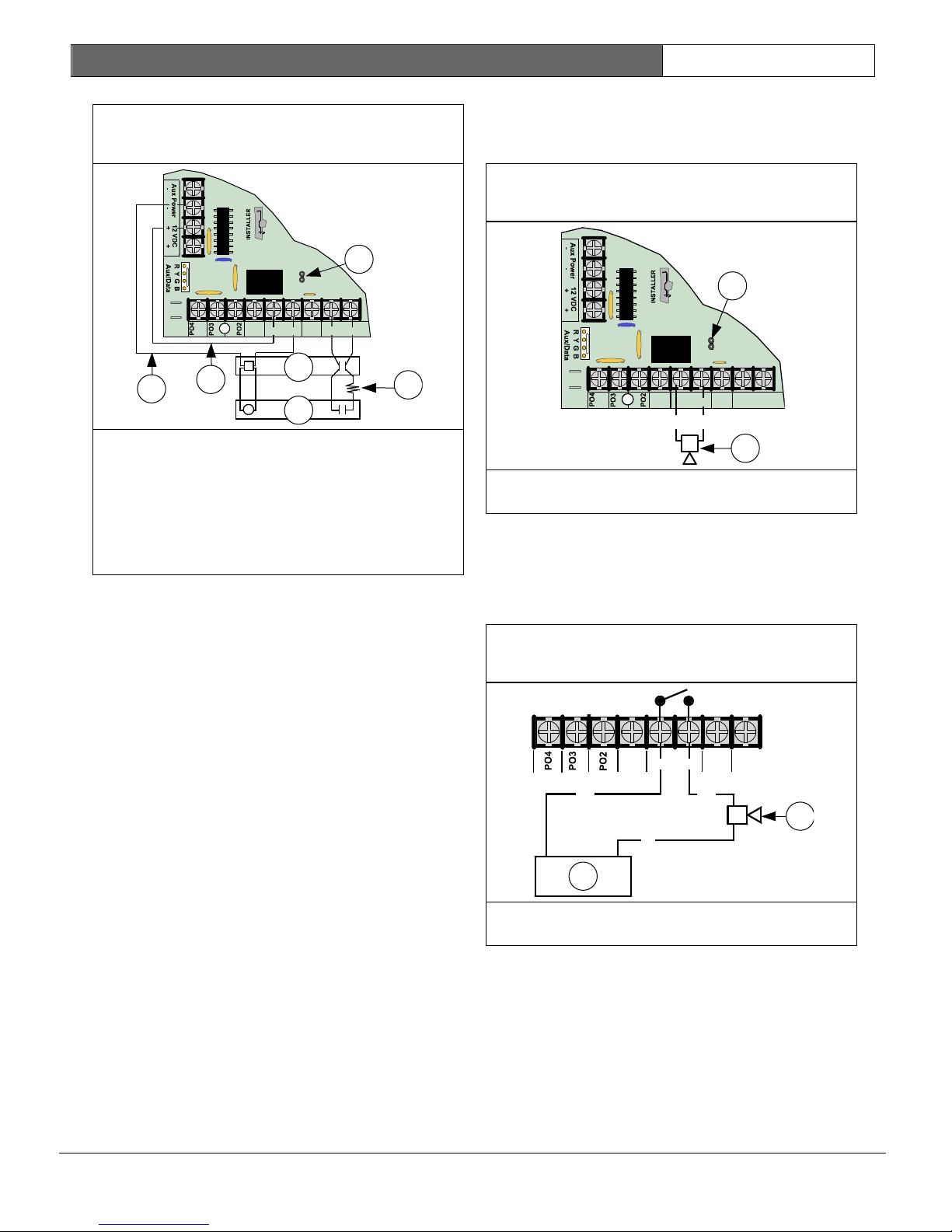
2.3.6 Four-Wire Smoke Detector
Configuration
A four-wire smoke detector can be connected to
any of the control panel’s on-board sensor loops
(L-1 to L-8). A four-wire smoke detector must use
a relay module to interrupt power to the detector
in order for the detector to reset.
Configure the output controlling the relay as
Output Function 1|13 “Fire Verification” (see
Output Parameters on page 86 for more
information).
Make loop connections to L-X (where X = Loop #)
and COM terminals. See Figure 19, and Figure 20
on page 21.
1- Remove jumper plug from PO 1 SELECT
jumper
2- 2.2 kΩ alarm resistor
3- 2.2 kΩ EOL resistor
4- Smoke detector
5- AUX (+)
6- AUX (-)
DS7200V2-EXP | Installation Guide | 2. System Installation
and Setup
Bosch Security Systems, Inc. | 04/12 | F01U253045-02
Figure 20: 4-wire Smoke
Detector (Single EOL Resistor)
Figure 21: PO 1 Wiring (PO 1 Jumper
Shorted)
Figure 22: PO1 Dry Contact Wiring (No
PO 1 Jumper)
BATT+
BATT-
ALRM
+
PO1
SMK
+
PO1 SELECT
2
5
6
4
3
A
B
COM
1
L-1
PO1
L-1
SMK
+
ALRM
+
(+) (-)
A B
(+) (+)
(-)
2
1
1- Remove jumper plug from PO 1 SELECT
jumper
2- 2.2 kΩ EOL resistor
3- EOL200 End-of-Line Module
4- DS250 with MB4W Base
5- AUX (+)
6- AUX (-)
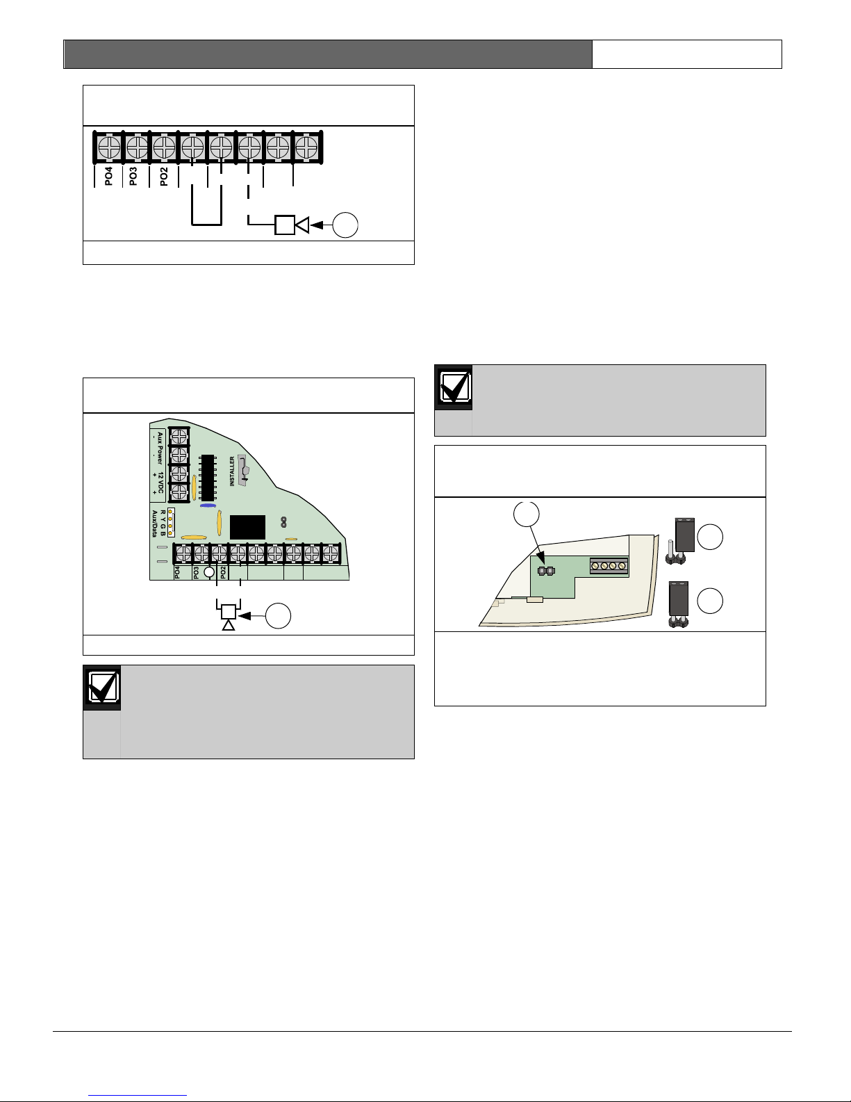
2.4 On-board Output Setup
2.4.1 Overview
The control panel has four on-board
programmable outputs (PO 1 to PO 4).
Programmable Output 2 (PO 2) can be
configured as a supervised siren driver. See
“Global Output Options” in the DS7200V2 Expert
Programming Guide (P/N: 4998153891) for
programming instructions. When programmed as
a siren driver, PO 2 draws power from the ALRM
+ terminal. When connected to a 4 Ω
horn/speaker, PO 2 draws 380 mA of current.
When connected to an 8 Ω horn/speaker, it draws
330 mA of current. Use the appropriate current
draw in your total alarm power calculation.
EN | 21
2.4.2 Programmable Output 1 (PO 1)
By default, PO 1 is the Bell output, and the PO 1
SELECT jumper should be shorted. See Figure 21.
1
PO1 SELECT
BATT+
BATT-
ALRM
SMK
PO1
+
A
(+)
(-)
L-1
B
COM
+
2
1- Short PO 1 SELECT jumper with jumper plug
2- Audible notification appliance
PO 1 can also be configured as an alarm power
output (short PO 1 SELECT jumper). PO 1
operates as a dry contact, Normally-Open relay
with PO 1 SELECT jumper open. See Figure 22,
and Figure 23 on page 22 for details.
1- Audible notification appliance
2- DC power source
DS7200V2-EXP | Installation Guide | 2. System Installation
and Setup
Bosch Security Systems, Inc. | 04/12 | F01U253045-02
Figure 24: PO 2 to PO 4 Wiring
Figure 25: RF3227E Address Jumper
Settings
PO1
L-1
SMK
+
A B
(+)
1
ALRM
+
R
B G
Y
ADDR
1
2
3
Figure 23: PO 1 Positive Alarm Trigger
Wiring
1- Audible notification appliance
2.4.3 Programmable Outputs 2 to 4 (PO 2 to
PO 4)
PO 2 can be used with ALRM+ as a supervised
siren driver. Connect an approved 4 or 8
speaker. Alternatively, PO 2 can sink up to 500
mA 12 VDC. See Figure 24.
EN | 22
If PO 1 to PO 4 do not provide the alarm output
you expect, do the following:
Check the programming for Programmable
Outputs in Output Parameters on page 86.
Check “Zone Function Configuration” in the
DS7200V2 Expert Programming Guide
(P/N: 4998153891) to verify the zones you are
activating are programmed for alarm output.
2.5 RF3227E RF Receiver Setup
For complete installation instructions regarding
the RF3227E Premises RF Receiver, see the
RF3227E Installation Guide (P/N: 4998122415).
2.5.1 RF Receiver Addressing
Set the RF3227E’s address by placing the
address jumper pin as shown in Figure 25.
Remove power from the system and
RF receiver so that RF receiver
address changes can take effect.
PO1 SELECT
BATT+
BATT-
(+)
ALRM
+
(-)
PO1
A B
SMK
L-1
COM
+
1
1- Audible notification appliance
If PO 2 is configured as a supervised
siren driver (in combination with the
ALRM + terminal), you must connect a
4 or 8 speaker to PO 2 to clear the
speaker supervision trouble.
PO 3 and PO 4 can be configured for Alarm
Output. These outputs can sink up to 500 mA
12 VDC each.
Defaults for PO 2 to PO 4 are as follows:
PO 2: 1|6 (Strobe)
PO 3: 0|1 (Armed: All, Perimeter Only, Partial On)
PO 4: 2|13 (Ready to Arm)
See Output Parameters on page 86 for
programming instructions.
1- RF receiver address jumper pins
2- RF Receiver #1 (Address 50) jumper plug OFF
(default position)
3- RF Receiver #2 (Address 51) jumper plug ON
DS7200V2-EXP | Installation Guide | 2. System Installation
and Setup
Bosch Security Systems, Inc. | 04/12 | F01U253045-02
Figure 26: RF3227E to Control Panel
Wiring
Figure 27: Standard DX2010 Installation
Locations
BATT+
BATT-
6
1
2 3
4
5
R
G
B
Y
1
3
4
2
5
2.5.2 RF Receiver to Control Panel Wiring
The RF3227E contains static-sensitive
components. Follow anti-static
procedures when handling this
module.
Wire the RF3227E to the control panel as shown
in Figure 26. When power is applied to the
system, the red LED at the center of the RF3227E
lights.
EN | 23
2.6 Off-board Sensor Loop Setup
(DX2010)
2.6.1 DX2010 (DX2014) Overview
The DS7240V2 supports up to 5 DX2010 Input
Expanders. The DS7220V2 supports up to 3
DX2010 Input Expanders.
Each DX2010 provides eight sensor loops. See
Location ##, Zone Function on page 83 for
information on how the DX2010 sensor loops are
assigned to zone locations.
• DX2014 Input Expander: A DX2010 mounted
inside a plastic enclosure with tamper switch
for remote installation.
• Current Draw without Aux Output
Terminals: 35 mA Standby
• Current Draw with Aux Output Terminals:
135 mA maximum with 100 mA of connected
accessories.
2.6.2 DX2010 Installation
The DX2010 contains static-sensitive
components. Follow anti-static
procedures when handling this
module.
1- RF3227E terminal block
2- Red wire (+) or (R)
3- Black wire (-) or (B)
Up to three DX2010 modules can be installed in
the control panel’s enclosure (two on interior
side walls of enclosure and one on back wall of
enclosure). See Figure 27 and Figure 28 for
installation locations.
4- Green data wire (G)
5- Yellow data wire (Y)
6- Control panel board
You can use either one of the Aux Power (-)
terminals and either one of the 12 VDC (+)
terminals when connecting devices to the control
panel.
2.5.3 RF Receiver Programming
See Data Bus Device Parameters on page 99 for
programming instructions.
2.5.4 RF Reciever Supervision
The control panel supervises communication to
the RF receiver. If it fails to communicate with
the RF receiver, it sends a “DBus Missing” {125}
report.
1- Control panel board location
2- Standard DX2010 mounting locations
3- DX2010 module
4- Enclosure wall
5- Screws (supplied with DX2010)
DS7200V2-EXP | Installation Guide | 2. System Installation
and Setup
Bosch Security Systems, Inc. | 04/12 | F01U253045-02
Figure 28: Optional DX2010 Mounting
Locations
Table 5: DX2010 to Control Panel Wire
Length
Power
Source
08 mm
(#22
AWG)
1.2 mm
(#18
AWG)
Used
(98.4 ft)
(249.3 ft)
Table 6: DX2010 to External Power Supply
Wire Length
08 mm
(#22 AWG)
1.2 mm
(#18 AWG)
Figure 29: DX2010 to Control Panel
Wiring
5
6
2
1
BATT+
BATT-
2
3
4
5
6
1
+OUT- TMPR 1 COMR B YG
1- Control panel board location
2- DX2010 optional mounting location
Up to five DX2014 modules can be connected to
the DS7240V2 (up to 2 on a DS7220V2). See
Figure 29 for wiring details.
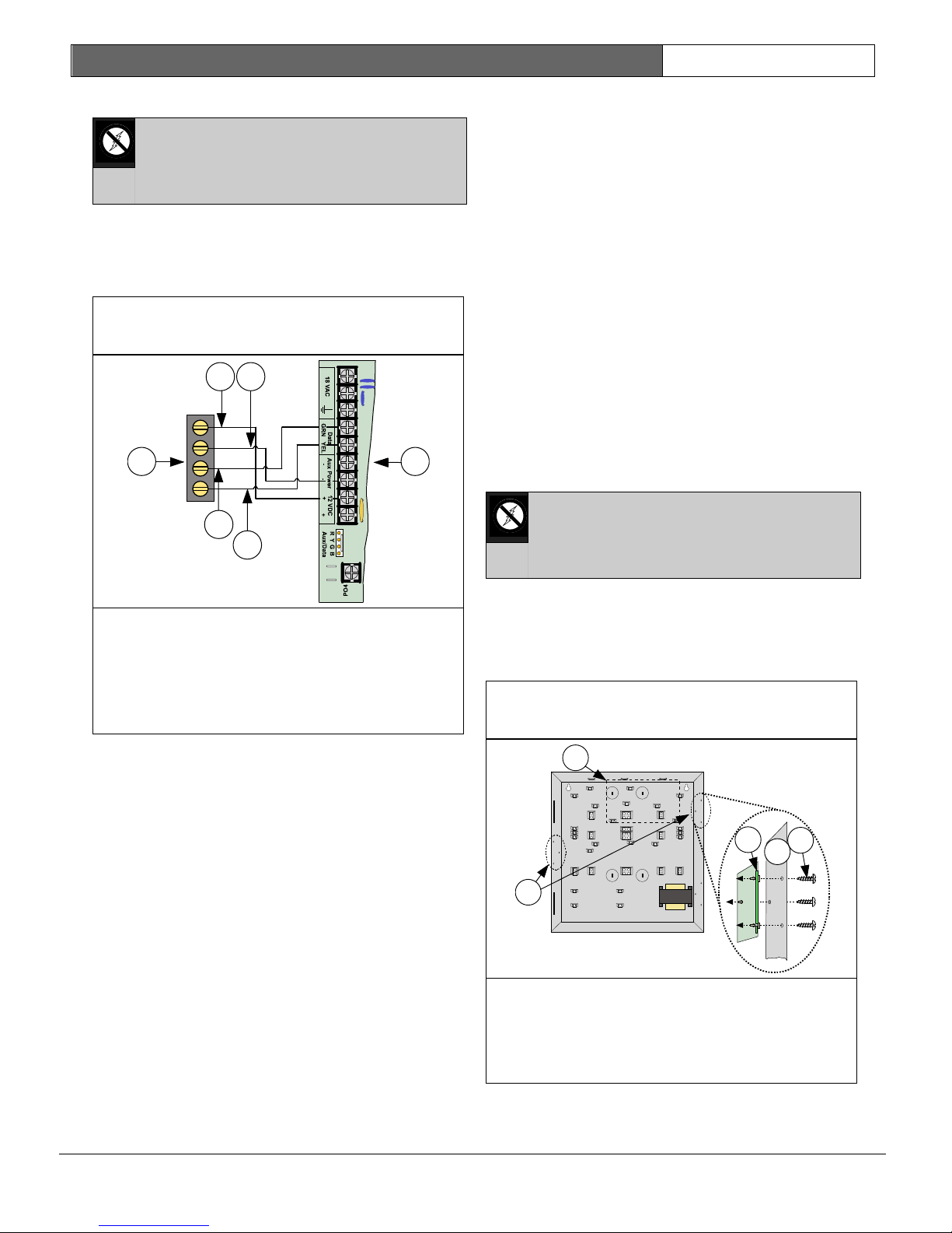
2.6.3 DX2010 Wiring
Do not use twisted pair or shielded cable when
wiring the DX2010.
See the following tables for Data Bus wire length
requirements.
Aux Output
Not Used
Aux Output
Aux Output
Used or Not
Used
Control
Panel
External
Power
Supply
305 m
(1007.7 ft)
30 m
305 m
(1007.7 ft)
610 m
(2001 ft)
76 m
610 m
(2001 ft)
EN | 24
Connect the control panel’s Data and Aux Power
terminals to the DX2010 as shown in Figure 29.
If the DX2010’s Aux Output (“+Out-“
terminals) is used as an auxiliary
power source, the DX2010’s “R” and
“B” wires must be “home-run” to
either the control panel or to an
available power supply. Do not use a
daisy-chain wire configuration.
1- DX2010 module
2- Green (G) data wire
3- Yellow (Y) data wire
4- Black (-) wire
5- Red (+) wire
6- Control panel board
You can use either one of the Aux Power (-)
terminals and either one of the 12 VDC (+)
terminals when connecting devices to the control
panel.
Aux Output
Not Used
Aux Output
Used
305 m
(1007.7 ft)
30 m
(98.4 ft)
610 m
(2001 ft)
76 m (249.3
ft)
DS7200V2-EXP | Installation Guide | 2. System Installation
and Setup
Bosch Security Systems, Inc. | 04/12 | F01U253045-02
Figure 30: DX2010 to Control Panel
Wiring (External Power Supply)
Figure 31: DX2010 Auxiliary Output
Wiring
BATT+
BATT-
2
3
4
7
+OUT- TMPR 1 COM
B
Y
G
5
(+)
(-)
R
6
1
TMPR 1 COM
R
B
G Y
+OUT-
2
3
4
1
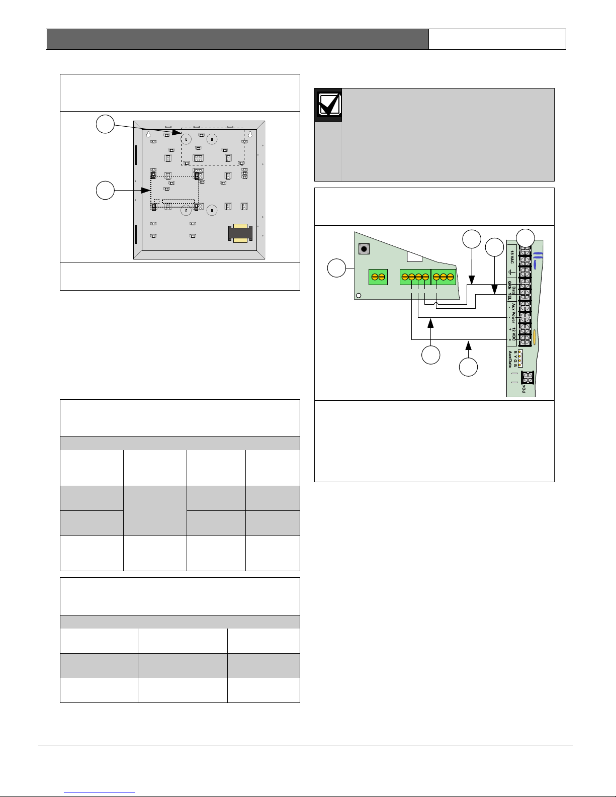
If you need to power the DX2010 with an external
12 VDC power supply, wire it as shown in Figure
30.
1- DX2010 Module
2- Green (G) data wire
3- Yellow (Y) data wire
4- Black (-) wire
5- Red (+) wire
6- External 12 VDC power source
7- Control panel board
Do not tie the black (-) output to
earth ground when using an external
power supply. A ground fault
condition is reported if black (-) is
grounded.
EN | 25
2.6.4 DX2010 Auxiliary Output Wiring
The DX2010 can provide 12 VDC at up to 100 mA
from the Auxiliary Output (-) OUT (+) terminals to
power external devices such as motion detectors.
See Figure 31.
1- DX2010 Module
2- Motion detectors, photo beams, etc.
3- Black (-) wire
4- Red (+) wire
The following maximum wire lengths
apply when wiring the DX2010’s
auxiliary output to remotely powered
devices, such as PIRs and smoke
detectors:
− 15 m (49.2 ft) for 0.8 mm (#22
AWG) wire.
− 30 m (98.4 ft) for 1.2 mm (#18
AWG) wire.
DS7200V2-EXP | Installation Guide | 2. System Installation
and Setup
Bosch Security Systems, Inc. | 04/12 | F01U253045-02
Figure 32: DX2010 Tamper Input Wiring
Figure 33: DX2010 No Tamper
Figure 34: DX2010 Tamper-Wired Zone
Wiring
1R B G Y+OUT-
TMPR COM
1
2
1
2
1
R B
G
Y+OUT-
TMPR
COM
3 4 5 6 7 8COM COM COM
1
2COM
3
1
1
2
2
2.6.5 DX2010 Tamper Input Wiring
Each DX2010 module provides an input for
tamper devices. The tamper input is in addition
to the zone sensor loops. Supervising an
enclosure tamper does not occupy a zone. A fault
on the tamper input is reported as a tamper
event to which the Data Bus address the DX2010
is set.
The tamper input can monitor external NormallyClosed (N/C) tamper switches when wired as
shown in Figure 32. The tamper circuit must be
closed to provide proper Input Expander tamper
supervision to the control panel. Do not use an
EOL resistor.
EN | 26
Use either the tamper input or the on-board
tamper switch. Both cannot be used
simultaneously.
1- DX2010 Module
2- Tamper Jumper
2.6.6 DX2010 Tamper-Wired Zone Wiring
For tamper-wired sensor loop configuration, wire
as shown in Figure 34.
1- DX2010 Module
2- External tamper switch
The DX2014 configuration includes a tamper
spring. Do not use the DX2010 TMPR input in the
DX2014 configuration.
The DX2010’s on-board tamper switch cannot be
used when it is mounted inside the control
panel’s enclosure (wire the tamper input as
shown in Figure 33 if installed in the control
panel’s enclosure).
If neither the tamper input nor the on-board
tamper switch is used, a wire must be placed as
shown in Figure 33.
1- Tamper contact
2- 2.2 k
EOL resistors
3- Alarm contacts (programmable for either
Normally-Open or Normally-Closed)
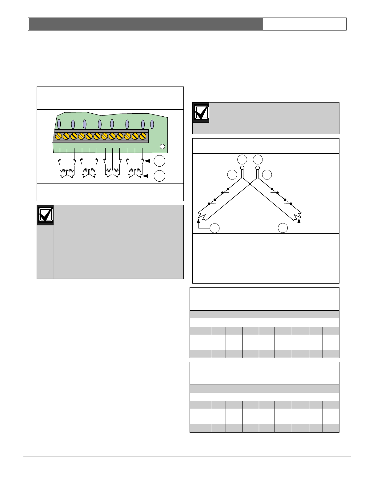
DS7200V2-EXP | Installation Guide | 2. System Installation
and Setup
Bosch Security Systems, Inc. | 04/12 | F01U253045-02
Figure 35: DX2010 Single EOL Zone
Wiring
Figure 36: DX2010 Doubled Zone Wiring
Table 7: Control Panel Locations for DX2010
Address 106
DX2010 Sensor Loop
EOL 1 2 3 4 5 6 7 8
Table 8: Control Panel Locations for DX2010
Address 107 (DS7240V2 only)
DX2010 Sensor Loop
EOL 1 2 3 4 5 6 7 8
1 2 3 4 5 6 7 8COM COM COM C
OM
1
2
2
3
4
1
6
5
2.6.7 DX2010 Single EOL Zone Wiring
The DX2010 supports both Normally-Open and
Normally-Closed contacts in the single EOL zone
configuration.
Use 2.2 k EOL resistors (P/N: 47819) when
wiring as shown in Figure 35.
1- Normally-Closed contacts
2- Normally-Open contacts
The Loop Response Time setting in
the Zone Function Configuration has
no effect on the DX2010. Its response
time is configurable. See “DX2010
Configuration” in the DS7200V2
Expert Programming Guide (P/N:
4998153891).
The DX2010 cannot be used with two-
wire smoke detectors.
EN | 27
2.6.8 DX2010 Doubled Zone Wiring
For the doubled sensor loop configuration, wire
as shown in Figure 36. The loop response time of
doubled sensor loops is fixed at 150 ms. The
control panel can be configured to function with
either Normally-Open or Normally-Closed
contacts. Normally-Closed contacts are
recommended.
Each loop is monitored as a separate
zone.
1- DX2010 Common
2- DX2010 input terminals 1 to 8
3- DX2010 inputs (see Table 7 and Table 8)
4- 2.2 k
EOL resistor
5- 3.65 k EOL resistor
6- DX2010 inputs (see Table 7 and Table 8)
3.65 k 9 10 11 12 13 14 15 16
2.2 k 17 18 19 20 21 22 23 24
3.65 k 25 26 27 28 29 30 31 32
2.2 k 33 34 35 36 37 38 39 40
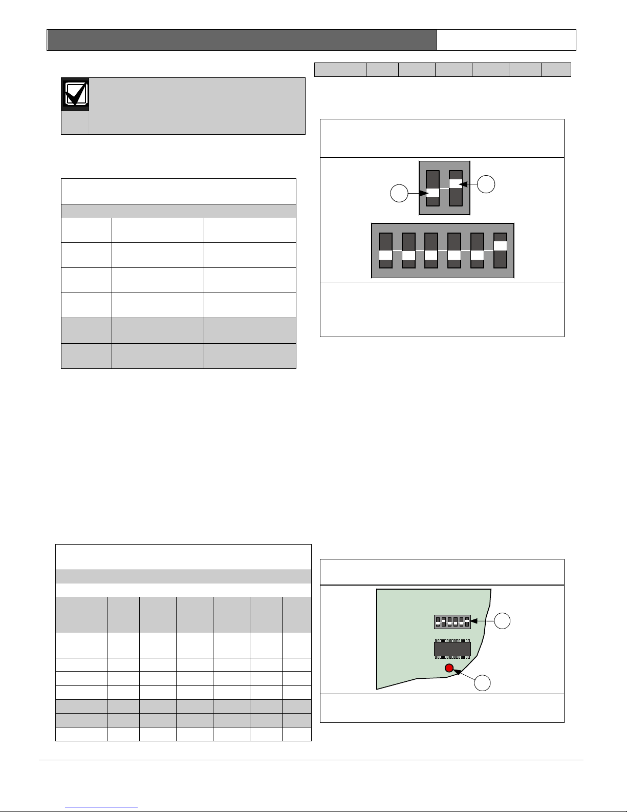
DS7200V2-EXP | Installation Guide | 2. System Installation
and Setup
Bosch Security Systems, Inc. | 04/12 | F01U253045-02
Table 9: DX2010 Address Settings
Location Standard
Sensor Loop*
Doubled
Sensor Loop**
101
Table 10: DX2010 DIP Switch Settings
DX2010 DIP Switch Settings
DIP
Switche
s
S1
S2
S3
S4
S5
S6
Module
Address
32
16 8 4 2 1
ON
ON
ON ON
ON
ON
ON
ON ON
Figure 37: DX2010 DIP Switch
Configuration
Figure 38: DX2010 Status LED Location
ON
1 2 3 4 5 6
1
2
2
2.6.9 DX2010 Addressing
Any time you change the address DIP
switches, cycle the power to the
module OFF and then ON for the
changes to take effect.
Use Table 9 to set the address jumpers for all
DX2010s connected to the control panel.
Shaded rows only apply to the DS7240V2.
EN | 28
107 OFF OFF OFF
See Figure 37 for proper DX2010 DIP switch
configuration.
OFF
1 to 8 Data Bus Addr
9 to 16 Data Bus Addr
102
17 to 24 Data Bus Addr
103
25 to 32 Data Bus Addr
104
33 to 40 Data Bus Addr
105
Data Bus Addr
Data Bus Addr
Data Bus Addr
Data Bus Addr
106
106
107
107
* For Standard Sensor Loop, set the location’s
“Device” parameter to “2.” Set the DX2010
address as shown in Table 10. See Location ##,
Device on page 82 for programming details.
** For Doubled Sensor Loop, set the location’s
“Device” parameter to “3.” Set the DX2010
address as shown in Table 10.
For tamper-wired zones, use Data Bus Addresses
101 to105. Set the device type settings to “2”
(see Location ##, Device on page 82).
Set the address DIP switches as shown in Table
10.
Shaded rows apply only to the DS7240V2.
1- OFF position
2- ON position
Sample address setting shown is for Address
102
2.6.10 DX2010 Status LED
See the following for Status LED operation:
• One flash per second indicates normal
operation.
• LED steady ON can indicate any of the
following:
- Power, no communication.
- “G” wire is not connected or there is a
communication problem between the
control panel and the DX2010.
- No locations (zones) are assigned to the
DX2010 with this address. See Location
##, Zone Function on page 83 for details.
- DX2010 address is not set correctly.
• LED OFF indicates that there is no power to
the module.
101 OFF OFF OFF OFF OFF OFF
102 OFF OFF OFF OFF OFF
103 OFF OFF OFF OFF
104 OFF OFF OFF OFF
105 OFF OFF OFF
106 OFF OFF OFF
OFF
OFF
OFF OFF
1- DX2010 DIP Switches
2- DX2010 Status LED
ON
1 2 3 4 5 6
1
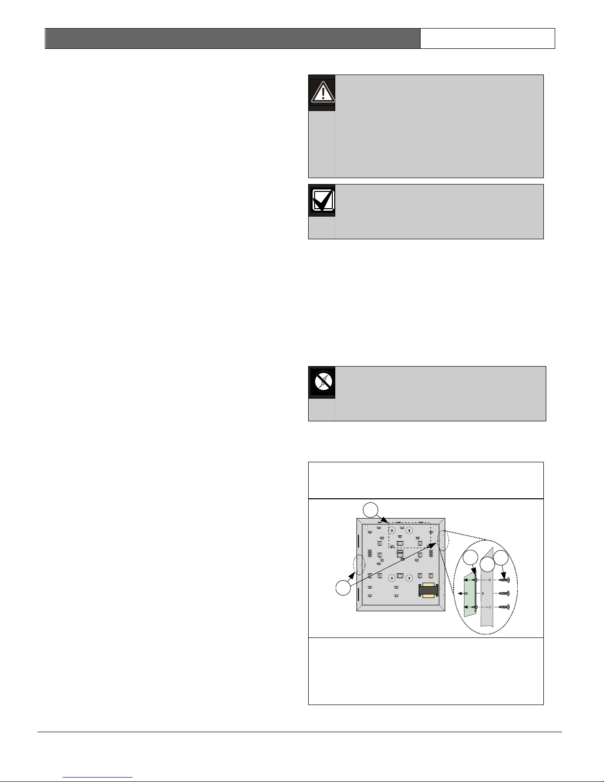
DS7200V2-EXP | Installation Guide | 2. System Installation
and Setup
Bosch Security Systems, Inc. | 04/12 | F01U253045-02
Figure 39: DX3010 to Control Panel
Enclosure Installation
5- Screws (supplied with DX3010)
1
3
4
2
5
2.6.11 DX2010 Supervision
The control panel supervises communication to
the DX2010. If it fails to communicate with the
DX2010, it sends a “DBus Missing” {125} report.
2.7 Off-board Output Setup
(DX3010)
2.7.1 Overview
The DX3010 Octo-Output Expander allows you to
add outputs to your system in groups of eight.
The DS7240V2 supports up to 20 programmable
outputs (4 on-board, 16 off-board using two
DX3010 Output Expanders).
The DS7220V2 supports up to 12 programmable
outputs (4 on-board, 8 off-board using one
DX3010 Output Expander).
The DX3020 X-10 Interface Module allows the
control panel to control up to 16 X-10 modules.
The DX3020 emulates up to 2 DX3010 modules.
You can assign any of the programmable output
functions to the DX3010’s individual outputs
separately. See Output Parameters on page 86 for
programming details.
Current Draw: 10 mA Standby plus 40 mA for
each energized output (relay) for a total of 330
mA maximum with all eight outputs energized.
See the DX3010 Installation Guide (P/N: 49529)
for complete installation, addressing and
operating instructions.
EN | 29
2.7.2 DX3010 Relay Outputs
Outputs can activate when setting the
DX3010’s address DIP switches,
programming the control panel,
resetting the control panel or applying
power to the control panel.
Disconnect equipment connected to
outputs when performing these
functions.
The DX3010 relay outputs are not
supervised and cannot be used in fire
or combined fire/burglary installations
for primary indicating devices.
Each DX3010 output provides a Form “C” dry
contact rated for 5.0 A at 28 VDC. NormallyOpen, Common, and Normally-Closed terminals
are available for each relay output. When an
individual output is activated, there is continuity
between the Normally-Open and Common
terminals. When the output is not activated, there
is continuity between the Normally-Closed and
Common terminals.
2.7.3 DX3010 Installation
The DX3010 contains static-sensitive
components. Follow anti-static
procedures when handling this
module.
You can install the DX3010 in the control panel’s
enclosure with the hardware supplied with the
DX3010. See Figure 39.
1- Control panel board location
2- DX3010 installation locations
3- DX3010 terminal block
4- Enclosure wall
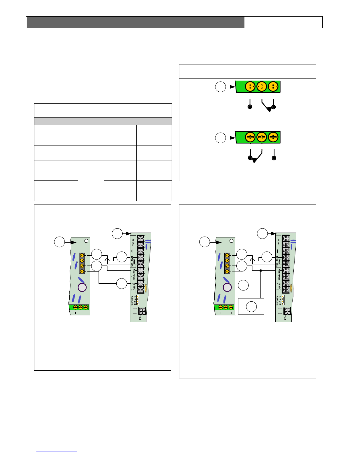
DS7200V2-EXP | Installation Guide | 2. System Installation
and Setup
Bosch Security Systems, Inc. | 04/12 | F01U253045-02
Table 11: DX3010 Wire Lengths
Power
Source
0.8 mm
(#22
AWG)
1.2 mm
(#18 AWG)
Figure 40: DX3010 to Control Panel
Wiring
Figure 41: DX3010 Output States
Figure 42: DX3010 to Control Panel
Wiring (External Power Supply)
BATT+
BATT-
NC NOC
8
Y
B
R
G
3
5
4
6
2
1
BATT+
BATT-
NC NOC
8
Y
B
G
3
5
4
2
1
+ -
7
6
R
Distance from the control panel is determined by
the total combined wire length of all devices
(including keypads) connected to the control
panel’s Data Bus terminals. The combined wire
length must not exceed 305 m (1007.7 ft) using
0.8 mm (#22 AWG) wire.
2.7.4 DX3010 Wiring
See Table 11 for Data Bus wire length
requirements.
Control Panel
to DX3010
Control Panel
to DX3010
External Power
Supply to
DX3010
Control
Panel
Externa
l Power
Supply
12.2 m
(40 ft)
305 m
(1007.7
ft)
12.2 m
(40 ft)
24.4 m
(80 ft)
610 m
(2001 ft)
24.4 m
(80 ft)
EN | 30
You can use either one of the Aux Power (-)
terminals and either one of the 12 VDC (+)
terminals when connecting devices to the control
panel.
1
NC
NO
C
2
NC
1- Output activated state
2- Output deactivated state
If you need to power the DX3010 from an
external power supply, connect it to the power
supply and the control panel.
NO
C
1- DX3010 Module
2- Control panel board
3- Yellow (Y) data wire
4- Green (G) data wire
5- Black (-) wire
6- Red (+) wire
1- DX3010 Module
2- Control panel board
3- Yellow (Y) data wire
4- Green (G) data wire
5- Black (-) wire
6- Red (+) wire
7- External 12 VDC power supply
 Loading...