

Bosch DS6R2 Installation And Operation Manual
DS6R2
Installation and Operation Guide
Self-Contained Control
EN
Panel

DS6R2 | Installation and Operation Guide | Trademarks
Trademarks
Microsoft® is a registered trademark of Microsoft
Corporation in the United States and/or other
countries.
2 Bosch Security Systems, Inc. | 4/08 | F01U081960-01

DS6R2 | Installation and Operation Guide | Contents
.
Contents
1.0 Overview.............................................................................................................................................................4
1.1 Multi-Tenant System (MTS) Overview .............................................................................................................4
1.2 MTS Device Address...........................................................................................................................................4
1.3 DS6R2 Overview ................................................................................................................................................. 4
2.0 Installation........................................................................................................................................................... 6
2.1 Mounting the DS6R2........................................................................................................................................... 6
2.2 Wiring the DS6R2................................................................................................................................................ 6
2.2.1. System Wiring ...............................................................................................................................................6
2.2.2. Input Wiring .................................................................................................................................................. 7
2.2.3. Output Wiring ............................................................................................................................................... 8
2.2.4. Wireless Receiver..........................................................................................................................................8
3.0 Programming......................................................................................................................................................9
3.1 Entering Programming Mode.............................................................................................................................9
3.2 Changing Programming Values ......................................................................................................................... 9
3.3 Exiting Programming Mode ...............................................................................................................................9
3.4 Programming Wireless Devices........................................................................................................................ 14
3.5 Resetting Default Values ................................................................................................................................... 14
3.5.1. Reset the Master Code ...............................................................................................................................14
3.5.2. Reset Programming Default Values..........................................................................................................14
4.0 Wireless Maintenance ....................................................................................................................................15
4.1 Wireless Device Test Mode ..............................................................................................................................15
4.2 Low Battery Trouble.......................................................................................................................................... 15
4.3 Supervisory Trouble ..........................................................................................................................................15
5.0 Specifications....................................................................................................................................................15
6.0 RS-485 Bus Address .........................................................................................................................................16
Bosch Security Systems, Inc. | 4/08 | F01U081960-01 3

DS6R2 | Installation and Operation Guide | 1.0 Overview
1.0 Overview
1.1 Multi-Tenant System (MTS) Overview
MTS is a distributed security system for monitoring
and controlling a large number of small sites.
Examples include apartment and condominium
complexes, retail plazas, office buildings, and
educational and hospital campuses.
A typical MTS installation consists of the following
components:
• MTSW Security Station Software: MTSW is a
Microsoft
a PC and monitored by guard station personnel.
• MTR Communication Receiver: The MTR
receives and handles alarm events from devices
connected to the CAN RS-485 bus. It monitors
and reports CAN bus status and other system
internal events, and interfaces with MTSW to
synchronize system data.
• MTGW CAN RS-485 Bus Gateway: The MTGW
converts data back and forth from an RS-485
format to a Controller Area Network (CAN) bus
format. The system supports up to 100 MTGWs
per CAN bus line. The MTGW provides three RS485 loops that support a total of 120 RS-485
devices spread across the three loops.
• RS-485 Bus Devices: Refer to Table 1 for a list of
supported RS-485 devices.
Table 1: MTS RS-485 Bus Devices
RS-485 Device Description
DS6R2 6-zone self-contained control panel
DS12R 12-zone self-contained control panel
MT1-1 Single-zone input device
MT1-2 Two-zone input device
MT1-8 8-zone input device
MT2-8 8-output device
MT3-1 Single-zone input/output device
®
Windows-based application installed on
CAN bus wiring requirements are as follows:
• CAN Bus Interface: Connect the CAN bus to the
MTR Communication Receiver with at least
1.5 mm (16 AWG) shielded twisted-pair wire;
maximum length: 2000 m (6500 ft).
• RS-485 Buses 1-3: Use at least 1.0 mm (20 AWG)
shielded twisted-pair wire for the RS-485 bus;
maximum length: 1200 m (3900 ft). RS-485 bus
wiring status is supervised.
1.2 MTS Device Address
You must assign an address to each device in the
system. The address consists of at least four segments.
For example:
1.2.5.3.6
• 1: This segment identifies the number assigned to
the MTR central receiver (01 to 99).
• 2: This segment identifies the CAN bus number
occupied by the MTGW (1 or 2).
• 5 : This segment identifies the MTGW’s CAN bus
address (1 to 100).
• 3 : This segment identifies the device’s RS-485
address (1 to 120).
• 6 : This segment identifies the zone number of an
input or output device connected to the RS-485
device.
To set the address on this device, refer to Section 6.0
RS-485 Bus Address on page 16.
1.3 DS6R2 Overview
The DS6R2 is a self-contained, six-zone control panel.
Use it as a stand-alone security system, or connect it to
a Multi-tenant System (MTS). MTS combines
individual apartment housing units into a single
monitoring system.
The DS6R2 supports:
• 6 alarm input zones
• 1 alarm relay output
• 2 solid-state outputs
• 1 keyswitch input
• 1 master code
• 3 user PIN codes
• 1 duress code
• 1 door unlock code
• RF3212 and RF3212E Wireless Receiver
• RF3332 and RF3334 Key Fobs
• RF3332E and RF3334E Key Fobs
4 Bosch Security Systems, Inc. | 4/08 | F01U081960-01
.
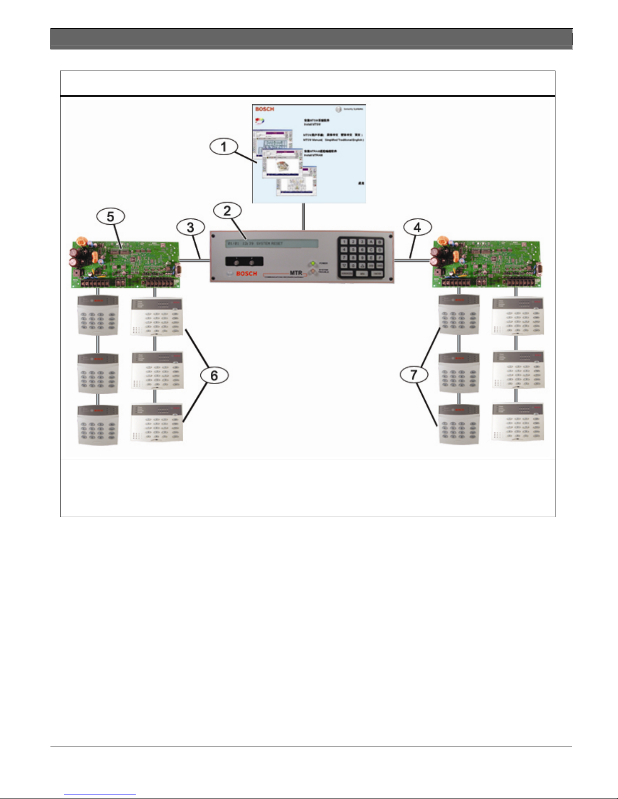
Figure 1: MTS System Overview
DS6R2 | Installation and Operation Guide | 1.0 Overview
1- MTSW Security Station Software
2- MTR Communication Receiver
3- CAN Bus 1
4- CAN Bus 2
5- MTGW CAN RS-485 Bus Gateway
6- RS-485 Device (DS12R pictured)
7- RS-485 Device (DS6R2 pictured)
Bosch Security Systems, Inc. | 4/08 | F01U081960-01 5
DS6R2 | Installation and Operation Guide | 2.0 Installation
2.0 Installation
Install the DS6R2 as described in this
document to avoid damage to the devices.
When installation is complete, perform a
2.1 Mounting the DS6R2
You can mount the DS6R2 directly to the intended
surface (flush or semi-flush), or you can mount it to an
electrical box.
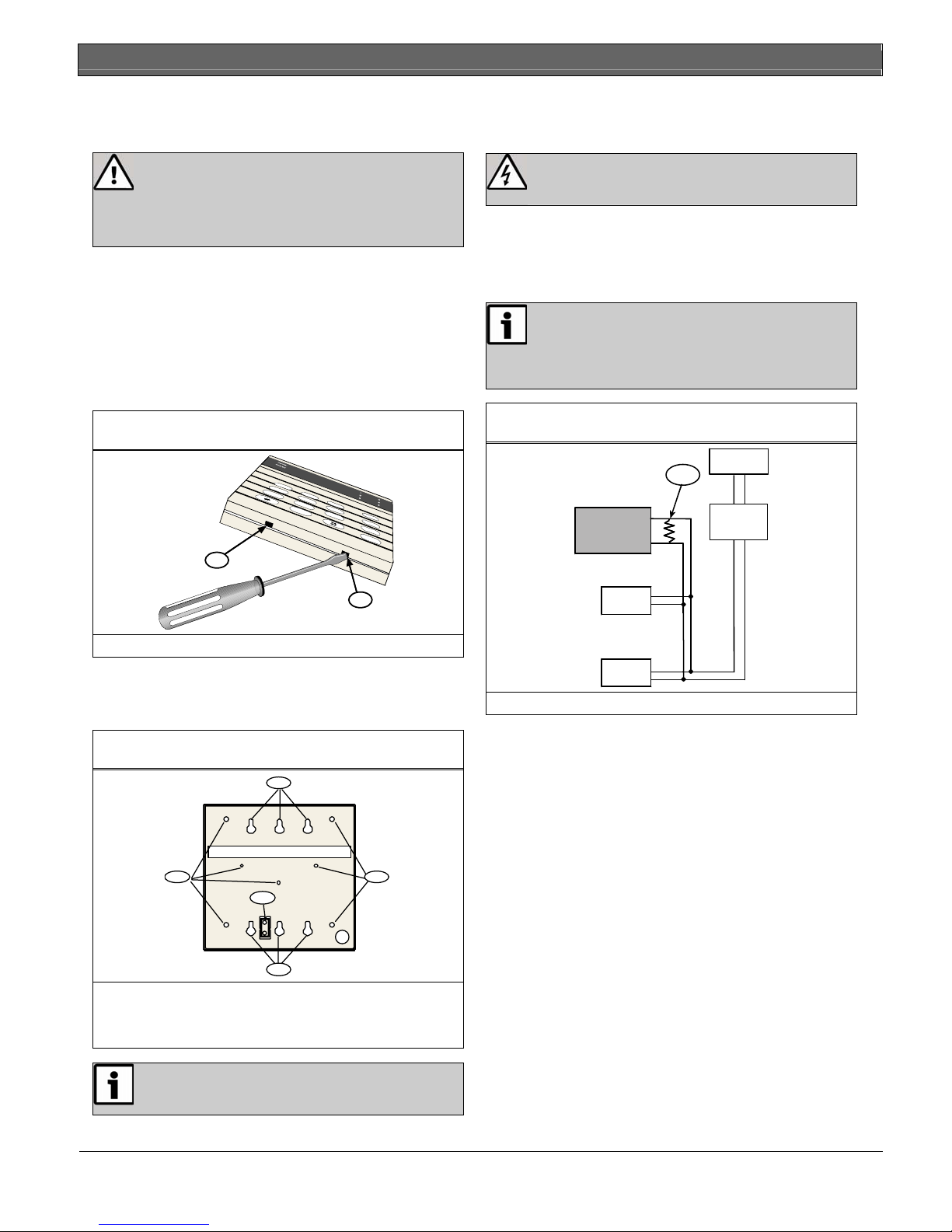
1. To open the keypad, use a screwdriver to press the
Figure 2: Opening the DS6R2
full system test.
release tabs on the bottom of the keypad.
Refer to Figure 2.
2.2 Wiring the DS6R2
2.2.1. System Wiring
Remove power to all devices before
connecting or removing the DS6R2.
Connect devices as shown in Figure 4. If the DS6R2 is
the last device on the RS-485 bus, connect a 120 Ω
EOL resistor in parallel with the
RS-485 bus.
Only the last device on the RS-485 bus
requires a 120 Ω EOL resistor (included
with the MTGW CAN-RS-485 BUS
Figure 4: RS-485 Bus Wiring
Gateway).
MTGW
1
1
1
1- Release tab
2. Mount the base on the intended surface or
electrical box.
Refer to Figure 3.
Figure 3: Mounting Holes
2
1 1
3
DS6R
MT1-8
MT1-1
1- 120 Ω EOL resistor
RS-485
1
2
1- Holes for surface-mounting
2- Holes for electrical box
3- Hole for wall tamper screw
To use the wall tamper feature, mount the
DS6R2 directly to the intended surface.
6 Bosch Security Systems, Inc. | 4/08 | F01U081960-01
 Loading...