

Bosch DS435I Installation Manual
INSTALLATION INSTRUCTIONS
Receiver
Transmitter
DS435i Photoelectric Intrusion
Detection System
1.0 General Information
Description
The DS435i is a pulsed active infrared photoelectric intrusion
detection system designed to provide an alarm activation upon
the detection of an intruder passing through its beam. It consists
of a separate Transmitter and Receiver and is capable of
coverage ranges up to 500 ft. (150 m).
The Transmitter emits an invisible, pulsed infrared beam
which is received by the Receiver. If an intruder passes
between the Transmitter and Receiver, causing a beam
blockage for a minimum of 55 ms, the Receiver will indicate an
alarm.
Additionally, the system includes a reference wire which
synchronizes the Receiver with the Transmitter and prohibits
the Receiver from setting up on other sources. The Receiver
has an alarm memor y feature which is controlled by switched
voltage. The DS435i receiver and transmitter are intended to
be mounted indoors only.
2.0 Mounting
• Choose a location where an intruder entering the area will have
to cross between the Transmitter and the Receiver .
• Mounting surface should be rigid, and selected as to offer a
clear line of sight between the Transmitter and Receiver .
• Remove the cover of the Transmitter and, using the back of the
chassis as a template, locate and mark the four keyed mounting
slots on the mounting surface.
• Prestart the mounting screws in the mounting surface, attach
and secure the chassis to the mounting surface.
• Repeat the mounting procedure using the Receiver.
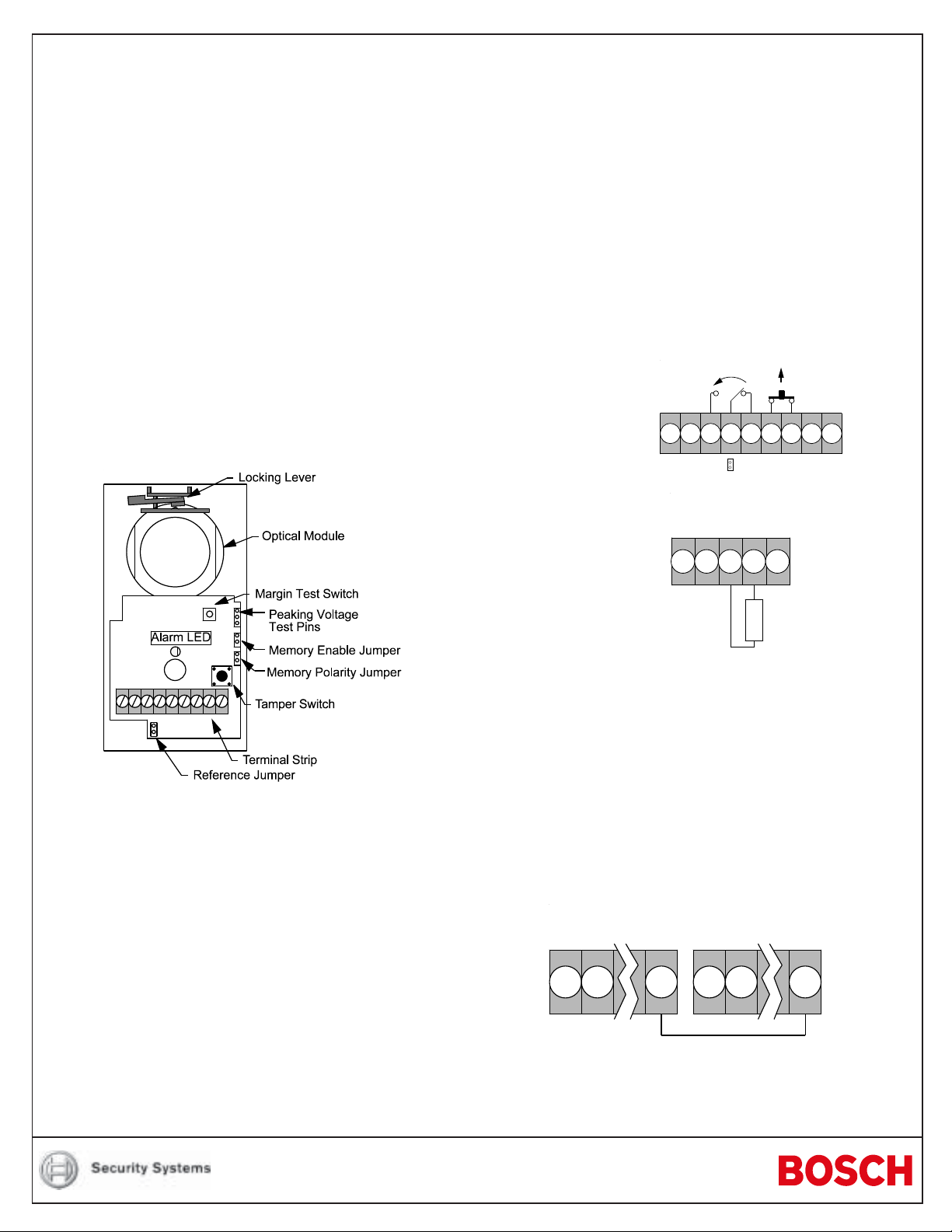
3.0 Wiring
Wire the Transmitter and Receiver as shown.
Tamper
Reference
Reference Jumper
Memory
Receiver Wiring
Input Power
8 - 14.5 VDC
-
12345678 9
Alarm
+
Specifications
Input Power: 8 to 14.5 VDC.
Connect the unit only to a UL Listed power supply or control unit
capable of providing at least 4 hours of standby time.
Current Draw: Transmitter - 8 mA @ 12 VDC.
Receiver - 20 mA @ 12 VDC.
Range: 500 ft. (150 m).
Alarm Output: Form "C" Rated at 0.125 mA @ 28 VDC.
Tamper Output: Form "A" Rated at 0.125 mA @ 28 VDC.
Temperature: Storage and operating temperature range is
0°F to +120°F (-18°C to + 49°C).
installations the operating range is +32°F
+120°F (0°C to +49°C).
Optional
Accessories: AL402 Alignment Light, TC6000 Test Cord,
AE405 Splash Resistant Enclosure, M402A
Mirror. The AE405 and M402A shall not be
used in UL Certificated installations.
For UL
Transmitter Wiring
Input Power
8 - 14.5 VDC
Retransmit
-+
1234
Circuit
Reference
5
E
1 KΩ End of Line
O
Resistor
L
Reference Wire:
The Receiver is synchronized with the Transmitter by use of a
reference wire. This prevents the Receiver from being set- up by
another source such as another Transmitter.
• Remove the reference jumper located below the terminal strip.
• Connect a reference wire between terminal 8 of the Receiver
and terminal 5 of the Transmitter.
• If the Transmitter and Receiver are not powered from the same
power supply , connect terminal 1 (–) of the Transmitter to terminal
1 (–) of the Receiver .
-+
12 8
Reference
-+
12
NOTE: If a reference wire is not used, the reference jumper must
be in place.
Reference
5
Alarm Retransmission Circuit Information:
The Transmitter allows connection of normally open or normally
closed contacts to a supervised alarm retransmission circuit.
Alarm retransmission allows dry contact devices such as door or
window contacts to be wired into the Transmitter using it as a
relay path to the Receiver without additional wiring to the Control
Panel.
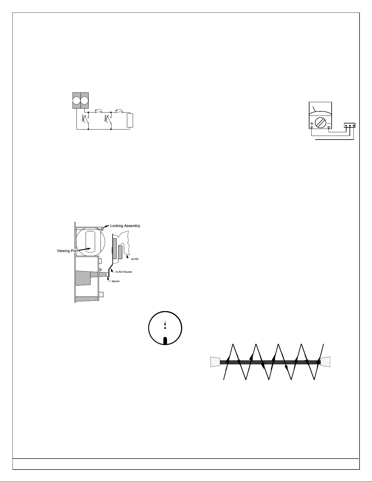
• Adjust the AL402 until the flashing light falls directly on the
Receiver.
• At the Receiver, unlock the optical module by swinging the
locking lev er forward. Align the optical module until the flashing
light from the AL402 falls completely through the hole in the
white image plane.
Retransmission Wiring:
Transmitter T er minals
34
Alarm Alarm
N/CN/C
E
1 KΩ EOL
N/O
O
N/O
L
Resistor
4.0 Alignment
NOTE: The use of an AL402 Alignment Light is suggested in the
alignment of this detector.
Transmitter Alignment:
• Mount the AL402 Alignment Light to the Receiver and connect
the two AL402 leads to the spade lugs on the receiver power
terminals (1 and 2).
• Adjust the AL402 until the flashing light falls directly on the
Transmitter. Lock the AL402 into place.
• Remove the AL402 from the Transmitter.
Fine Peak Alignment:
• Fine peak the Receiver alignment by
connecting a VOM on its lowest DC voltage
scale to the Peaking Voltage Tests points
on the Receiver using a TC6000 Test Cord.
• Adjust the Receiver's optical module until
TC6000
WHITE
RED
BLACK
the highest voltage is shown on the meter .
• Lock the optical module in place and remove the meter .
• Insert the module seals if desired.
Margin Test Switch:
The Margin Test Switch on the Receiver helps insure that the
detector is aligned properly by decreasing the signal into the
Receiver when pressed.
• Press and hold the Margin Test Switch. Be careful not to block
the beam when pressing the switch.
• At the transmitter , unloc k the optical module by
swinging the locking lever forward. Look through
Align Light
Through Hole
the viewing port on the side of the optical module
and align the optical module until the flashing
light from the AL402 falls completely through the
hole in the white image plane.
Image Plane
• Lock the optical module in place by returning the locking lever
to its original position.
• Insert the module seal if extra bug and dust immunity is desired.
Receiver Alignment:
• Remove the AL402 from the Receiver and mount it on the
Transmitter. Connect the two AL402 leads to the Transmitter
power terminals (1 and 2).
The Alarm LED should remain OFF while pressing the Margin
T est Switch. If the LED goes ON, the alignment is insufficient and
the detector should be realigned.
5.0 Setup And Walk Testing
• Place the covers on both units.
• Walk test the system by passing between the Transmitter and
Receiver at several points in the coverage area. Take care to
ensure that the beam is parallel to the floor and not reflecting
off of polished floors or walls.
NOTE:
The infrared beam may be reflected off of shiny objects,
walls, or floors. It is extremely important to walk test the
system at all points that coverage is expected.
Page 2 © 2004 Bosch Security Systems DS435i Installation Instructions
 Loading...