

Bosch DS415i Installation Instructions Manual
Installation Instructions
DS415i Photoelectric Intrusion
Detection System
1.0 General Information
Description:
The DS415i is a pulsed active infrared photoelectric intrusion detection
system designed to provide an alarm activation upon the detection of
an intruder passing through its beam. It consists of a separate
Transmitter and Receiver and is capable of coverage ranges up to
500 ft. (150 m). The Transmitter emits an invisible, pulsed infrared
beam which is received by the Receiver. If an intruder passes between
the Transmitter and Receiver, causing a beam blockage for a minimum
of 55 ms, the Receiver will indicate an alarm. The DS415i receiver
and transmitter are intended to be mounted indoors only.
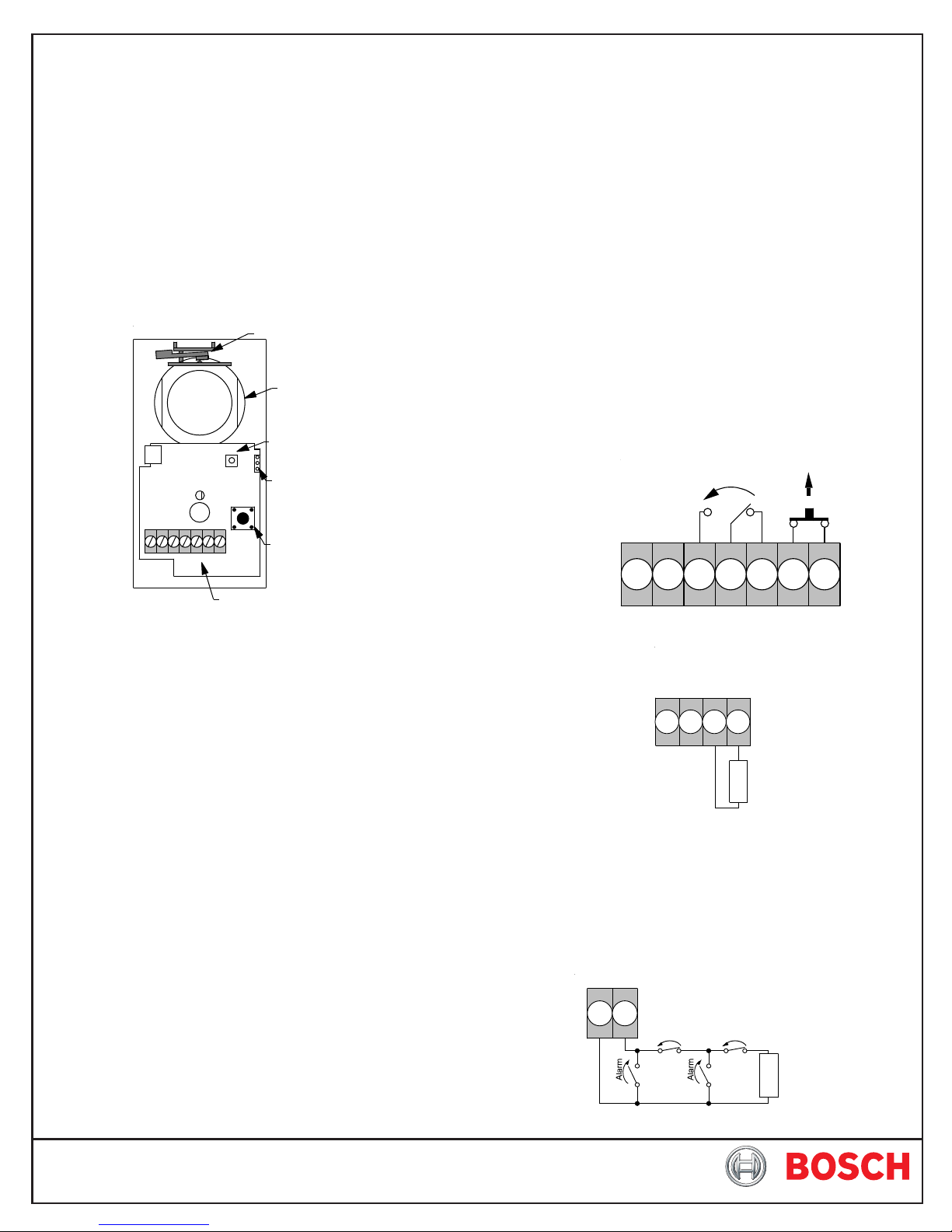
Locking Lever
Optical Module
Battery
Pins
Alarm LED
Margin Test Switch
Peaking Voltage
Test Pins
• Optional Accessories: TR12 Transformer, AL402
Alignment light, P333 Standby
Battery, C6000 Test Cord,
AE405 splash Resistant
Enclosure, M402A Mirror.
The AE405 and M402A shall not be used in UL Certificated
Installations.
2.0 Mounting
• Choose a location where an intruder entering the area will have to
cross between the Transmitter and the Receiver.
• Mounting surface should be rigid, and selected as to offer a clear
line of sight between the Transmitter and Receiver.
• Remove the cover of the Transmitter and, using the back of the
chassis as a template, locate and mark the four keyed mounting
slots on the mounting surface.
• Prestart the mounting screws in the mounting surface, attach and
secure the chassis to the mounting surface.
• Repeat the mounting procedure using the Receiver.
3.0 Wiring
Wire the Transmitter and Receiver as shown.
•
Receiver Wiring
Input Power
8 - 15 VDC
or 12 VAC
Alarm
Tamper
Tamper Switch
Terminal Strip
Specifications:
• Input Power: 8 to 14.5 VDC or 12 VAC.
NOTE: For DC input applications connect the unit only to a UL Listed
power supply or control unit capable of providing at least 4 hours
of standby time. For UL certificated, AC input applications the
TR12 transformer and P333 battery pack shall be used.
The model DS415iDC detectors are identical to the model
DS415i except the DS415iDC is intended to be connected to
a 12 VDC power source. The power source should only be a
UL Listed power supply or control unit within the range of 8 to
14.5 VDC.
Since the DS415iDC does not contain an internal standby
battery, the power source should be capable of providing at
least 4 hours of standby time in the event primary power is lost.
• Current Draw: Transmitter - 8 mA @ 12 VDC.
68 mA RMS with battery.
Receiver - 33 mA @ 12 VDC.
95 mA RMS with battery
• Range: 500 ft. (150 m).
• Alarm Output: Form "C" Rated at 125 mA @ 28 VDC.
• Tamper Output: Normally Closed Rated at 125 mA @
28 VDC.
• Temperature: Storage and operating temperature range
is 0°F to +120°F (–18°C to +49°C). For UL
installations the operating range is +32°F
to +120°F (0°C to +49°C), indoor use.
-+
1234567
Transmitter Wiring
Alarm Retransmission Circuit Information:
The Transmitter allows connection of normally open or normally
closed contacts to a supervised alarm retransmiss circuit. Alarm
retransmission allows dry contact devices such as door or window
contacts to be wired into the Transmitter using it as a relay path to
the Receiver without additional wiring to the Control Panel.
Retransmission Wiring:
Trans mitte r Termina ls
34
Input Power
8 - 15 VDC
or 12 VAC
-+
1234
Alarm Alarm
N/O
Retransmission
Circuit
E
O
L
N/CN/C
N/O
1 KΩ End of Line
Resistor
E
1 KΩ EOL
O
Resistor
L
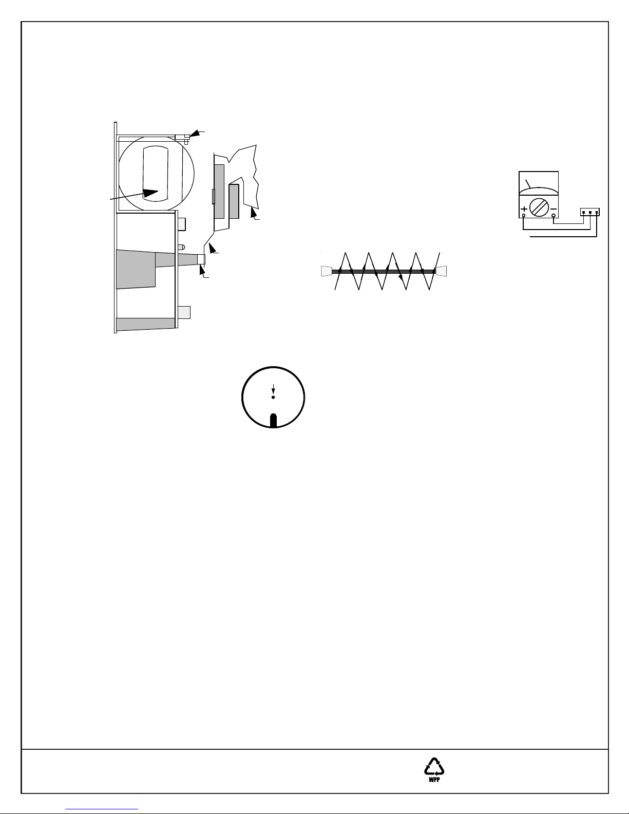
4.0 Alignment
NOTE: The use of an AL402 Alignment Light is suggested in the
alignment of this detector.
Transmitter Alignment:
• Mount the AL402 Alignment Light to the Receiver and connect the
two AL402 leads to the spade lugs on the receiver power
terminals (1 and 2).
Locking Assembly
Viewing Port
AL402
AL402 Bracket
Spacer
• Adjust the AL402 until the flashing light falls directly on the
Transmitter. Lock the AL402 into place.
• At the Transmitter, unlock the optical module
by swinging the locking lever forward. Look
through the viewing port on the side of the
optical module and align the optical module
until the flashing light from the AL402 falls
completely through the hole in the white image
plane.
• Lock the optical module in place by returning the locking lever to
its original position.
• Insert the module seal if extra bug and dust immunity is desired.
Receiver Alignment:
• Remove the AL402 from the Receiver and mount it on the
Transmitter. Connect the two AL402 leads to the Transmitter
power terminals (1 and 2).
• Adjust the AL402 until the flashing light falls directly on the
Receiver.
• At the Receiver, unlock the optical module by swinging the locking
lever forward. Align the optical module until the flashing light
from the AL402 falls completely through the hole in the white
image plane.
• Remove the AL402 from the Transmitter.
Fine Peak Alignment:
• Fine peak the Receiver alignment by connecting a VOM on its
lowest DC voltage scale to the Peaking Voltage Tests points on
the Receiver using a TC6000 Test Cord.
• Adjust the Receiver's optical module until the highest voltage is
shown on the meter.
• Lock the optical module in place and remove the meter.
• Insert the module seals if desired.
Align Light
Through Hole
Image Plane
Margin Test Switch:
The Margin Test Switch on the Receiver helps ensure that the detector is aligned properly by decreasing the signal into the Receiver
when pressed.
• Press and hold the Margin Test Switch. Be careful not to block
the beam when pressing the switch.
• The Alarm LED should remain OFF while pressing the Margin
Test Switch. If the LED goes ON, the alignment is insufficient and
the detector should be realigned.
5.0 Setup And Walk Testing
• Place the covers on both units.
• Walk test the system by passing between
the Transmitter and Receiver at several
points in the coverage area. Take care to
ensure that the beam is parallel to the floor
and not reflecting off of polished floors or
walls.
TC6000
WHITE
RED
BLACK
NOTE: The infrared beam may be reflected off of shiny objects,
walls, or floors. It is extremely important to walk test the
system at all points that coverage is expected.
6.0 Battery Connection/Testing
NOTE: The battery is for AC Units Only. Do not install the battery on
DC powered units.
• The P333 Battery is supplied as backup power when the unit will
be powered from a transformer.
• Plug the battery connector into the battery pins on the unit.
• Unplug the AC Transformer at the Transmitter and observe the
Receiver's Alarm LED.
he Receiver's Alarm LED should remain OFF
T
• Walk test the units by walking between the Transmitter and
Receiver. Insure that the Receiver's alarm LED lights when the
beam is blocked.
• Unplug the Receiver's Transformer and repeat the walk test.
• Plug both Transformers back in.
7.0 Alarm Retransmission Circuit Testing
If the retransmission circuit is used, Activate the devices connected
to the retransmission circuit and observe the Receiver's alarm
LED.
NOTE: The Receiver's alarm LED should light and the alarm relay
should transfer when devices connected to the
retransmission circuit are activated.
8.0 Other Information
Maintenance:
At least once per year, the front covers of both units should be
cleaned using a commonly available window cleaner, and a soft,
dry cloth.
Testing:
The end user should be instructed on the proper test procedures
and frequency.
The only way to insure continued daily operation of any intrusion
detection system is to perform regular walk tests of the coverage
area.
© 2008 Bosch Security Systems, Inc.
130 Perinton Parkway, Fairport, New York, USA 14450-9199
(800) 289-0096
08/08
DS415i Installation Instructions
P/N: F01U068107-07 Page 2
 Loading...