

Bosch DS306E Installation Instructions Manual
Other Information
Perform maintenance annually. Check the
range and coverage according to the
Setup
and Walk Testing
instructions.
Ensure continual daily operation by instructing the end user to daily walk through the
outer edge of the coverage pattern. This assures an alarm output before arming.
Mirror Information
The mirror is adjustable from +2° to -18°
vertically and from +10° to -10° horizontally.
Change the mirror by pulling it out from its
resting grooves.
Installation Instructions
for the
DS306E ASIC Based
Passive Infrared
Intrusion Detector
Specifications
• Input Power: 6 VDC to 15 VDC; 15 mA
at 12 VDC
• Standby Power: There is no internal
standby battery. Connect to DC power
sources that can supply standby power if
the primary power fails. For each hour of
standby time that is needed, 15 mAh is
required.
• Coverage:
Broad (standard): 15 m by 15 m
(50 ft by 50 ft)
Barrier
*: 25 m by 5 m (80 ft by 16 ft)
Long Range
*: 40 m by 3 m
(120 ft by 10 ft)
*
Barrier and Long Range mirrors are
available as options.
• Sensitivity: Adjustable for Standard,
Intermediate, or High.
• Alarm Relay: Normally closed reed relay
with contacts that are rated at 28 VDC,
125 mA maximum for DC resistive loads.
• Tamper Switch: Normally closed (with
cover in place) tamper switch. Contacts
area rated at 28 VDC, 125 mA maximum.
• Temperature: The storage and operating
range is -20°F to +120°F (-29°C to +49°C).
• Options: B328 Gimbal Mount Bracket,
B333 Swivel Bracket, TC6000 Test
Cord, OMB77-3 Barrier Mirror, and
OMLR77-3 Long Range Mirror.
• U.S. Patent Numbers: 4,764,755 and
5,083,106
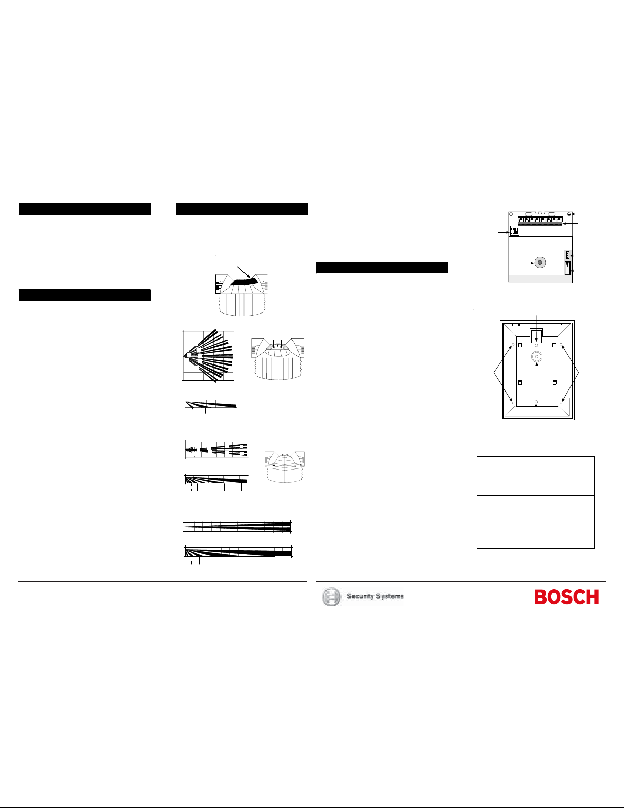
Coverage Patterns
This product is factory assembled with the
look down zones (O, P, and Q) masked out. If
you want to use these zones, remove the
masking tape from the lens.
Remove the mask by
peeling back the tab.
ABCDEFGH I
J
KLM
N
F
e
e
t
Side View
0
Meters
F
e
e
t
0
10
40
120
E
DC B
A
0 Feet
Top View
Long Range Coverage (OMLR77)
0
Meters
0Feet
0
5
5
40
120
M
e
t
e
r
s
0
1.5
1.5
0
3
M
e
t
e
r
s
Mirror adjusted to -1°
0
Meters
0
Feet
50
15
0
F
e
e
t
25
25
Top View
Broad Coverag
e
7.5
7.5
M
e
t
e
r
s
0
A
B
C
D
E
F
G
H
I
J
K
L
M
N
O
P
Q
015
50
Meters
5
0
10
F
e
e
t
Side View
O-Q
0
Feet
J-N A-I
M
e
t
e
r
s
0
3
Mirror adjusted to -5°
Mirror Segment
to Pattern Reference
View of Front
Polished Surface
A
B
C
D
EF
G
H
IJ
KL
+2
0
-8
-16
+2
0
-8
-16
Top View
Barrier Coverage (OMB77)
0
Meters
0
Feet
25
80
F
e
e
t
10
10
0
M
e
t
e
r
s
3
3
0
B
C
D
EFG
H
I
JKL
A
Side View
0
Meters
0
5
0
10
F
e
e
t
25
80
Feet
K-L I-J
G-H E-F
C-D
A-B
0
3
M
e
t
e
r
s
Mirror adjusted to -2°
Mirror Segment
to Pattern Reference
View of Front
Polished Surface
ABCDEFGHI
J
K
L
M
N
OPQ
+2
0
-8
-16
+2
0
-8
-16
OFF
123
Tam pe r
Switch
Noise
Voltage
LED
Configuration
Switches
T-Strip
Chassis
Screw
Circuit Board Components
Corner
Mounting
Hole
Corner
Mounting
Hole
Surface Mounting Hole
Surface Mounting Hole
Bracket
Mounting Hole
Detector Enclosure
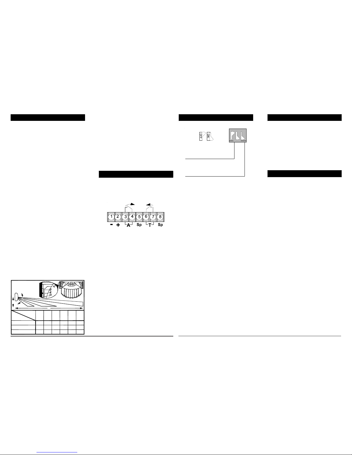
Avoid
Direct Hot and Cold Drafts, Windows,
Small Animals, Air Conditioner Outlets,
Heat Sources, Direct Sunlight
Remember
Does not detect through glass.
Best catch performance is across
the pattern.
When using two or more detectors,
cross patterns for best coverage.
© 2004 Bosch Security Systems
130 Perinton Parkway , F airport, New York, USA 14450-9199
Customer Service: (800) 289-0096; Technical Support: (888) 886-6189
03/04
DS306E Installation Instructions
P/N: 28831F Page 4
Mounting
• Select a location that is most likely to
intercept an intruder moving across the
coverage pattern. The recommended
mounting height is 2.3 m (7.5 ft).
Note: Ensure the mounting surface is solid
and vibration free.
• Remove the cover. Insert a thin screwdriver
into the notch at the bottom of the cover
and pry up.
• Remove the circuit board/mirror unit from
the enclosure. Push the board/mirror unit
toward the top of the enclosure until it
clears its four retainer tabs, and lift out.
• Open the knockout wire entrance and
route the wiring through.
Surface or Corner Mounting
• Open two holes for surface or corner
mounting.
• Using the enclosure as a template, prestart the mounting screws.
• Firmly mount the detector.
• Replace the circuit board/mirror unit.
Mirror Alignment
Note: Touching the mirror surfaces can
lead to performance degradation.
For the best performance, the mirror must
be adjusted vertically for the maximum desired detection range (distance) and mounting height. The angle adjustment markings
are located on both sides of the mirror as
shown in the following chart.
X
Y
MIRROR
ANGLE
ADJUSTMENT
2.0 (6.5)
2.3 (7.5)
2.6 (8.5)
-15° -8° -7° -6° -5°
-16° -12° -10° -8° -7° -6°
-8°-9°-10°-12°-15°-17°
5
(16)7(23)9(30)11(36)13(43)15(50)
Y m(ft)
X m(ft)
-10°
Page 2 © 2004 Bosch Security Systems DS306E Installation Instructions
DS306E Installation Instructions © 2004 Bosch Security Systems Page 3
• Adjust by sliding the mirror forward or
backward until the angle adjustment
markings are in line with the markers on
each side of the frame.
• Use the chart to identify the correct vertical
angle based on mounting height (X),
mirror type, and maximum range (Y).
• Adjust the mirror horizontally by rotating
(aiming) it from side to side.
• Walk test the unit as described in
Setup
and Walk Testin
g.
Wiring
CAUTION: Only apply power after the
connections are made and
inspected.
Connect wiring as shown below.
Terminal Descriptions
• 1 (-) and 2 (+): Input Power . Use wire that
is no smaller than #22 AWG wire pair
(150 m [500 ft maximum]).
• 3 (NC), 4 (C): Relay contacts. Reed relay
for silent operation. Contacts are rated at
3 W, 125 mA, 28 VDC maximum for DC
resistive loads and are protected by a
4.7 W resistor in the common "C" leg of
the relay.
Note: Do not use with capacitive or
inductive loads.
• 5 and 8: Spare
• 6 and 7: Tamper Contact, rated 28 VDC,
125 mA.
Note: Block the wire entrance with the
foam plug (provided).
Configuration Swit ches
ON
OFF
OPEN
123
1 ON
= LED ON
1 OFF
= LED OFF
2 ON and 3 OFF
= High
2 OFF and 3 ON
= Intermediate
2 ON and 3 ON
= Standard
The configuration switches are:
• LED Operation (S1):
• ON: Allows the LED to operate when
activated by alarm.
• OFF: LED does not operate on alarm.
• Sensitivity Mode (S2 and S3):
• Standard Sensitivity: Recommended
setting for Broad Coverage patterns. This
setting tolerates environmental extremes.
This setting is not recommended for Long
Range or Barrier type patterns. The
detector is shipped in Standard Sensitivity
Mode.
• Intermediate Sensitivity: Recommended
setting for Long Range patterns, Barrier
type patterns, or any location where an
intruder is expected to cover only a small
portion of the protected area. Tolerates
normal environments on this setting.
• High Sensitivity: Fast response to intruder
signals. Use in quiet environments where
thermal and illumination transients are
not anticipated.
Setup and Walk Testing
• Apply power to the detector.
• Wait for the LED to stop pulsing
approximately 2 min. if no motion is
detected in the coverage pattern. Then
start walk testing across the coverage
pattern. LED activation determines the
coverage edge.
• Walk test the unit from both directions to
determine the boundaries.
Final Tests
• Connect a DC VOM to the noise voltage
pins and set the meter scale for
approximately 3 VDC (use TC6000).
• The base reference level for reading
background noise is approximately
2 VDC.
- Installations in quiet environments
have a steady reading between
1.9 VDC and 2.1 VDC.
- For good catch performance, ensure
voltage changes are greater than
0.75 VDC from the reference level.
- When changes are less than
+0.75 VDC, the device might not
respond if the temperature difference
between intruder and background is
minimal.
• Turn on all heating and cooling sources
normally in operation during times of
protection.
- Stand away from the unit and outside
coverage pattern. Monitor background
noise for at least 3 min.
- Ensure the readings do not deviate
from reference level more than
±0.15 VDC. For readings that are
outside these limits eliminate the
cause, repoint unit slightly, or mask off
affected zones.
 Loading...