

Page 1
D9068
Line 1
Line 2
Trouble
Heartbeat
Quick Start
EN
Fire Communicator
Page 2
Notice
Notice
These instructions cover the installation and
programming of Bosch D9068 Digital Alarm
Communicator Transmitter (DACT) for use with Bosch
D8024 and D10024 Analog Fire Alarm Control Panels
(FACPs).
Install, test, and maintain the D9068, D8024, and
D10024 according to these instructions, instructions that
accompany the DACT and FACPs, NFPA 72, local
codes, and the authority having jurisdiction (AHJ).
Failure to follow these instructions can cause the device
to fail.
Bosch is not responsible for improperly installed, tested,
or maintained devices.
For instructions on installing, programming, and
operating the D9068, refer to the D9068 Operation and
Installation Guide (P/N: 45386). For instructions on
installing, programming, and operating the D8024 and
D10024, refer to:
• D8024 Installation Guide (P/N: 38728)
• D8024 Operator’s Guide (P/N: 35394)
• D10024 Installation Guide (P/N: 46482)
• D10024 Operator’s Guide (P/N: 46521)
• D8024/D9024/D10024 Programming Guide
(P/N: 38789)
EN | 2D9068 | Quick Start |
Follow the procedures in this document to
avoid personal injury and damage to the
equipment.
Test the D9068 and the FACP according to
NFPA 72.
Bosch | 11/04 | 48575C
Page 3
1.0 D9068 to FACP Connections
1.0 D9068 to FACP Connections
1.1 Power Connections
Before making or breaking any connections, disconnect all AC and standby battery power from the
system.
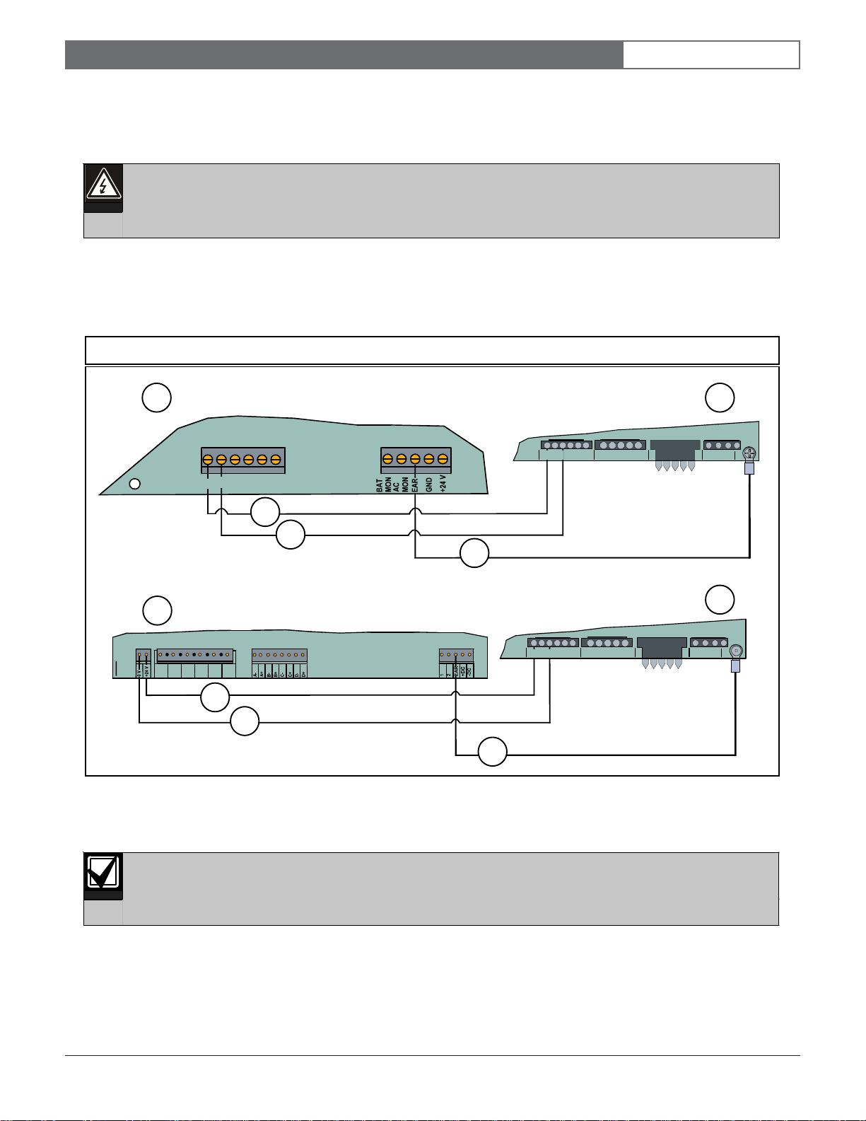
To connect the D9068 DACT to the D8024 FACP or the D10024 FACP (refer to Figure 1):
1. Attach the D9068 power (+) terminal to the FACP +24 V auxiliary power terminal.
2. Attach the D9068 power (-) terminal to the FACP 0 V auxiliary power terminal.
3. Attach the D9068 earth ground (green) to the FACP terminal labeled “EAR.”
Figure 1: D9068 to D8024 or D10024 Power Connections
EN | 3D9068 | Quick Start |
1
AUX
O/P
+24 V
0 V
A- A+ B- B+
SOUNDERS
-+
-
+
AB
21
345
KEYPAD
2
NC C NO
3
4
5
2
NC C NO
24 V AUX
6
NC NO COM NC NO COM
SOUNDER
OUTPUTS
+ -
KEYPAD
345
21
-+
AB
3
4
5
1 - D8024 FACP 3 - Power (+) terminal 5 - Earth ground (green)
2 - D9068 DACT 4 - Power (-) terminal 6 - D10024 FACP
The D9068 DACT draws a maximum of 192 mA. The FACP can provide up to 320 mA. Verify the total
draw on the FACP 24 V auxiliary power is less than 320 mA.
Bosch | 11/04 | 48575C
Page 4
1.0 D9068 to FACP Connections
EN | 4D9068 | Quick Start |
1.2 D9068 to D9052 Serial Connections
Use the D9068 DACT with the D8024 FACP and the D10024 FACP to send reports to a central station. You must
use a D9052 RS-232 Bus Module between the FACP and the D9068. Assign the FACP network Address 1. Refer to
Section 2.1 Setting the FACP’s Network Address (page 6) for instructions.
1. Install the D9052 on the D8024 Port C.
The D8024 cannot support the D9068 and a network connection simultaneously through Port C.
2. Connect the D9052 to the D10024 Port B.
Refer to the D9052 Installation Guide (P/N: 34096) for instructions on installing, addressing, and operating the
D9052 FACP.
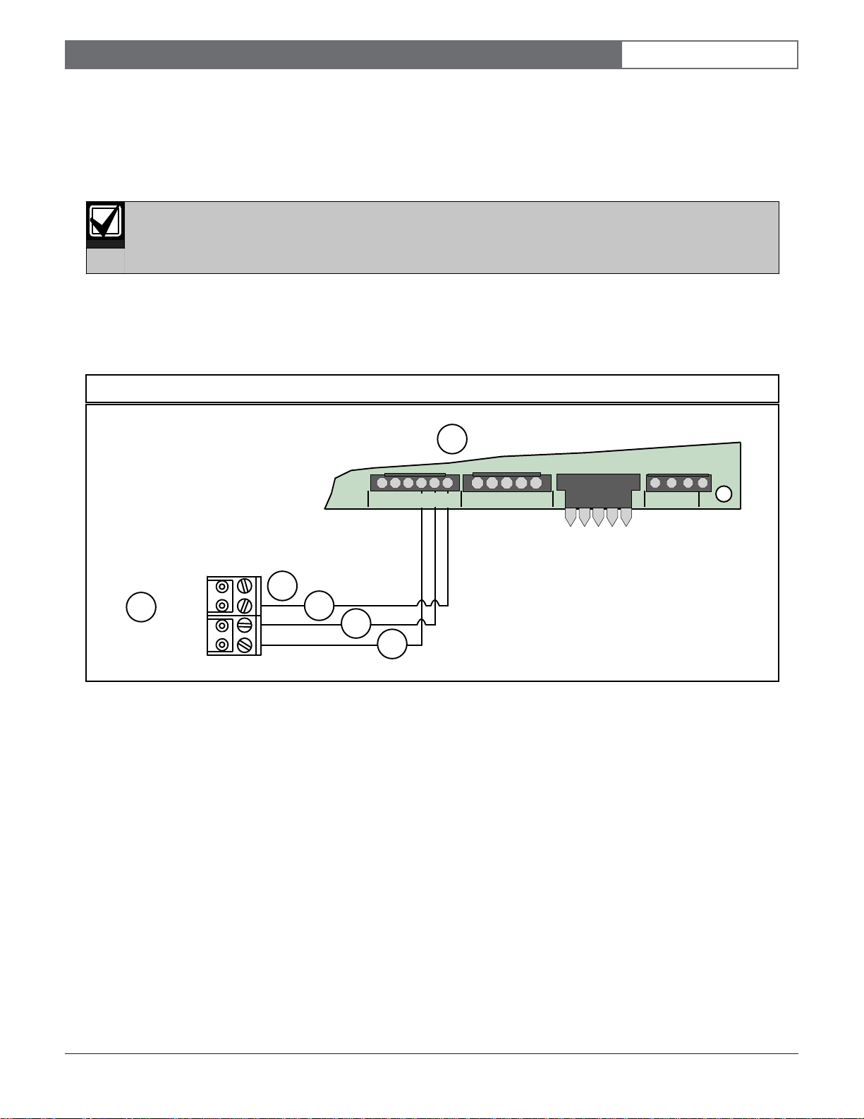
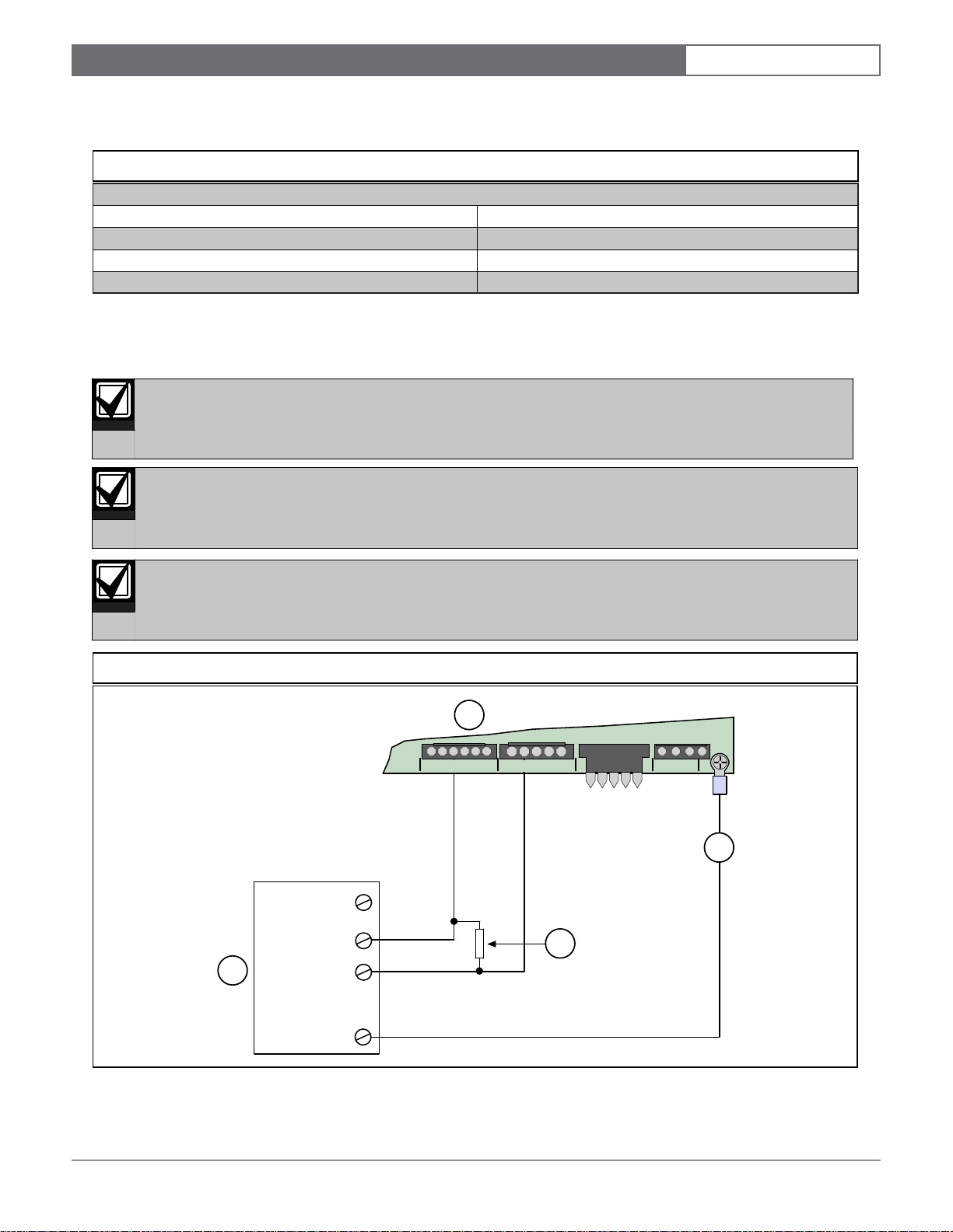
Figure 2 shows the D9068 to D9052 wiring connections.
Figure 2: D9068 to D9052 Wiring Connections
1
345
+
-AB
+
RTS
6
1 - D9068 3 - Serial transmit 5 - Ground
2 - Request to send (not used) 4 - Serial receive 6 - D9052
TX
RX
GND
2
3
4
5
2-1
KEYPAD
NC C NO
1.3 D9068 to FACP Relay Connections (Optional)
Use the D9068’s five inputs as back-up connections to an FACP. The D8024 and D10024 each provide two on-board
relays. Additional relay outputs can be added to the FACP using the D328A Addressable Analog Relay Modules.
Install and configure the relays to activate only for the specified FACP events. For additional information, refer to:
• D8024/D9024/D10024 Programming Guide (P/N: 38789) for FACP relay programming instructions
• D9068 Operation and Installation Guide (P/N: 45386) for D9068 detailed relay wiring instructions
• D328A Installation Instructions (P/N: 37095) for D328A wiring, addressing, and operating instructions
Bosch | 11/04 | 48575C
Page 5
1.0 D9068 to FACP Connections
EN | 5D9068 | Quick Start |
When using the D9068’s inputs as back-up connections, apply the mappings shown in Table 1 from the FACP event
to the D9068 input activation type.
Table 1: D9068 Input to FACP Event Messages
FACP General System Event D9068 Input Activation Type
Fault Event Fault on Short
AC Fail AC Fail
Common Fire Alarm
To access the D9068’s input point configuration from the D7033 keypad:
1. Press [0] [3]. The [0] is for Program, [3] is for Program Inputs.
2. Press the corresponding number key followed by [#] [1] to select a point number. [1] is for Configure.
The D9068’s inputs can only detect alarm (shorted) conditions when the RS-232 connection is broken.
When the RS-232 connection to the FACP is active, the inputs are not monitored.
When configured to the D8024 or D10024, only use the D9068’s five inputs as back-up connections.
These inputs cannot be used as separate or additional zone inputs.
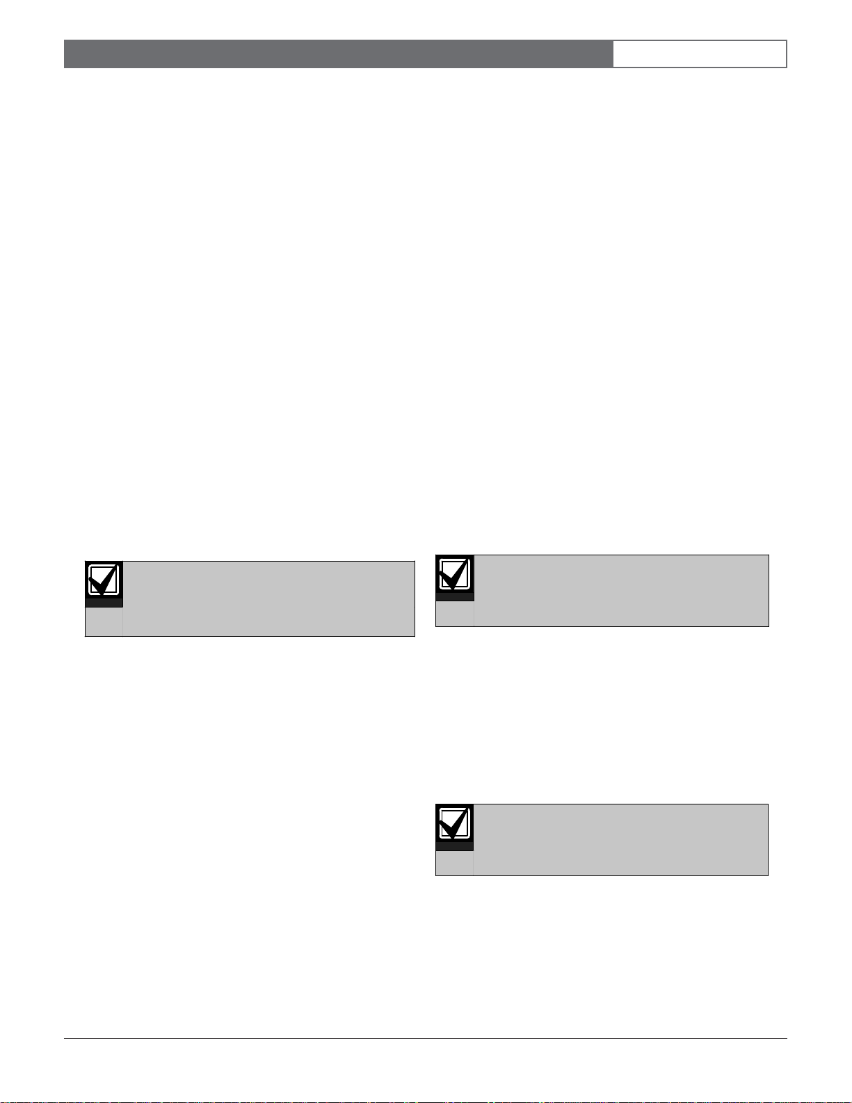
The input is supervised and requires an end-of-line (EOL) resistor connected as shown in
Figure 3: Basic D9068 Relay Connections
NC
Output
Relay
4
Earth Ground
C
NO
1
1
-+
-
+AB
345
2
.
KEYPAD
Figure 3
NC C NO
2
3
1 - D9068 3 - EOL resistor 2.21 kΩ, UL Listed, Bosch (P/N: 25899)
2 - Earth ground 4 - FACP
Bosch | 11/04 | 48575C
Page 6
2.0 FACP Programming
EN | 6D9068 | Quick Start |
2.0 FACP Programming
The D9068 must be connected to a FACP with a
network address of 1. Communication with the D9068 is
not possible if the FACP’s network address is set to any
other number. The D9068 uses network Address 0.
This section only provides the essential programming
steps required to set up the D8024 or D10024 for use
with the D9068.
2.1 Setting the FACP’s Network Address
To set the network address on the D8024 or D10024:
1. At the keypad, press the [>] key to display the Main
Menu.
2. Press the [1] key to select 1) Commission.
3. When the display prompts, Please key in
your passcode, enter the Control Level 3
passcode. The Commission Menu 1 appears.
4. Press [Yes] twice to scroll to Commission Menu 3.
5. Press [3] to enter Network options.
6. If the display prompts Memory Locked!, unlock
the memory by moving the Memory Lock switch
into the OPEN position. Refer to the D8024/D9024/
D10024 Programming Guide (P/N: 38789) for
Memory Lock Switch locations.
3.0 D9068 Programming
This section provides the programming steps required to
operate the D9068 with the D8024 or D10024. For
complete D9068 programming instructions, refer to the
D9068 Operation and Installation Guide (P/N: 45386).
3.1 D9068 Account Numbers
To set the D9068 account numbers:
1. At the Programming Menu, press [5] on the D7033
keypad to select PROG ACC’NTS.
2. Press [1] to select ACCOUNT NUMS.
3. Press the corresponding number key for the account
number you want to set. For example, press [1] for
Account #1 or press [2] for Account #2.
4. The existing number appears on the top line. You
can access the hexadecimal digits A through F by
pressing [TEST], and then pressing the
corresponding number keys. For example, press [1]
for A, [2] for B, [3] for C, [4] for D, [5] for E, and [6]
for F.
5. Enter the new number on the second line and press
[#] to confirm your entry. Press [* Clear] to return
to the Prog Acc’nts submenu. Program Account
Number 2 using this same procedure.
At the end of the programming session,
lock the memory. The FACP does not exit
Commissioning Mode unless the memory
is locked.
7. Press [3] to display Network Menu 1.
8. When the display prompts Panel Network -
address number?, press [1] to enter network
Address 1.
9. When you complete the control panel
programming, press [No] twice to return the FACP
to the normal operating mode. Then press [3] to
select 3) Normal Operation from Commission
Menu 1.
10. Move the Memory Lock Switch to the CLOSED
position.
“0000” is not a valid account number. At
least one digit must be non-zero.
3.2 D9068 Phone Numbers
To set the D9068 phone numbers:
1. At the Prog Acc’nts submenu, press [2] to select
PHONE NUMS.
The PHONE NUMS window appears.
2. Press the corresponding number key for the phone
number you want to set. For example, press [1] to
select Phone #1 or press [2] to select Phone #2.
Phone # 3 is currently not available at this
time. It is reserved for future use.
3. Enter the phone number. Press [Drill] and
[DISABLE] to move between digits. When your
entry is completed, press [#].
4. Press [* Clear] to return to the Prog Acc’nts
submenu.
Bosch | 11/04 | 48575C
Page 7
3.0 D9068 Programming
EN | 7D9068 | Quick Start |
You can include several special control characters in
your phone number using the [Test] key.
• * CODE:
Press [Test] and then press [1] for Touch Tone “*”
action.
• # CODE:
Press [Test] and then press [2] for Touch Tone “#”
action.
• /3 SEC DELAY:
Press [Test] and then press the [3] key for a
3-second delay.
3.3 D9068 Serial Port
To enable the D9068’s serial port:
1. At the Programming Menu, press [8] to select Serial
Connection.
2. Press [1] for Ye s .
Although the D9068 supervises its
connection to the D8024 and D10024, the
analog FACPs do not supervise the
connection of the D9068. If the RS-232 link
between the D9068 and FACP is broken,
the D9068 recognizes the problem but
the FACP does not.
For installations requiring the FACP to
recognize faults on the D9068, connect the
D9068 relay output to an analog input
module such as a D326A or D339A Point
Contact Module. On the FACP, configure
the points for action Fault. On the D9068,
configure the relay to Release on Trouble.
No individual restorals are sent. Only the
system Reboot/Reset Reports are sent
when the system is all clear.
When the FACP is in alarm, no FACP
Trouble Reports are sent. D9068 Trouble
Reports are still sent.
For the codes and events generated by the
D8024 and D10024 FACPs, refer to
Appendix F
Installation Guide
in the
D9068 Operation and
(P/N: 45386).
Bosch | 11/04 | 48575C
Page 8

Bosch
130 Perinton Parkway
Fairport, NY 14450-9199 USA
www.boschsecurity.us
Customer Service: (800) 289-0096
Technical Support: (888) 886-6189
© 2004 Bosch
48575C
 Loading...