

Bosch D344-RL Installation Manual
Installation Instructions
for the
D344-RL Remote Indicator Kit
1.0 Description
Use the D344-RL Remote Indicator Kit with the D340 Series
(D340/D341/D342/D343) Duct Smoke Detector Housings.
The D344-RL includes:
• Wiring harness (1)
• Mounting screws (2)
• D306 Remote Indicator Plate (1). This plate contains LED
indicators to determine the detector’s status and condition.
The D306 also has a point for reading and testing the
sensitivity voltage. Refer to Figure 1.
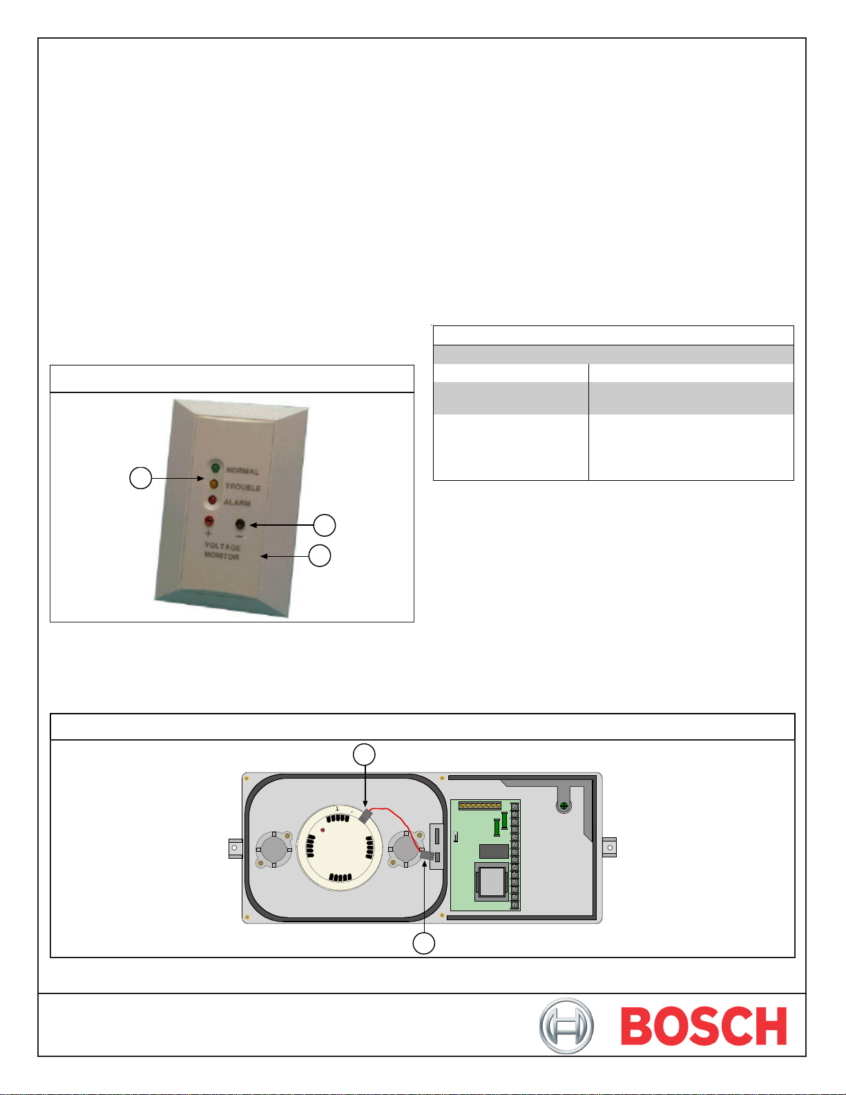
Figure 1: D306 Remote Indicator Plate
1
2.0 Installation
1. Ensure the D340 Series Housing you are using is installed
according to the appropriate installation instructions:
• D340 Installation Instructions (P/N: 48188)
• D341/D342 Installation Instructions (P/N: 48196)
• D343 Installation Instructions (P/N: 48199)
2. Ensure the detector is in proper working order.
3. Connect the wiring harness to the detector and the D340
Series Power Card (refer to Figure 2).
4. Connect the D306 according to the D306 Installation
Instructions (P/N: 32068).
3.0 Specifications
Table 1: Specifications
Voltage Requirements
Current Draw
Operating Temperature
Range
10 VDC to 32 VDC
10.0 mA at 24 VDC, standby
20.0 mA at 24 VDC, alarm
-22°F to +130°F (-30°C to +54°C)
For UL listed requirements, the
operating temperature range is
+32°F to +100°F (0°C to +37.8°C)
2
3
1 - LED indicators
2 - Sensitivity voltage indicators
3 - Removable cover. The two mounting screws are located
under this cover.
Figure 2: Wiring Harness Connector
1
2
1 - Harness connection to the detector 2 - Harness connection to the D340 Series Power Card

© 2006 Bosch Security Systems, Inc.
130 Perinton Parkway, Fairport, New York, USA 14450-9199
Customer Service: (800) 289-0096; Technical Support: (888) 886-6189
D344-RL Installation Instructions
P/N: 48255G Page 2
10/06
 Loading...