

Bosch D341P Installation Manual
D285DH
Installation Instructions
EN
Photoelectric Duct
Smoke Detector

D285DH | Installation Instructions |
1.0 Introduction
FCC Notice
The D285DH Photoelectric Duct Smoke Detector
complies with Part 15 of the Federal Communication
Commission (FCC) Rules. Operation is subject to the
following conditions:
• The detector might not cause harmful interference.
• The detector must accept any interference received,
including interference that can cause undesirable
operation.
Changes or modifications not expressly approved by
Bosch can void the user’s authority to operate the
D285DH detector.
1.0 Introduction
The D285DH is a UL Listed detector designed for use
with commercial fire protective signaling systems and
household fire warning systems. Refer to the National
Fire Alarm Code (NFPA 72).
When properly installed using the D285 Series
Dectectors, tamper protection is provided by the
positive power line in/out wiring. This causes the
control to initiate a trouble signal when a detector is
removed from its base. The master control provides
two-wire system supervision. An end-of-line (EOL)
resistor, specified by the control manufacturer, provides
four-wire supervision.
2.0 Specifications
Table 1: Specifications
Description
Operating
Temperature
Voltage and
Current
Power-up
Time
Compatible
Control
Panels
Only requires a base. “B” is the UL
compatibility identifier. Refer to the
Two-Wire Smoke Detector Compatibility
Technical Service Note
determine the identifier used with the
D340 Series Duct Housing.
+32°F to +100°F (0°C to +38°C)
0 to 95% relative humidity
(non-condensing)
Refer to the
Installation Instructions
D341/D342 Duct Detector
the
Installation Instructions
voltage and current.
22 sec maximum
Two-wire:
Refer to the
Compatibility Technical Service Note
(P/N: 31866).
Note: Bosch makes no claim written, oral,
or implied the D285DH works with
any two-wire control panels except
those specified in the
Smoke Detector Compatibility
Technical Service Note
(P/N: 31866).
Four-wire:
Compatible with all UL Listed four-wire
control panels. Refer to the
manufacturer's installation instructions for
proper EOL resistor selection.
(P/N: 31866) to
D340 Duct Detector
(P/N: 48188) and
(P/N: 48196) for
Two-Wire Smoke Detector
Two-Wire
Bosch | 6/04 | 49323C2
D285DH | Installation Instructions | 3.0 Mounting
3.0 Mounting
1. Before mounting, remove the dust cover from the
detector.
2. Mount the duct housing according to the
manufacturer’s instructions.
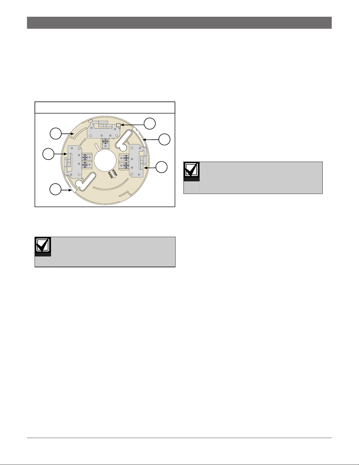
3. Mount the detector on the base by turning it
clockwise until it clicks into place (Figure 1).
Figure 1: Mounting the Base
1
2
R2
1
+1
2
1 - Base contacts (three sets)
2 - Start the detector contacts at these three places
and rotate the base clockwise.
3-
1
3. When the system is free of alarms, check each
detector to ensure the red LED head indicator
flashes approximately every 4 sec. This verifies the
detector is receiving power and operating properly.
4. Test each detector to ensure it will cause a control
panel alarm. This is the only way to ensure proper
operation. Alarm the detector in on of the following
methods:
a. If the duct housing cover is in position, place
a magnet horizontally against the recess in
the cover to activate an internal reed switch.
b. With duct housing cover removed, use a UL
2
5. Check the overall alarm loop loading by measuring
Listed aerosol smoke detector tester, such as
the Home Safeguard Industries’ 25S to
simulate an alarm. Follow the aerosol smoke
detector tester manufacturer’s instructions.
When a detector alarms, the red LED head
indicator activates and latches in the ON
position. Clear the alarm before proceeding
to the next detector.
the voltage across each EOL resistor. The voltage
should equal or exceed the minimum specified by
the control panel’s manufacturer.
The D285DH is keyed. Do not force a
detector onto its base.
4.0 Testing
1. Check the wiring from the control panel to the last
head on each run for proper polarity and continuity.
Ensure each run terminates with an EOL resistor as
specified by the control panel manufacturer.
2. Apply power to the system. Check for alarms and
troubles.
a. Note which detectors are in alarm (if any) and
shut down the system.
b. Remove these detectors from their bases and
recheck the bases for proper wiring. If the
problems persist, replace the affected
detectors or swap them with known good
units. This determines if the problem is
caused by the detector or the base.
c. In a system alarm with no detector alarms,
remove all detectors and check the wiring at
each base. Pay close attention to the wiring of
each EOL resistor.
3Bosch | 6/04 | 49323C
 Loading...