

Bosch D300A-HV Installation Manual
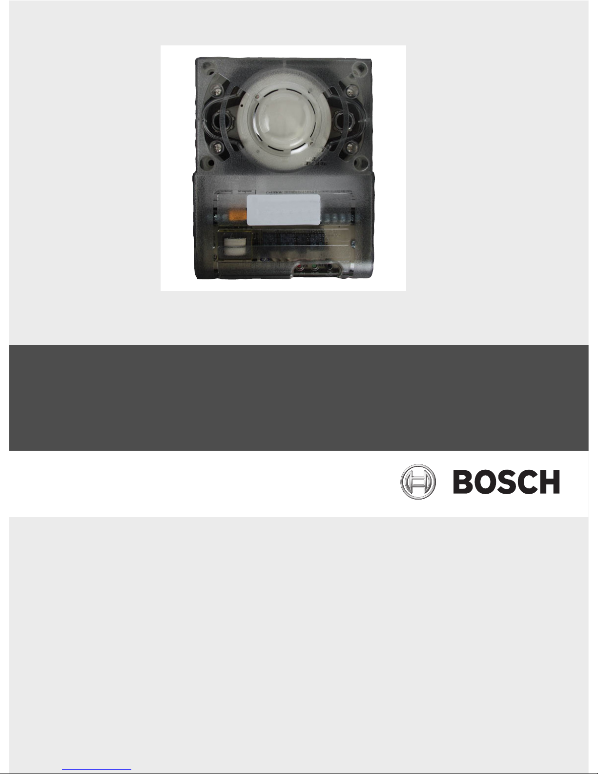
High-Voltage Conventional Duct Detector
D300A-HV
en Installation Guide


High-Voltage Conventional Duct Detector Table of Contents | en 3
Bosch Security Systems, Inc. Installation Guide F.01U.035.635 | 5.0 | 2011.09
Table of Contents
1Notice 4
2Overview 4
3 Mounting 4
3.1 Preparing the Duct 4
3.2 Verifying Air Flow and Direction 5
3.3 Assembling the Intake Sampling Tubes 6
3.4 Mounting the Intake Sampling Tubes 6
3.5 Mounting the Detector 6
3.6 Verifying the Air Sampling 6
4 Wiring 6
4.1 Testing 8
4.2 Replacing the Detector Head 8
5 Specifications 8
4 en | Notice High-Voltage Conventional Duct Detector
F.01U.035.635 | 5.0 | 2011.09 Installation Guide Bosch Security Systems, Inc.
1Notice
Use these instructions when installing the D300A-HV High-Voltage Conventional Duct Detector
in a system controlled by a fire alarm control panel (FACP). Install, test, and maintain the
D300A-HV according to these instructions, NFPA 72, local codes, and the Authority Having
Jurisdiction (AHJ).
2Overview
The D300A-HV High-Voltage Conventional Duct Detector Housing unit is an accessory device
complete with a photoelectric smoke detector head used in HVAC duct works. It can be
powered by 24 VAC, 24 VDC, or 230 VAC and is intendend for high-voltage applications. Air
sampling is accomplished by two tubes that protrude into the duct. An exhaust tube of one
standard length is supplied in the installation kit with the duct detector housing unit. Once
the duct width is determined, the air intake sampling tubes must be ordered. Sampling tubes
are supplied in three standard lengths and cut to size to fit the duct. The air samples are
collected by positive pressure to the detector head. Output terminals are provided for remote
accessories such as remote status indicators (LEDs), reset keyswitches, and push buttons.
3 Mounting
3.1 Preparing the Duct
When preparing the duct, refer to Figure 3.1 on page 5.
1. Remove the paper backing from the mounting template included in the Installation Kit.
2. Attach the template to the duct at the desired location.
3. Using the template as a guide, drill four mounting holes (3/32 in. [2.38 mm] diameter) for
the duct mounting screws (four #12 x ½ in. [1.27 cm] sheet metal screws packaged in
installation kit).
4. Drill or punch holes for the sampling tubes in the air duct (1.375 in. [3.49 cm])
5. Clean all holes.
NOTICE!
– Failure to follow these instructions can cause the device to not properly operate.
– Bosch is not responsible for improperly installed, tested, or maintained devices.
– NFPA 72 requires a complete, system-wide Functional Test be performed after making
modifications, repairs, upgrades, or adjustments to the system’s components, hardware,
wiring, programming, software, or firmware.
– The D300A-HV is not intended for open area protection. Refer to the NFPA 90A and
NFPA72E , for general and additional duct smoke detector operation and installation.
DANGER!
Follow the procedures in these instructions to avoid personal injury and/or damage to the
equipment.
CAUTION!
To prevent false alarms, do not mount the D300A-HV Duct Detectors in areas:
– of extreme high or low temperatures,
– where high humidity exists,
– where duct air might contain gases or excess dust.
Refer to NFPA 90A, NFPA 72E, and NFPA 101. Also refer to Section 5.0 Specifications.
 Loading...