

Page 1
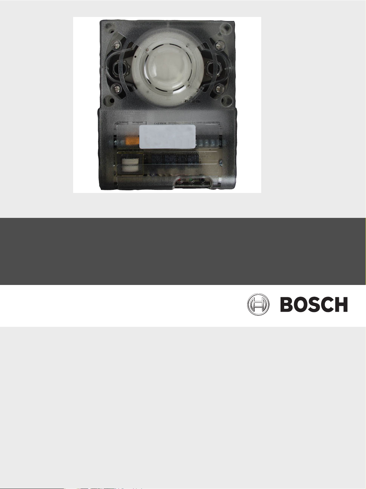
Conventional Duct Detector
D300A
en Installation Guide
Page 2

Page 3

Conventional Duct Detector Table of Contents | en 3
Table of Contents
1Notice 4
2Overview 4
3 Mounting 4
3.1 Preparing the Duct 4
3.2 Verifying Air Flow and Direction 5
3.3 Assembling the Intake Sampling Tubes 6
3.4 Mounting the Intake Sampling Tubes 6
3.5 Mounting the Detector 6
3.6 Verifying the Air Sampling 6
4 Wiring 6
4.1 Testing 8
4.2 Replacing the Detector Head 8
5 Specifications 8
Bosch Security Systems, Inc. Installation Guide F.01U.252.768 | 5.0 | 2011.09
Page 4
4 en | Notice Conventional Duct Detector
1Notice
Use these instructions when installing the D300A Conventional Duct Detector in a system
controlled by a fire alarm control panel (FACP). Install, test, and maintain the D300A
according to these instructions, NFPA72, local codes, and the Authority Having Jurisdiction
(AHJ).
NOTICE!
– Failure to follow these instructions can cause the device to not properly operate.
– Bosch is not responsible for improperly installed, tested, or maintained devices.
– NFPA 72 requires a complete, system-wide Functional Test be performed after making
modifications, repairs, upgrades, or adjustments to the system’s components, hardware,
wiring, programming, software, or firmware.
– The D300A is not intended for open area protection. Refer to the NFPA90A and NFPA72E
, for general and additional duct smoke detector operation and installation.
DANGER!
Follow the procedures in these instructions to avoid personal injury and/or damage to the
equipment.
2Overview
The D300A Conventional Duct Detector Housing unit is an accessory device complete with a
photoelectric smoke detector head used in HVAC duct works. It can be powered by 24 VAC,
24 VDC, or 115 VAC. Air sampling is accomplished by two tubes that protrude into the duct.
An exhaust tube of one standard length is supplied in the installation kit with the duct
detector housing unit. Once the duct width is determined, the air intake sampling tubes must
be ordered. Sampling tubes are supplied in three standard lengths and cut to size to fit the
duct. The air samples are collected by positive pressure to the detector head. Output
terminals are provided for remote accessories such as remote status indicators (LEDs), reset
keyswitches, and push buttons.
3 Mounting
CAUTION!
To prevent false alarms, do not mount the D300A Duct Detectors in areas:
– of extreme high or low temperatures,
– where high humidity exists,
– where duct air might contain gases or excess dust.
Refer to NFPA90A, NFPA72E, and NFPA101.
3.1 Preparing the Duct
When preparing the duct, refer to Figure 3.1 on page 5.
1. Remove the paper backing from the mounting template included in the Installation Kit.
2. Attach the template to the duct at the desired location.
3. Using the template as a guide, drill four mounting holes (3/32 in. [2.38 mm] diameter) for
the duct mounting screws (four #12 x ½ in. [1.27 cm] sheet metal screws packaged in
installation kit).
4. Drill or punch holes for the sampling tubes in the air duct (1.375 in. [3.49 cm])
5. Clean all holes.
F.01U.252.768 | 5.0 | 2011.09 Installation Guide Bosch Security Systems, Inc.
Page 5

Conventional Duct Detector Mounting | en 5
3.2 Verifying Air Flow and Direction
Use the D300A in ducts with air velocities between 300 ft to 4000 ft (91 m to 1219 m) per
minute. Verify the air velocity by checking the duct installation specifications, or by using an
Alnor Model 6000P (or equivalent) velocity meter. Refer to Figure 3.2 on page 5 for sampling
tube orientation to air flow direction.
Figure 3.1 Mount the Duct Housing
1 - Six duct widths (minimum) from any
7 - Exhaust tube
bend or other obstruction
2 - Air duct (number varies according to
8 - Set screws (2)
tube length)
3 - Template 9 - Intake sampling tube connectors (2)
4 - Stopper 10 - Duct mounting screws (2)
5 - Air flow for this illustration 11 - Top of the D300A Housing
6 - Intake sampling tube
1
Figure 3.2 Intake Sampling Tube Orientation
1 - Insert stopper at this end of the
5 - Exhaust tube (2)
intake sampling tube.
2 - Air flow 6 - Air hole (number varies according to tube
length)
3 - Intake sampling tube (2) 7 - Set screws (4)
4 - Duct width* 8 - Top of the D300A Housing
* Support the intake sampling tube where the duct width is greater than 3 ft (91 cm).
Bosch Security Systems, Inc. Installation Guide F.01U.252.768 | 5.0 | 2011.09
Page 6

6 en | Wiring Conventional Duct Detector
3.3 Assembling the Intake Sampling Tubes
The intake sampling tube is a piece of steel piping with a series of holes drilled along its entire
length, extending the entire width of the duct. Ensure the holes face into the airflow. Exhaust
tubes are pieces of steel piping approximately 7.5 in. (19 cm) long. The sampling tubes come
in the standard lengths shown in the table 3.1. You need to cut them to fit in the duct.
Model Number Sampling tube length
FAA-325-2.5 2.5 ft (76 cm)
FAA-325-5 5 ft (152.5 cm)
FAA-325-10 10 ft (305 cm)
Tab le 3 .1 Intake Sampling Tube Standard Lengths
1. Prepare the intake sampling tubes by cutting them to the desired lengths.
2. Insert the stopper, included in the Installation Kit, into the end of the intake sampling
tube.
3.4 Mounting the Intake Sampling Tubes
The intake sampling tube connectors are equipped with set screws that allow you to mount
the tubes only in the directions shown in Figure 3.2 on page 6. Consider the airflow direction
when orienting the intake sampling tubes.
1. Insert the intake sampling tubes and exhaust tubes into the connectors.
2. Align the set screws to the set screw holes in the tubes and tighten.
Refer to Figure 3.1 on page 5 for mounting details.
3.5 Mounting the Detector
1. Position the detector and intake sampling tube assembly in the desired location.
2. Using four duct mounting screws (four #12 x ½ in. [1.27 cm] sheet metal screws included
in the installation kit), secure the detector and the intake sampling tube assembly to the
duct.
3.6 Verifying the Air Sampling
Use a Dwyer Model 4000 Differential Pressure Gauge or its equivalent to verify the correct air
sampling. Ensure the pressure differential between the input sampling tube and exhaust tube
is greater than 0.01 in. (0.25 mm) and less than 1 in. (3 cm) of water.
Refer to Figure 3.2 on page 6 for the intake sampling tube orientation to air flow direction. If
the pressure is more than this pressure range then cover holes uniformly across the length of
the tube. If the pressure is to low then drill holes uniformly across the length of the tube. The
holes should be the same size as the holes that exist.
4 Wiring
NOTICE!
Ensure that power is removed from all wiring before routing.
Observe polarity.
Wiring must conform to applicable local codes, ordinances, and regulations covering this type
of device. Wire the detectors according to the engineering drawing for that particular job
requirement. For D300A wiring details, refer to Figures 4.1 on page 8. Terminals are suitable
for up to 14 AWG (1.8 mm) wire.
F.01U.252.768 | 5.0 | 2011.09 Installation Guide Bosch Security Systems, Inc.
Page 7

Conventional Duct Detector Wiring | en 7
1
3
15
14
15
14
11
11
12 12
2
2
CAUTION!
Do not use looped wire under Terminals. Run break wire to provide supervision of
connections.
To wire the D300A:
1. De-energize the power source.
2. Wire all connections according to the engineering drawings.
3. Verify the system wiring.
4. Energize the detector.
Figure 4.1 Wiring the D300A Terminals
1 - Switched Power connections upon
5 - Alarm contacts 1 A at 24 VDC
reset (connect items 2 or 3, not both)
2 - 115 VAC 60 Hz input at 0.1 A
6 - Trouble contacts 10 A at 115 VAC*
maximum
3 - 24 VAC/VDC 60 Hz input at 0.1 A
7 - Remote accessories
maximum (detector only). Up to 1.9 A
for auxiliary outputs.
4 - Alarm contacts 10 A at 115 VAC
* Trouble contacts are shown in non-energized condition. Trouble contacts monitor power
connected and head removed.
Figure 4.2 Wiring the D300A to an FACP
1 - UL Listed FACp 3 - EOL Device
2 - D300A Detector
Bosch Security Systems, Inc. Installation Guide F.01U.252.768 | 5.0 | 2011.09
Page 8

8 en | Specifications Conventional Duct Detector
1
18
19
2
3
15 m A
@ 24 VDC
4
Figure 4.3 Remote Access Memory
1 - 1.2 kΩ, 1 W current-limiting resistor 4 - Red (+)
2 - Black (-) 5 - Key or push button “Test/Reset” switch
3 - Red alarm LED 6 - Green “Pilot” LED
4.1 Testing
The D300A photoelectric detector has a built-in sensitivity window verification feature. If the
detector is within its calibrated sensitivity range, the detector LEDs flash green in standby or
normal operation. If the detector drifts outside its sensitivity range, the LEDs flash red to
indicate an out of sensitivity condition. Bosch D1000 Calibrated Smoke Detector Tester may
also be used to check sensitivity.
17
16
20
16
5
4 A @
24 VDC
1
2
6
15 m A
@ 24 VDC
4
4.2 Replacing the Detector Head
If the detector head supplied with the D300A must be replaced, only replace the existing head
with a D282A-DH Replacement Photoelectric Smoke Detector Head.
1. Remove the four screws holding the detector’s cover.
2. Remove the existing detector head by twisting it counterclockwise.
3. Insert the D282A-DH and turn it clockwise.
4. Replace the detector’s cover and tighten the screws.
5 Specifications
Standby Current 20 mA at 24 VAC
Alarm Current 95 mA at 24 VAC
Alarm Relay Contact Rating 10 A maximum at 125 VAC resistive
Trouble Relay Contact Rating 10 A maximum at 125 VAC resistive
Sensitivity Range (Factory Set) 1.5%/ft to ~2.75%/ft (4.8%/m to ~ 8.7%/m)
Differential Pressure 0.01 in. (0.25 mm) - 1 in. (3 cm) of water
13 mA at 24 VDC
14 mA at 115 VAC
60 mA at 24 VDC
28 mA at 115 VAC
F.01U.252.768 | 5.0 | 2011.09 Installation Guide Bosch Security Systems, Inc.
Page 9

Conventional Duct Detector Specifications | en 9
Air Velocity 300 ft/min to 4000 ft/min (91 m/min to 1219 m/
min)
Ambient Temperature +32°F to +120°F (0°C to +49°C)
Humidity 10% RH to 85% RH (non-condensing)
Intake Sampling Tubes FAA-325-2.5: 2.5 ft (0.8 m)
FAA-325-5: 5.0 ft (1.5m)
FAA-325-10: 10 ft (3m)
Replacement Detector Head D282A-DH Replacement Photoelectric Smoke
Detector Head
Bosch Security Systems, Inc. Installation Guide F.01U.252.768 | 5.0 | 2011.09
Page 10

10 en | Specifications Conventional Duct Detector
F.01U.252.768 | 5.0 | 2011.09 Installation Guide Bosch Security Systems, Inc.
Page 11

Page 12

Bosch Security Systems, Inc.
130 Perinton Parkway
NY 14450 Fairport
USA
www.boschsecurity.us
© Bosch Security Systems, Inc., 2011
 Loading...