

D287/D288/D292/D293A/D293E
Installation Instructions
EN
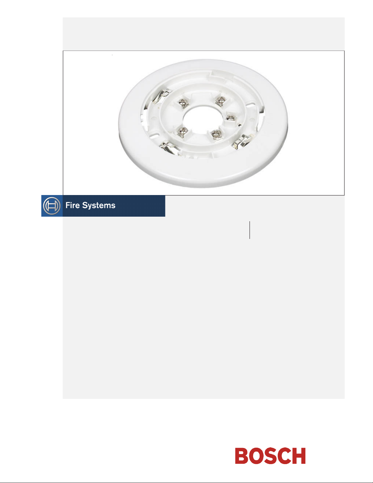
Smoke Detector Bases

D287/D288/D292/D293A/D293E | Installation Instructions |
1.0 Overview
1.0 Overview
The D287/D288/D292/D293A/D293E Smoke Detector
Bases are designed for use with the D286 Ionization
Smoke Detector, D285/D285TH Photoelectric Smoke
Detectors, and D603/D604/D605 Heat Detectors.
Install these bases according to the National Fire Alarm
Code, NFPA 72.
Before installing a smoke detector base, read and
understand this and the following documents to ensure
proper system operation:
• D285/D285TH Installation Instructions (P/N: 32029)
• D286 Installation Instructions (P/N: 32035)
• D603/D604/D605 Installation Instructions
(P/N: 45570)
• NFPA Standard 72
This document covers only the information necessary to
mount and wire the bases. Other information is
available from:
• Two-wire compatibility information in the Technical
Service Note: Two-Wire Smoke Detector Compatibility
(P/N: 31866).
• Installation guidelines in the Technical Service Note:
Smoke Detector Installation Considerations (P/N: 31347).
• Information about power requirements, testing, and
maintenance in the D285/D285TH Installation
Instructions (PN: 32029), D286 Installation Instructions
(PN: 32035), and D603/D604/D605 Installation
Instructions (PN: 45570).
- D287 Base only, two-wire
- D288 Base only, two-wire, wide diameter
- D292 Base only, four-wire
- D293A Base only, four-wire, Form “C”
Auxiliary relay
- D293E Base only for power supervision, four-
wire, end-of-line (EOL) relay, Normally
Open (N/O) auxiliary relay
- D293S Base only, four-wire with sounder
- D275 EOL supervision module for four-wire
systems
“A” is the Underwriters Laboratories, Inc. (UL)
compatibility identifier for the D286, D285/D285TH,
D603/D604/D605 Smoke Detectors. To determine the
identifier used with the D287, refer to the Technical
Service Note: Two-Wire Smoke Detector Compatibility
(P/N: 31866).
Detector Power Requirements
• Standby voltage: Two-wire. 8.5 VDC to 33.0 VDC
Four-wire 10 VDC to 30 VDC
Alarm Current
• Two-wire. Dependent on the control panel that must
limit the alarm current to 100 mA maximum.
• Four-wire
- D292: 52 mA at 12 VDC
54 mA at 24 VDC
(70 mA maximum at 30 VDC)
- D293A: 58 mA at 12 VDC
62 mA at 24 VDC
(75 mA maximum at 30 VDC)
- D293E: 82 mA at 12 VDC
86 mA at 24 VDC
(100 mA maximum at 30 VDC)
- D293S: 52 mA at 12 VDC
54 mA at 24 VDC
Sounder 15 mA at 12 VDC, 25 mA
at 24 VDC
Bosch | 6/04 | 31348G2
D287/D288/D292/D293A/D293E | Installation Instructions | 2.0 Mounting
2.0 Mounting
1. Select mounting locations based on the Technical
Service Note: Smoke Detector Installation Considerations
(P/N: 31347).
2. Pre-run all system wiring to the base locations.
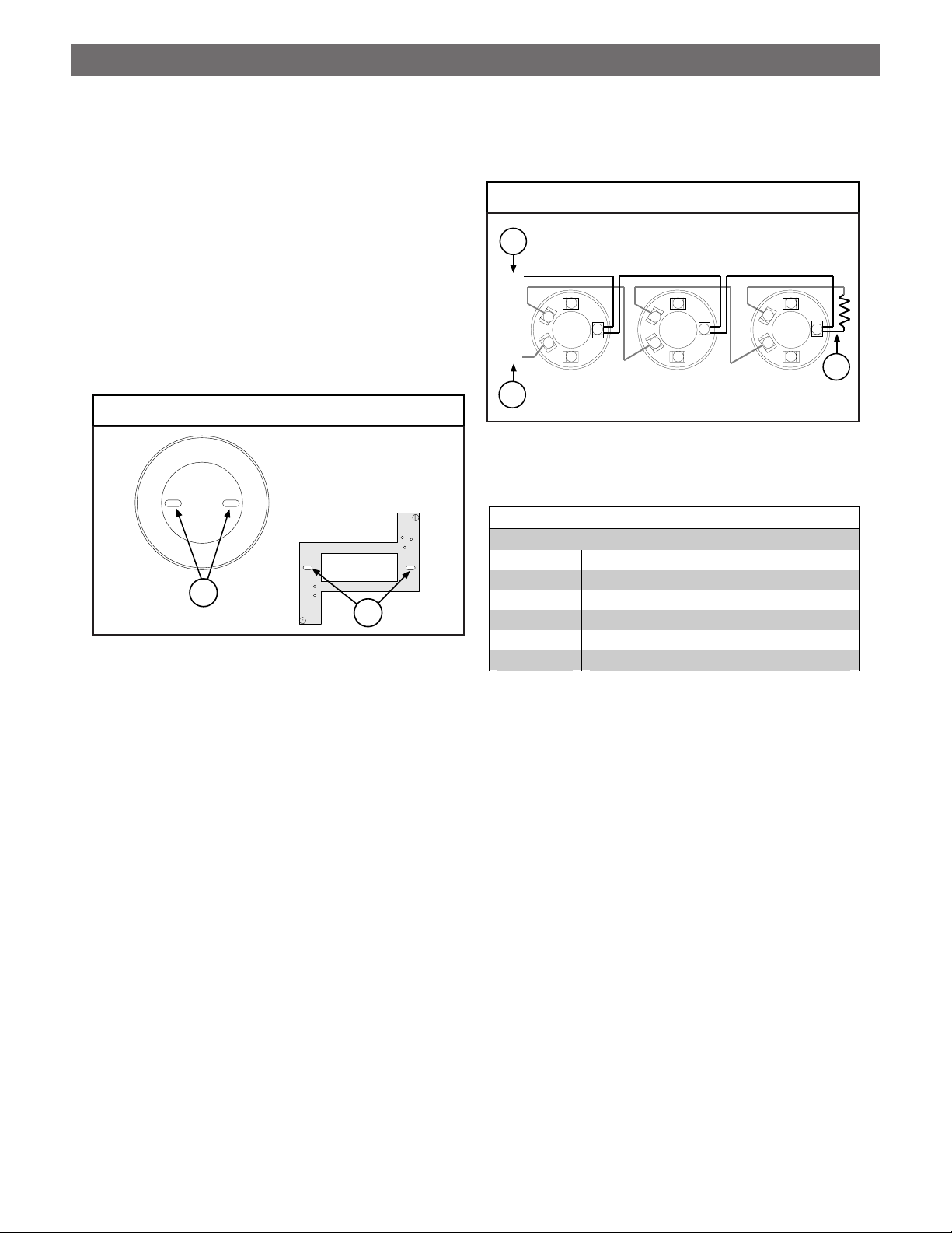
3. Mount the base using the two oblong mounting
holes.
4. Tighten the base to the mounting surface.
5. If mounting to 4 in. (10 cm) square boxes, use the
adapter plate. First, mount the adapter plate to the
box, then mount the base to the adapter plate and
box using the oblong mounting holes. Refer to
Figure 1.
Figure 1: Adapter Plate Connections
1
2
1 - Adapter plate mounting holes (2)
2 - Base to adapter plate mounting holes (2)
3.0 Two-Wire Detector Wiring
Refer to Figure 2 and Table 1 for the D287 and D288
terminal functions.
Figure 2: D287 Wired in a Two-Wire Configuration
1
(–)
33
2
1
(+)
4
5
2
1
4
55
2
1 - Two-wire loop
2 - Compatible
3 - EOL resistor
Table 1: Terminal Functions
Terminal Function
1 Alarm loop positive (+) IN
2 Alarm loop positive (+) OUT
3 Remote LED output
4 Alarm loop negative (-)
5 No connection
3
2
1
4
3
Depending on local regulations, the bases might be
surface mounted using anchors, mollies, or wing
nuts. The bases might also be directly mounted to
4 in. (10 cm) octagonal electrical boxes or single
gang switch boxes.
Ensure the volume of any electrical box you use
accommodates the number and size of conductors as
specified by the National Electrical Code (NEC) or
any local regulations having jurisdiction.
6. Review Section 3.0 Two-Wire Detector Wiring and
Section 4.0 Four-Wire Detector Wiring on page 4 for
wiring information.
7. Connect the wiring to the bases.
3Bosch | 6/04 | 31348G

D287/D288/D292/D293A/D293E | Installation Instructions |
4.0 Four-Wire Detector Wiring
4.0 Four-Wire Detector Wiring
4.1 Terminal Connections
Do not twist wires or loop the wires around terminals.
Cut, strip, and insert the In/Out wires as individual ends
for terminal connection.
4.2 EOL Resistors
Use the EOL resistors supplied or ones specified by the
control panel manufacturer. This includes EOL resistors
used with the D275 Module.
4.3 D275 Power Supervision Relay
Refer to Figure 3 for the D275 wiring.
Figure 3: D275 Wring
4
3
1
(+)
(–)
2
2
1
546
3
A
B
C
D
5
4.4 Terminal Functions
Refer to Table 2 and Figures 4 through 6 for the D292
and D293A terminal functions.
Table 2: Four-Wire Terminal Functions
Terminal Function
1 DC power (+) IN
(No connection for D293E)
2 DC power (+) OUT
(DC power [+] IN for D293E)
3 Remote LED output
4 DC power negative (-)
5 Alarm loop (N/O)
6 Alarm loop (C)
When operating the D292, D293A, or
D293E in a 24 VDC system, cut the yellow
voltage jumpers on each base.
4.5 D292
Refer to Figure 4 for the D292 wiring.
Figure 4: D292 Wired in a Four-Wire Configuration
1
5
1 - Smoke
2 - Power
3 - Alarm loop
4 - EOL power supervision module
A = Red [+12 V], B = Yellow wire [+24 V],
C = Black wire [-], D = Blue wires
5 - EOL resistor
When using the D275 with 12 VDC systems, connect
the red wire to Terminal 2 on the last base in the run.
The yellow wire remains unconnected.
When using the D275 with 24 VDC systems, connect
the yellow wire to Terminal 2 on the last base in the run.
The red wire remains unconnected.
Use one D275 per loop with the D292 and D293A.
3
2
2
1
(+)
3
(–)
546
3
2
1
546
3
2
1
4
A
B
D
C
546
6
1 - Cut loop for 24 VDC
2 - Smoke
3 - Power
4 - Alarm loop
5 - EOL power supervision module
A = Red [+12 V], B = Yellow wire [+24 V],
C = Black wire [-], D = Blue wires
6 - EOL resistor
The D292 is the standard smoke detector base used in
four-wire configurations. The Alarm Loop relay
(Terminals 5 and 6) is a N/O relay rated at 10 W, 0.5 A
at 100 VDC. The relay closes on alarm.
Bosch | 6/04 | 31348G4

D287/D288/D292/D293A/D293E | Installation Instructions | 4.0 Four-Wire Detector Wiring
4.6 D293A
Refer to Figure 5 for the D293A wiring.
Figure 5: D293A Auxiliary/Alarm Contact Wiring
Do not use the D293E with inductive or
capacitive loads.
N/C N/OC
9
1
1 - Form “C” auxiliary
2 - N/O alarm
6
78
5
2
The D293A provides a N/O Alarm Loop relay and an
auxiliary set of Form “C” (NC/C/NO) contacts. The
contacts are rated at 62.5 VA, 0.5 A at 125 VAC and at
30 W, 1.0 A at 30 VDC for resistive loads.
Do not use the D293A with inductive or
capacitive loads.
4.7 D293E Power Supervision Base
Refer to Figure 6 for the D293E wiring.
Figure 6: D293E Power Supervision Base
2
(–)
(+)
3
4
5
1 - Cut loop for 24 VDC
2 - Smoke
3 - Power
4 - Alarm loop
5 - N/O auxiliary
6 - EOL resistor
1
3
2
1
4
56789
6
The D293E also provides EOL power supervision using
a built-in relay. This eliminates the need for separate
power supervision devices such as the D275. Only use
one D293E base per zone run; it must be the last base
on the run.
The EOL relay is rated at 10 W, 0.5 A at 100 VDC for
resistive loads.
4.8 Remote Alarm Indicator
Using the SMK-RA5 Alarm Indicator, connect the
positive (Item 1 in Figure 7) lead to Terminal 3 and the
negative lead (Item 4 in Figure 7) to Terminal 4.
Figure 7: SMK-RA5 Remote Alarm Indicator Wiring
1
2
2
3
1
1 - Red wire
2 - SMK-RA5 Annunciator
3 - Alarm
4 - White wire
5 - Two-wire detector base
4
3
5
5
4
The D293E provides a N/O Alarm Loop relay and an
auxiliary set of N/O contacts. The contacts are rated at
62.5 VA, 0.5 A at 125 VAC, and at 30 W, 1.0 A at
30 VDC for resistive loads.
5Bosch | 6/04 | 31348G

D287/D288/D292/D293A/D293E | Installation Instructions |
Notes
Bosch | 6/04 | 31348G6

D287/D288/D292/D293A/D293E | Installation Instructions
Notes
7Bosch | 6/04 | 31348G

Bosch
130 Perinton Parkway
Fairport, NY 14450-9199 USA
Customer Service: (800) 289-0096
Technical Support: (888) 886-6189
© 2004 Bosch
31348G
 Loading...