

Bosch D285, D285TH Installation Instructions Manual
D285/D285TH
Installation Instructions
EN
Photoelectric Smoke
Detectors

D285/D285TH | Installation Instructions |
1.0 Overview
FCC Notice
The D285 Series Photoelectric Smoke Detectors (D285,
D285TH) comply with Part 15 of the Federal
Communications Commission (FCC) Rules. Operation
is subject to the following two conditions:
1. These detectors might not cause harmful
interference.
2. These detectors must accept any interference
received, including interference that might cause
undesirable operation.
Changes or modifications not expressly approved by
Bosch can void the user’s authority to operate the D285
Series Smoke Detectors.
1.0 Overview
The D285 Series are UL Listed, open-area,
photoelectric, smoke detectors designed for use with
commercial fire protective signaling systems and
household fire warning systems (refer to the National
Fire Alarm Code [NFPA 72]). These detectors are
available in two-wire and four-wire models, and have an
optional +135°F (+57°C) fixed-temperature heat sensor.
For commercial and industrial installations, space the
detectors 30 ft (9.2 m) apart as recommended by
NFPA 72.
When properly installed using the D280/D290 Series
Detector Bases, tamper protection is provided by in/out
wiring of the positive power line. This causes the
control to initiate a trouble signal when a detector is
removed from its base. The master control supervises
the two-wire systems. Four-wire system supervision is
provided by an end-of-line (EOL) power supervision
device such as a D275 or a D293E Power Supervision
Base and an EOL resistor (as specified by the control
manufacturer).
Refer to Table 1 for product descriptions.
Table 1: Product Description
D285
D285TH
D285DH
D287
D292
D293A
D293E
D293S
D275
TP280
Detector only (requires base)
Detector with integral +135°F (+57°C) heat
sensor (requires base)
Detector only, for D340 Series Duct Smoke
Detectors
Base only, two-wire
Base only, four-wire
Base only, four-wire, Form “C” auxiliary relay
Base only for power supervision, four-wire,
EOL relay, Normally Open auxiliary relay
Base only, four-wire, with sounder
EOL supervision module for four-wire systems
Trim Plate 6 in. (16.2 cm) diameter
The letter “A” is the UL compatibility identifier for the
D285 Series. Refer to the Two-Wire Smoke Detector
Compatibility Technical Service Note (P/N: 31866) to
determine the UL compatibility identifier used with the
D287 Base.
Table 2: Specifications
Operating
Temperature
Power Requirements
Standby
Voltage:
Maximum
RMS Ripple:
Start-up
Current:
Standby
Current:
Note: The D293E equals 24 mA at 12 VDC and 24 VDC.
Alarm Current
Two-wire:
Four-wire:
Power-up
Time:
Compatible Control Panels
Two-wire:
Four-wire:
+32° to 100°F (0°C to +38°C )
0 to 95% relative humidity
(non-condensing)
Two-wire: 8.5 VDC to 33 VDC
Four-wire: 10 VDC to 30 VDC
25% of DC input
120 µA maximum
80 µA at 12 VDC
90 µA at 24 VDC
100 µA at 33 VDC
Dependent on the control panel that limits
the alarm current to 100 mA maximum.
D292: 48 mA at 24 VDC and 51 mA at
24 VDC (70 mA maximum at 30 VDC)
D293E: 80 mA at 12 VDC and 24 VDC
(100 mA maximum at 30 VDC)
D293S: Base 48 mA at 12 VDC, sounder
15 mA at 12 VDC, 25 mA at
24 VDC
22 sec maximum
Refer to the
Compatibility Technical Service Note
(P/N: 31866).
Note: Bosch makes no claim (written, oral,
or implied) the D285 Series Smoke
Detectors work with any two-wire control
panels except those specified in the
Two-Wire Smoke Detector Compatibility
Technical Service Note
Compatible with all UL Listed four-wire
control panels. Refer to the
manufacturer's installation instructions for
proper EOL resistor selection.
Two-Wire Smoke Detector
(P/N: 31866).
Bosch | 6/04 | 32029E2
D285/D285TH | Installation Instructions | 2.0 Mounting
2.0 Mounting
1. Before mounting, remove the dust cover from the
detector. The dust cover can be replaced during
construction periods, but it must be removed once
the alarm system is enabled.
The tamper screw is located in the recess
on the top of the dust cover.
2. Mount the base according to its instructions.
3. Mount the detector to the base by turning it
clockwise until it clicks into place. When it is secure,
the alignment line aligns with the tamper screw hole
(refer to Figure 1).
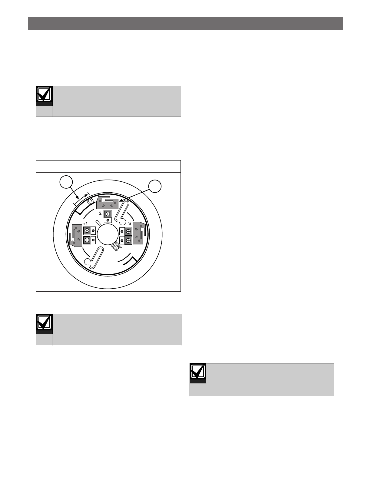
Figure 1: Mounting the Base
1
1 - Alignment arrow
2 - Base contacts (three sets)
The D285 Series Smoke Detectors are
keyed. Do not force a detector onto its
bases.
2
3.0 Installation Testing
1. Check the wiring from the control panel to the last
head on each run for proper polarity and continuity.
a. Ensure each run terminates with an EOL
resistor as specified by the control panel
manufacturer.
b. Ensure the four-wire runs terminate with EOL
modules or D293E Bases.
2. Apply power to the system, checking for alarms and
troubles.
a. Note which detectors are in alarm (if any) and
then shut down the system.
b. Remove these detectors from their bases and
recheck the bases for proper wiring. If the
problems persist, replace the affected
detectors or swap them with known good
units. This determines if the problem is
caused by the detector or the base.
c. If a system alarm with no detector alarms is
present, remove all detectors and check the
wiring at each base. Pay close attention to the
wiring of each EOL resistor and EOL
module.
3. When the system is free of alarms, check each
detector to ensure the red LED indicator is flashing
approximately every 3 sec. This verifies the detector
is receiving power and operating properly.
4. Test each detector to ensure it will cause a control
panel alarm. This is the only way to ensure proper
operation. Alarm the detectors by doing one of the
following:
a. Place a magnet horizontally against the
detector’s side (centered over the “T” marked
on the head) to activate an internal reed
switch, or
b. Use a UL Listed aerosol smoke detector
tester such as the Home Safeguard Industries’
25S to simulate an alarm. Follow the
instructions with the aerosol smoke detector
tester.
When a detector alarms, the red LED
indicator activates and latches into the ON
position. Clear the alarm before proceeding
to the next detector.
5. Check the overall loading of the alarm loop by
measuring the voltage across each EOL resistor.
This voltage should equal or exceed the minimum
specified by the control panel manufacturer.
3Bosch | 6/04 | 32029E
 Loading...