

Bosch D223TD Installation Instructions Manual
D223TD
Installation Instructions
EN
Keypad
D223TD | Installation Instructions |
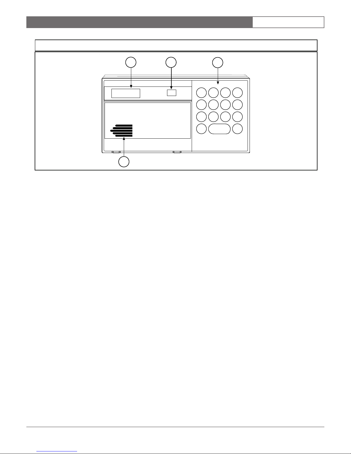
Figure 1: D223TD Keypad
1.0 Description
EN | 2
1
ALL ON
SYSTEM OK
2
On
3
23
1
456
789
CLEAR
0
4
1 - English text display 3 - Function keys
2 - Status indicator 4 - Sounder
1.0 Description
The D223TD Keypad (see Figure 1) is a low-profile,
surface-mount, three-wire unit for use with the Bosch
Security Systems D2212 Control Panel. Features of the
D223TD include:
• Backlit, two-line, liquid crystal display (LCD)
• Status indicator
• Illuminated keypad with function keys, including
three programmable emergency keys
• Built-in sounder that emits several distinct tones
The D2212 Control Panel uses a simple three-wire
connection to supply all power and data requirements
for the D223TD Keypad. Depending on the control
panel’s available auxiliary power, you can install a
maximum of eight keypads in one system.
You can program custom text locally using either the
D5200 Programmer or keypad programming. If using
the D5200, lock down the control panel’s standby pin
before connecting the programmer. You can also
program text remotely using the D5300 Remote
Control Account Manager II (RAM II) or Remote
Programming Software (RPS).
1.1 Display
The D223TD continuously displays the latest status
conditions of the security system. Once the program is
received, it takes 15 seconds for the new text to replace
the old text. When a series of events affecting the system
occurs, the D223TD displays each event by priority. For
example, alarms display before point faults.
Normally, the LCD is always backlit. You can choose to
make it light only after a key is pressed. If you select
this option, the display and backlights extinguish after
approximately 20 seconds. Press and hold the [CLEAR]
key for 5 seconds to turn this feature on or off.
1.2 Keys
The D223TD Keypad contains:
• One [CLEAR] key
• One [ * ] key
• Three emergency keys labeled [A], [B], and [C]
• Number keys [0] to [9]
Use these keys to enter functions and personal passcodes
into the control panel.
A
B
C
*
Bosch Security Systems | 12/03 | 74-07491-000-B
1.3 Response Tones
The keypad sounder annunciates several system
conditions. You can disable the sounder if you choose.
D223TD | Installation Instructions |
Insulate all exposed splices with tape so
they do not short to one another.
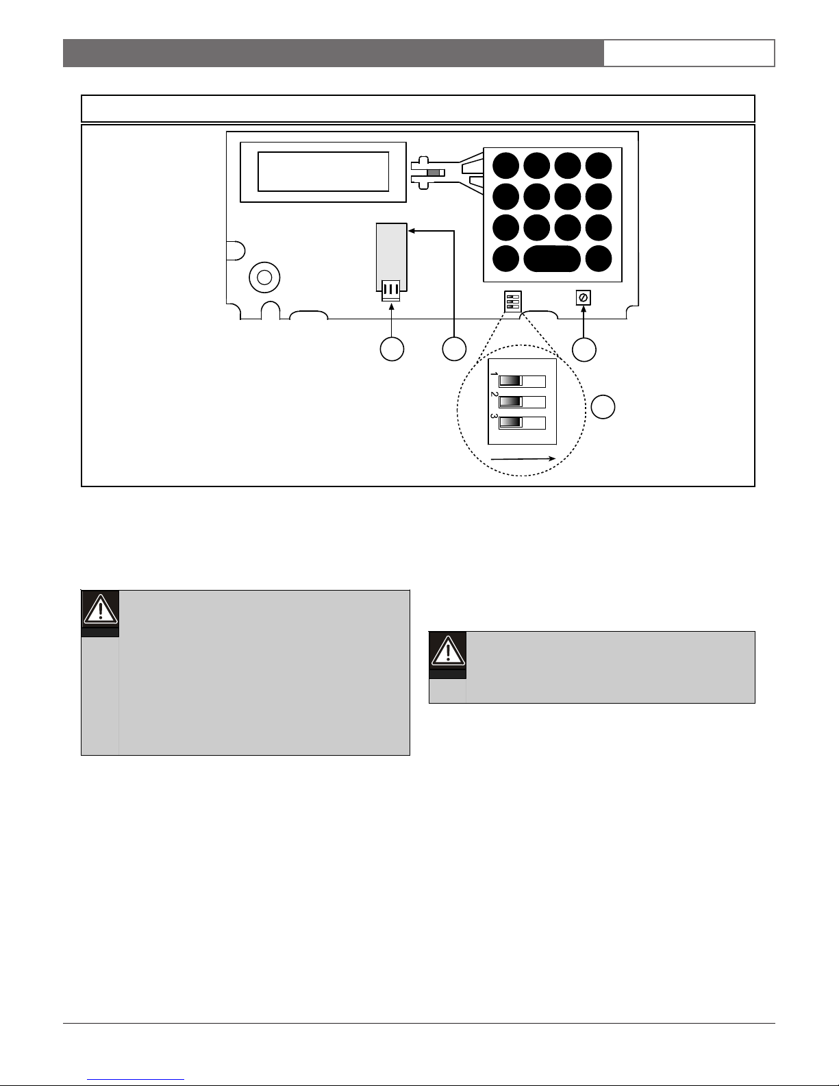
Figure 2: Inside the D223TD
2.0 Installation
1
23
EN | 3
A
456
789
CLEAR
0
1
1 - Data wire connector (J1) 3 - Display adjustment potentiometer (R50)
2 - Wire opening 4 - S1 DIP switch
2
ON
B
C
*
3
4
2.0 Installation
1. Select a mounting location.
Do not place the D222TD Keypad in areas
of extreme cold such as uninsulated
buildings, refrigerated areas, outdoors, or
areas where the temperature can drop below
0°C (+32°F).
3. Splice the connectors to the wires.
Connect the three-wire cable to the control panel.
Use solder to splice the connectors to the wires.
Do not mount the D222TD in locations
exposed to direct sunlight. Direct sunlight
makes the display less visible and can
damage the keypad’s components.
Mount the D223TD on a flat wall, or on the
following Bosch Security Systems accessories:
• D54B Brass Flush Mount Kit
• D54C Chrome Flush Mount Kit
• D55 Command Center Desk Stand
• D56 Command Center Conduit Box
2. Route the wire to the keypad location.
See the control panel’s Installation Guide for
information about the maximum length of keypad
cables and wire resistance. Route data wire away
from electrical, telephone, and other data wiring.
Bosch Security Systems | 12/03 | 74-07491-000-B
4. Remove the front cover from the enclosure base.
Using a small flat-bladed screwdriver, gently push
back the two bottom cover tabs. As you push back
the tabs, lift the bottom of the cover away from the
base and remove the cover.
5. Connect the keypad.
Plug the data wire into the serial data wiring
connector (J1) in the keypad (see Figure 2).
6. Mount the enclosure base.
While pushing excess keypad wire back into the
wall or gang box, place the enclosure base on the
wall in the desired location. Use a center punch or a
pencil to mark the locations of the mounting holes.
Mount the enclosure base to a recessed single-gang
wall box. Secure the enclosure base to the wall or
the gang box.
 Loading...