

Bosch D222TD Installation Instructions Manual
D222TD
Installation Instructions
EN
Keypad
D222TD | Installation Instructions |
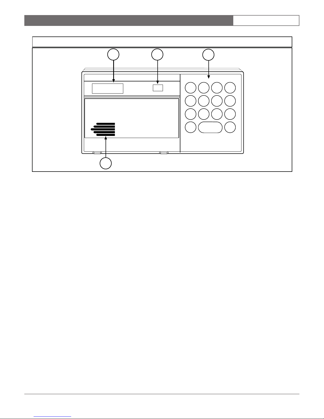
Figure 1: D222TD Keypad
1.0 Description
EN | 2
1
ALL ON
SYSTEM OK
2
1
On
3
23
456
789
CLEAR
0
4
1 - English text display 3 - Function keys
2 - Status indicator 4 - Sounder
1.0 Description
The D222TD Keypad (see Figure 1) is a low-profile,
surface-mount, three-wire unit with four hard-wired
expansion points for use with the Bosch Security
Systems D2212 Control Panel. Features of the D222TD
include:
• Backlit, two-line liquid crystal display (LCD)
• Status indicator
• Illuminated keypad with function keys, including
three programmable emergency keys
• Built-in sounder that emits several distinct tones
The D2212 Control Panel uses a simple three-wire
connection to supply all power and data requirements
for the D222TD Keypad. Depending on the control
panel’s available auxiliary power, you can install a
maximum of eight keypads in one system.
You can program custom text locally using either the
D5200 Programmer or keypad programming. If using
the D5200, lock down the control panel’s standby pin
before connecting the programmer. You can also
program text remotely using the D5300 Remote
Account Manager II (RAM II) or Remote Programming
Software (RPS).
1.1 Display
The D222TD continuously displays the latest status
conditions of the security system. Once the program is
received, it takes 15 seconds for the new text to replace
the old text. When a series of events affecting the system
occurs, the D222TD displays each event by priority. For
example, alarms display before point faults.
Normally, the LCD is always backlit. You can choose to
make it light only after a key is pressed. If you select
this option, the display and backlights extinguish after
approximately 18 seconds. Press and hold the [CLEAR]
key for 5 seconds to turn this feature on or off.
1.2 Keys
The D222TD Keypad contains:
• One [CLEAR] key
• One [ * ] key
• Three emergency keys labeled [A], [B], and [C]
• Number keys [0] to [9]
Use these keys to enter functions and personal passcodes
into the control panel.
A
B
C
*
Bosch Security Systems | 12/03 | 74-07391-000-B
1.3 Response Tones
The keypad sounder annunciates several system
conditions. You can disable the sounder if you choose.
D222TD | Installation Instructions |
Do not place the D222TD Keypad in areas
of extreme cold such as uninsulated
buildings, refrigerated areas, outdoors, or
areas where the temperature can drop below
0°C (+32°F).
Do not mount the D222TD in locations
exposed to direct sunlight. Direct sunlight
makes the display less visible and can
damage the keypad’s components.
Route wire runs away from electrical,
telephone, and other data wiring.
2.0 Wiring the D222TD Protective Points
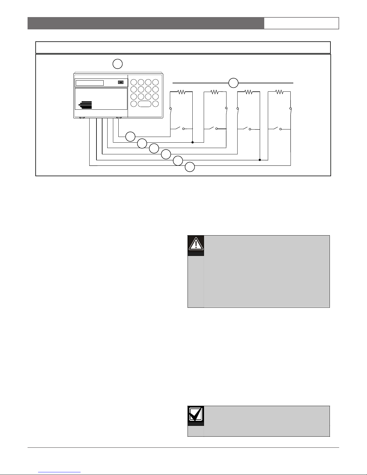
Figure 2: Wiring the D222TD Protective Points
1
EN | 3
ALL ON
SYSTEM OK
On
23
1
456
789
CLEAR
0
3
4
A
B
C
*
5
ABCD
6
4
7
1 - D222TD Keypad 5 - Point B (orange wire)
2 - 1 kΩ EOL resistors 6 - Point C (yellow wire)
3 - Point A (blue wire) 7 - Point D (white wire)
4 - Common (black wire)
2.0 Wiring D222TD Points
The D222TD Keypad expands the system with four
3.0 Installation
1. Select a mounting location.
hard-wired protective point inputs, Points A, B, C, and D
(see Figure 2). Each point functions independently and
does not interfere with the operation of the others.
Each point is supervised with a D105BL 1 kΩ, an end-ofline (EOL) resistor. (Four D105BLs are supplied with the
unit.) Connect the dry contact sensing devices in series
(normally closed [NC]) or in parallel (normally open
[NO]) to any of these points. Each point can detect open
circuit, closed circuit, and normal circuit conditions.
Program the control panel with a point code for each
protective point. The point codes determine how each
point responds to faults and keypads.
Refer to the Point Codes in the D2212 Program Entry Guide
(P/N: 74-07386-000) for programming details.
Mount the D222TD on a flat wall, or on the
following Bosch Security Systems accessories:
• D54B Brass Flush Mount Kit
• D54C Chrome Flush Mount Kit
• D55 Command Center Desk Stand
• D56 Command Center Conduit Box
2. Route the point expansion wire.
Route the wire from the points of protection to the
location where you will mount the keypad. See the
control panel’s Installation Guide for information on
the maximum length of point cables and wire
resistance.
2
Bosch Security Systems | 12/03 | 74-07391-000-B
 Loading...