

Bosch D220ATD Installation Instructions Manual
Keypad D220ATD
Installation Instructions
1.0 Description
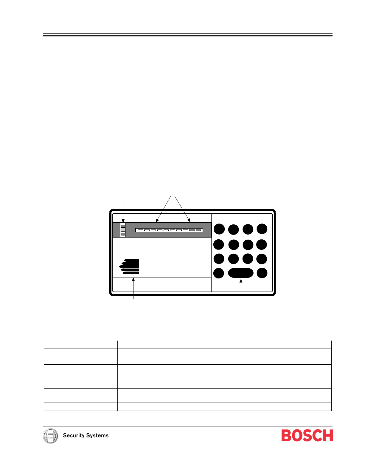
The D220ATD Keypad (see Figure 1) is a low-profile, surface-mount, three-wire unit designed for use with the Bosch Security
Systems D2112, D2112E, and D2212 Control/Communicators. The D220ATD features an illuminated keypad, LED display,
three programmable emergency keys, and built-in sounder that emits several distinct tones.
The control/communicator supplies all power and data requirements for the D220ATD using a simple three-wire connection.
1.1 Display
The D220ATD Keypad uses LEDs to display system status. When events occur that affect points, the D220ATD illuminates
the LED corresponding to the point number.
1.2 Keys
The D220ATD Keypad has a [CLEAR] key, three emergency keys (labeled A, B, and C), and number keys from zero to nine.
These keys are used to enter functions and personal passcodes into the panel. The [*] key is not used.
1.3 Response Tones
The D220ATD Keypad uses a sounder to annunciate system conditions. You can disable the sounder if you choose.
System Status Lights
2.0 Specifications
Operating Voltage
Current Requirements
Enclosure Dimensions
(H x W x D)
Operating Temperature
Non-condensing Relative
Humidity
Command Center Wiring
Point Status
ALL
PART
OK
1 2 3 4 5 6 7 8
Sounder
ON NO DELAY
1
4
7
0
3
2
5
6
9
8
CLEAR
Function Keys
A
B
C
*
Figure 1: D220ATD Keypad
Nominal 12 VDC supplied by the Control/Communicator auxiliary power supply.
Maximum: 125 mA keypad backlights on, LCD on, LED on, tone on
Standby: 30 mA backlight off
4.56 in. x 8.15 in. x 0.816 in. (11.6 cm x 20.7 cm x 21 mm)
+32°F to+122°F (0°C to +50°C)
5% to 85% at +86°F (+30°C)
Three-wire cable supplies data and power

D220ATD
Installation
3.0 Installation
To install the D220ATD Keypad:
1. Select a mounting location.
Do not locate the D220ATD in areas of extreme cold, such as an uninsulated building, refrigerated areas,
outdoors, or in areas where the temperature can drop below +32°F. Do not mount the keypad in a location
exposed to direct sunlight that makes the display less visible and can also damage keypad components.
Mount the D220ATD on a flat wall or on the following Bosch Security Systems accessories:
• D54B Brass Flush Mount Kit
• D54C Chrome Flush Mount Kit
• D55 Command Center Desk Stand
• D56 Command Center Conduit Box
2. Route the keypad cable to the location where you mount the keypad.
Refer to the panel’s Installation Guide for information on the maximum length of keypad cables and wire
resistance. Be sure to route data wire runs away from electrical, telephone, and other data wiring.
3. Wire the connector.
The three-wire connector attaches to the keypad cable. Use solder to splice the three-wire connector to the
keypad cable. Be sure to insulate all exposed splices with tape so they do not short to one another.
4. Remove the front cover from the enclosure base.
Use a small flat-bladed screwdriver to gently push the two bottom cover-tabs back. As you push back the tabs,
lift the bottom of the cover away from the base and then remove the cover.
• When using the D220ATD with the D2112/D2112E, cut and remove the R30 resistor. See Figure 2 on
page 3.
• If disabling sounder, do so before connecting the keypad to the cable. Disable the sounder by cutting
and removing resistor R22 located in the lower left-hand corner of the board, next to the sounder.
Refer to Figure 2 on page 3.
• Fire Points need the trouble sounder. Disable the sounder (by removing R22) stops the D220ATD
from annunciating fire point trouble. If fire points are installed as part of this system, contact the
local AHJ to verify code requirements for fire trouble sounders before disabling the D220ATD
sounder.
• Enable sounder for UL systems. For UL installations, the sounder on at least one keypad must
remain connected.
5. Connect the keypad.
Route the three color-coded flying leads through the opening in the back of the enclosure base and plug into
the serial data wiring connector (J1) in the keypad (see Figure 2).
6. Mount the enclosure base.
While pushing excess keypad wire back into the wall or gang box, place the enclosure base on the wall in the
desired location. Use a center punch or a pencil to mark the locations of the mounting holes.
If desired, mount the enclosure base to a recessed single-gang wall box. Two mounting screw holes on the base
are positioned for standard single-gang compatibility. Secure the enclosure base to the wall or gang box.
7. Replace the front cover.
Align the top two tabs of the enclosure cover with the top two tab slots in the enclosure base. Slide the top of
the cover into the base. Gently push the bottom of the cover down on the base until it snaps into place.
D220ATD Installation Instructions
Page 2 © 2003 Bosch Security Systems74-07104-000-D
 Loading...