

Page 1
AE203R/D203 Enclosure
Installation Instructions
1.0 Description
The AE203R/D203 Enclosure houses many Bosch
Security Systems peripheral modules and fire digital
alarm communicator transmitters (DACTs). It is also
compatible with an enclosure tamper switch.
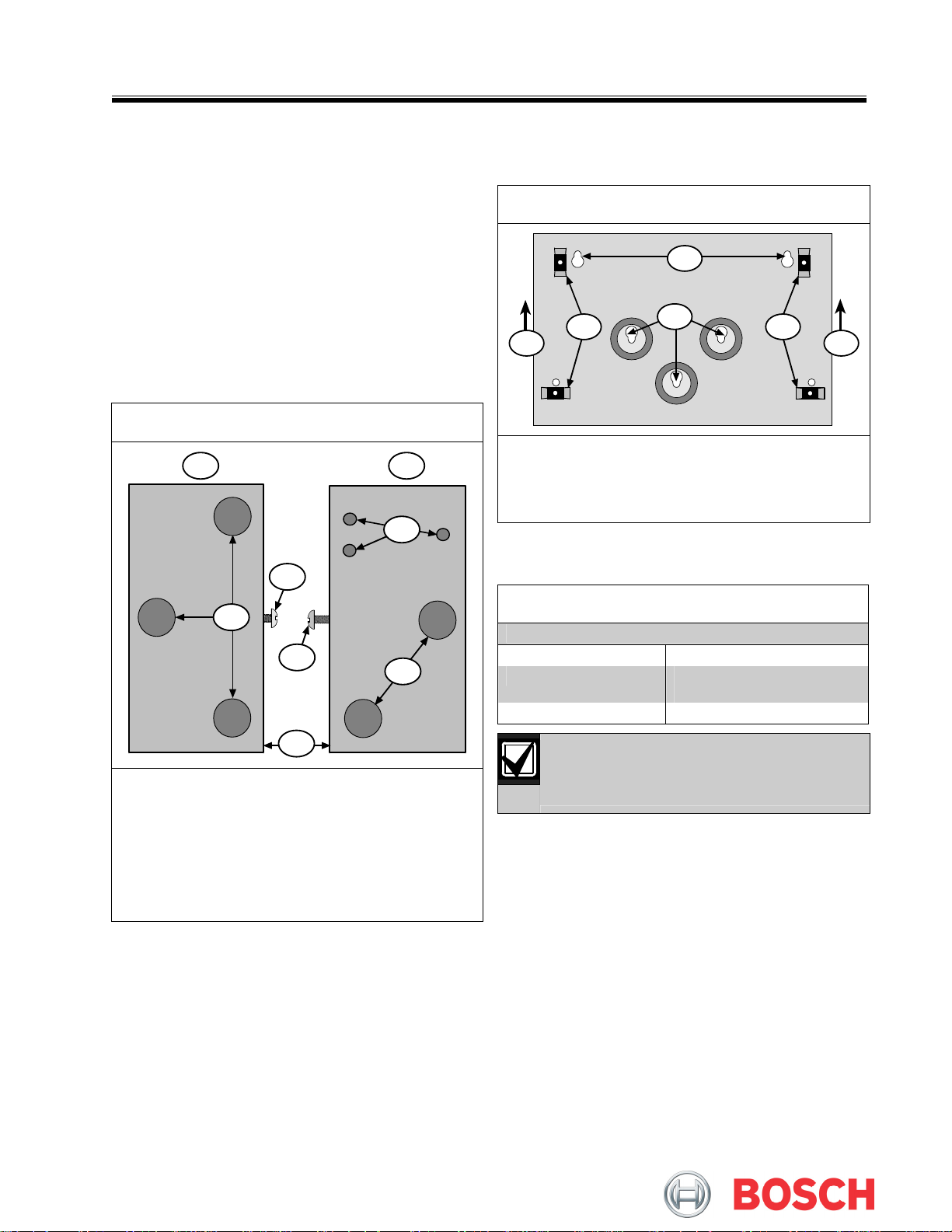
Figure 2: Mounting
2
2.0 Installation
1. Remove the desired wire knockouts in the
enclosure and install the D110 Tamper Switch if
required (Figure 1).
Figure 1: Wire Knockout Locations
1 2
3
7
4
6
5
1 - Left exterior
2 - Right exterior
3 - Tamper switch holes (3)
4 - Wire knockouts (5)
5 - Front
6 - Machine screw
7 - Self-tapping screw
2. Ensure the enclosure in the position shown in
Item 1 of Figure 2.
3. Using the mounting holes (Item 2 in Figure 2),
attach the AE203R to the wall.
4. Mount the module or listed fire DACT to the
enclosure using the supplied three-hole mounting
pattern or mounting clips.
4
3 3
4
1 - Position the enclosure with this end up.
2 - Mounting holes (2)
3 - Enclosure lances (4)
4 - Mounting holes (3)
3.0 Specifications
Table 1: Specifications
Dimensions (H x W x D)
Color
Tamper Switch
Refer to the control panel literature or
specific module literature for instructions on
connecting to other devices.
5 in. x 2.5 in. (37 cm x 32 cm)
AE203R (red)
D203 (grey)
D110
11
Page 2

© 2006 Bosch Security Systems, Inc.
130 Perinton Parkway, Fairport, NY 14450-9199 USA
Customer Service: (800) 289-0096; Technical Support: (888) 886-6189
F01U012076B
Installation Instructions
11/06
AE203R/D203
Page 2 of 2
 Loading...