

Page 1
Low Battery Disconnect Module D135A
Installation Instructions
1.0 Description
The D135A Low Battery Disconnect Module is only used with the D4112 and D6112 Control/Communicators to protect the
battery from deep discharge in the event of an extended AC power outage. D135A disconnects the contol/communicator
from the battery when the battery level drops to 9.5 VDC.
2.0 Installation
Follow steps 1 through 3 below and step 4 on page 2.
Observe polarity when connecting the D135 module.
1. Plug in the transformer to supply the control/communicator with AC power.
Note: When using the D135A, the control panel will not boot up on battery power. The panel must be supplied AC power
for initial power up.
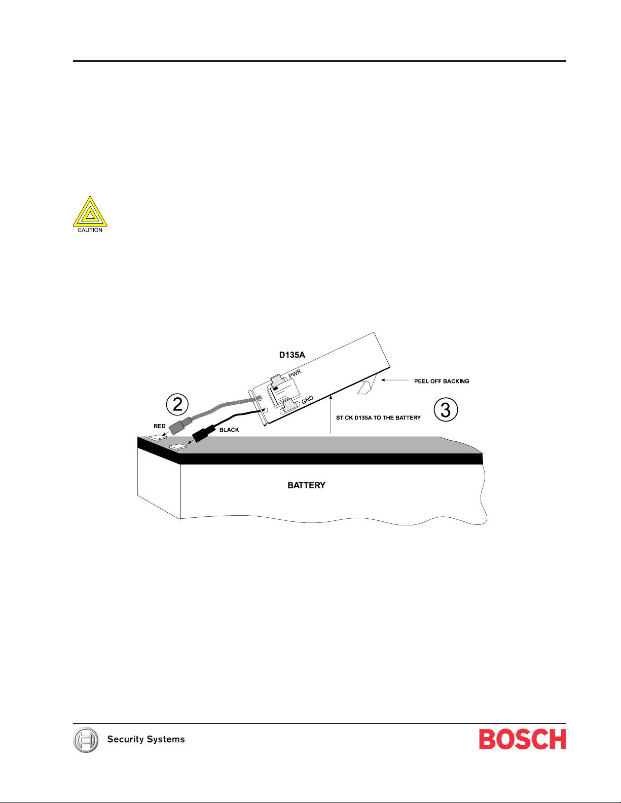
2. Insert the black lead from the D135A onto the black (-) battery terminal. Insert the red lead from the D135A
onto the red (+) battery terminal.
3. Peel off the protective backing from the D135A. Stick the D135A to the top of the battery.
Page 2
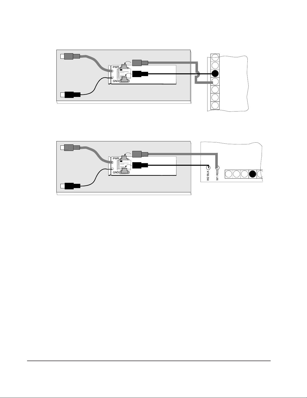
4a. D6112 Control/Communicator: Using the D6112 battery leads, connect the D6112 terminal 3 to the D135A.
+
RED
BLACK
-
4b. D4112 Control Communicator: Using the D4112 battery leads, connect the black battery lead to the D135A
GND (ground) terminal, and connect the red battery lead to the D135A PWR (power) terminal.
BATTERY
RED
BLACK
D135A
1
2
EARTH GROUND
3
&BatteryNegative
BATTERY POSITIVE ONLY
4
5
6
6
D4112
D6112
+
RED
BLACK
BATTERY
RED
BLACK
D135A
213
4
-
5
© 2002 Bosch Security Systems 74-06499-000-D 11/02
130 Perinton Parkway, Fairport, NY 14450-9199 USA Installation Instructions D135A
Customer Service: (800) 538-5807; Technical Support (888) 886-6189 Page 2 of 2
 Loading...