

Smoke Detector Reversing Relay Module
D132A
en Installation Instructions

!
Smoke Detector Reversing Relay
Module
Notices | en 3
1
Notices
These instructions cover the installation of the D132A Smoke Detector Reversing Relay
Module in a household fire system supervised by a fire alarm control panel (FACP) or a
combination Burglary/Fire control panel.
Before installing the module, become familiar with the Installation and Operation Guide for the
control panel you are using.
Install, test and maintain the module according to these instructions, NFPA 72, local codes,
and the authority having jurisdiction (AHJ). Failure to follow these instructions can result in
failure of a detector to initiate an alarm event. Bosch Security Systems, Inc. is not responsible
for improperly installed, tested or maintained devices.
Warning!
Follow these instructions to avoid personal injury and damage to equipment.
NFPA 72 requires that you perform a complete system wide functional test following any
modifications, repair, upgrades or adjustments made to the system’s components, hardware,
wiring, programming and software/firmware.
Bosch Security Systems, Inc. Installation Instructions 2013.08 | 06 | F.01U.069.463
4 en | Notices
Smoke Detector Reversing Relay
Module
2
Description
This module allows compatible control panels (see the table below) to sound all smoke
detectors connected to point 1 or zone 1 when a single smoke detector on the loop goes into
alarm. To restore the smoke detectors to normal, reset the smoke detectors.
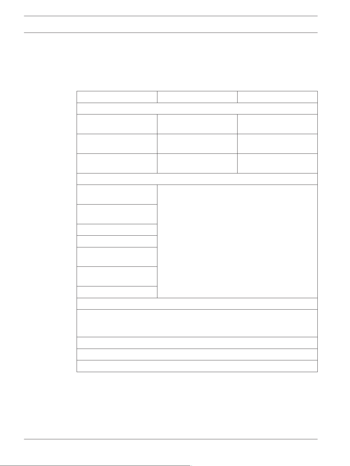
The following table lists control panels compatible with the D132A:
Control panels Compatible relays See section:
Active:
B Series panels
D6412 and D4412 panels** Wiring to a D6412 or D4412
G Series (GV2 and higher)
2
panels
Legacy:
G Series (prior to GV2)
3
panels
D9412, D7412, D7212**
panels
1 **
D275, PAM-4 Wiring to a B Series panel,
page 7
panel, page 12
D275, PAM-4 Wiring to a G Series panel,
page 13
See control panel’s documentation on the Bosch website
(http://www.boschsecurity.com)
ICP-EZM2
D2812 panel**
D2412U and D2412UE
panels**
D2212, D2212B, and
D2212BE panels**
DS7240 and DS7220 panels**
1
B Series panels = B5512**, B4512**, and B3512**
2
G Series (GV2 and higher) panels = GV4 (D9412GV4, D7412GV4, and D7212GV4**), GV3
(D9412GV3, D7412GV3, and D7212GV3**), and GV2 (D9412GV2, D7412GV2, and
D7212GV2**)
3
G Series (prior to GV2) panels = D9412G, D7412G, D7212G**
* Legacy products were investigated to comply only to UL864 8th edition
** indicates products which are not UL listed for commercial fire applications
2013.08 | 06 | F.01U.069.463 Installation Instructions Bosch Security Systems, Inc.
Smoke Detector Reversing Relay
Module
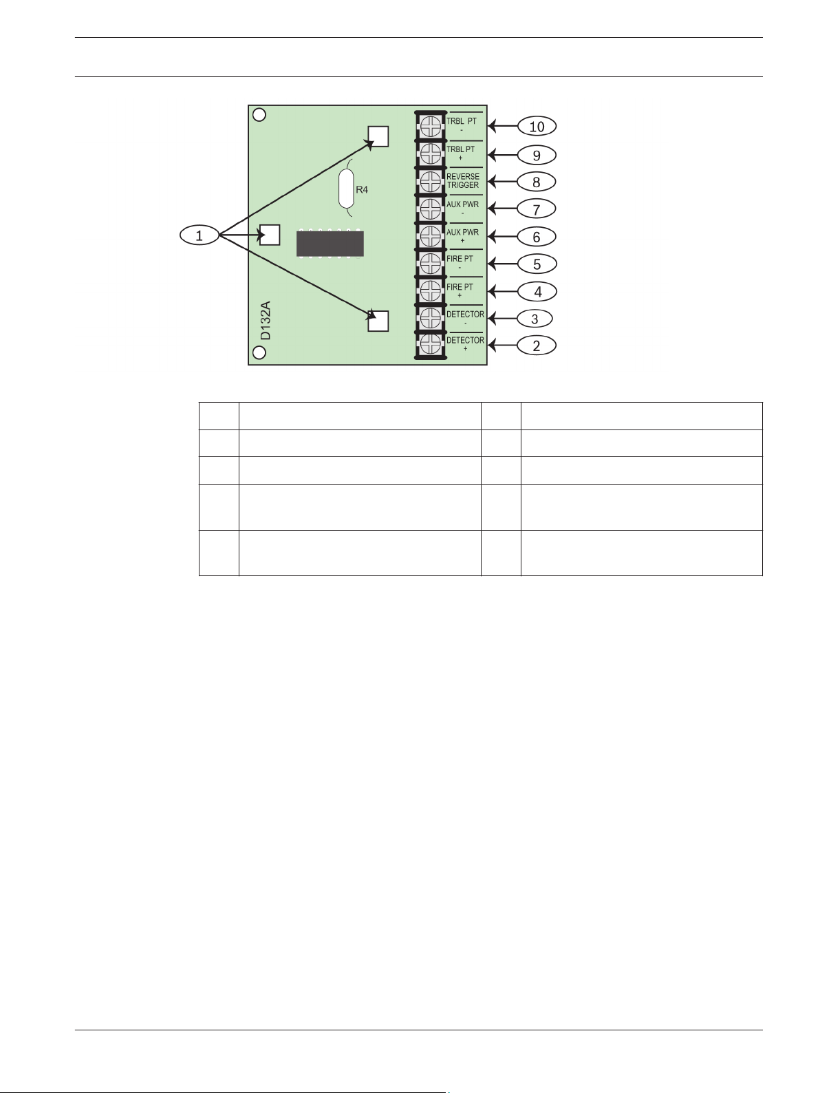
Figure 2.1: D132A smoke detector reversing relay module
1 Mounting holes 6 Positive (+) power for module
2 Positive (+) to detector 7 Negative (-) power for module
Notices | en 5
3
3 Negative (-) to detector 8 Trigger to reverse rdetector power
4 Powered loop from control panel or
9 Positive (+) to trouble point
D125B
5 Powered loop from control panel or
10 Negative (-) to trouble point
D125B
Installation
1. Align the module with an available three-hole module mounting location in the enclosure.
2. Fasten the module to the enclosure with the three supplied screws.
For mounting locations inside the enclosure, see the control panel’s Installation Instructions.
Bosch Security Systems, Inc. Installation Instructions 2013.08 | 06 | F.01U.069.463
6 en | Notices
Smoke Detector Reversing Relay
Module
4
Wiring
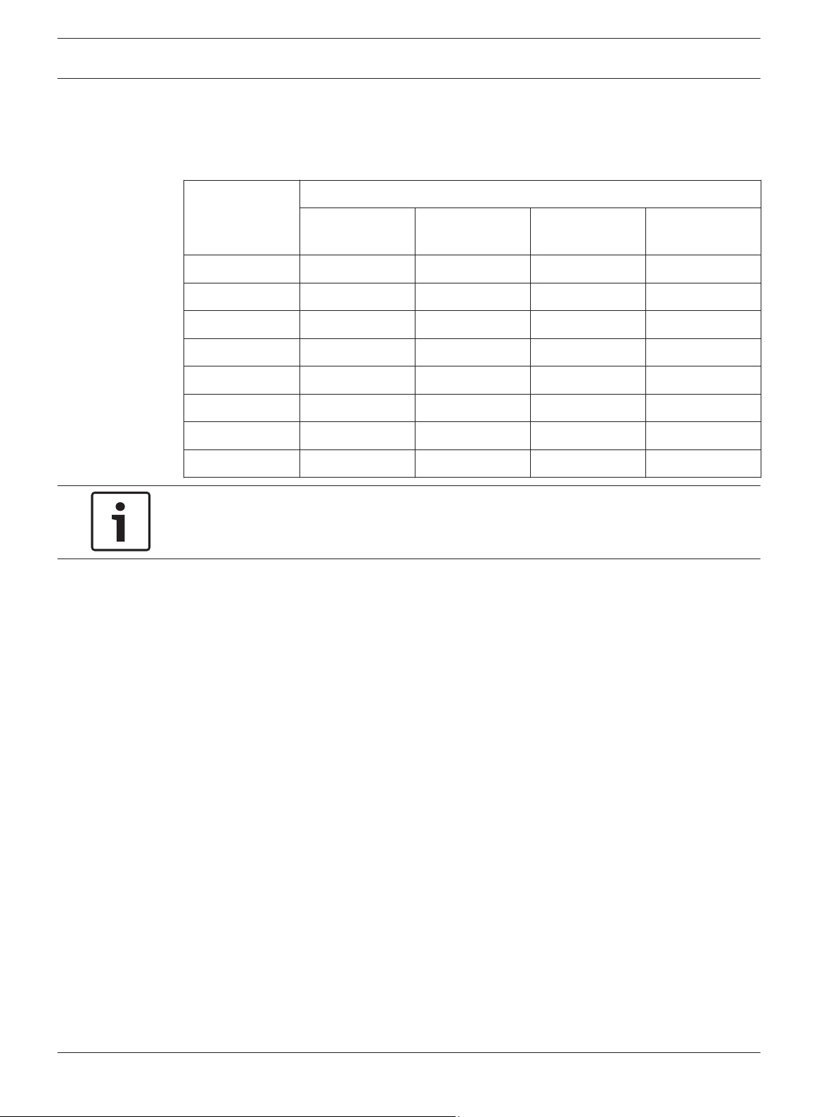
Use the table below to ensure you are using the proper wire gauge for the number of
detectors used and for the length of the detector circuit:
Number of
detectors
22 AWG
(0.34 mm2)
1 935 ft (285 m) 1490 ft (454 m) 2370 ft (722 m) 3770 ft (1149 m)
2 935 ft (285 m) 1490 ft (454 m) 2370 ft (722 m) 3770 ft (1149 m)
3 465 ft (142 m) 745 ft (227 m) 1185 ft (722 m) 1885 ft (575 m)
4 310 ft (95 m) 495 ft (150 m) 790 ft (241 m) 1255 ft (383 m)
5 230 ft (70 m) 370 ft (113 m) 590 ft (180 m) 940 ft (287 m)
6 185 ft (56 m) 295 ft (90 m) 470 ft (143 m) 750 ft (229 m)
7 155 ft (47 m) 245 ft (75 m) 395 ft (120 m) 625 ft (191 m)
8 130 ft (40 m) 210 ft (64 m) 335 ft (103 m) 535 ft (163 m)
Notice!
To ensure system supervision, do not use looped wire under the terminals. Break the run to
provide supervision of the connections.
An external 12 VDC or 24 VDC power supply listed for fire signaling units and commercial or
residential burglary units can be used.
The external power supply must be UL1481 or UL864 Listed, regulated, and power‑limited.
Install the control panel and external power supply in the same room no more than 20 ft (6 m)
apart. The interconnecting wires between the control panel and external power supply must
be in conduit.
The power source for both the auxiliary power supply and the control panel must be from the
same dedicated AC branch circuit.
Maximum detector circuit length
20 AWG
(0.5 mm2)
18 AWG
(0.75 mm2)
16 AWG
(1.5 mm2)
2013.08 | 06 | F.01U.069.463 Installation Instructions Bosch Security Systems, Inc.
Smoke Detector Reversing Relay
Module
Notices | en 7
4.1
4.1.1
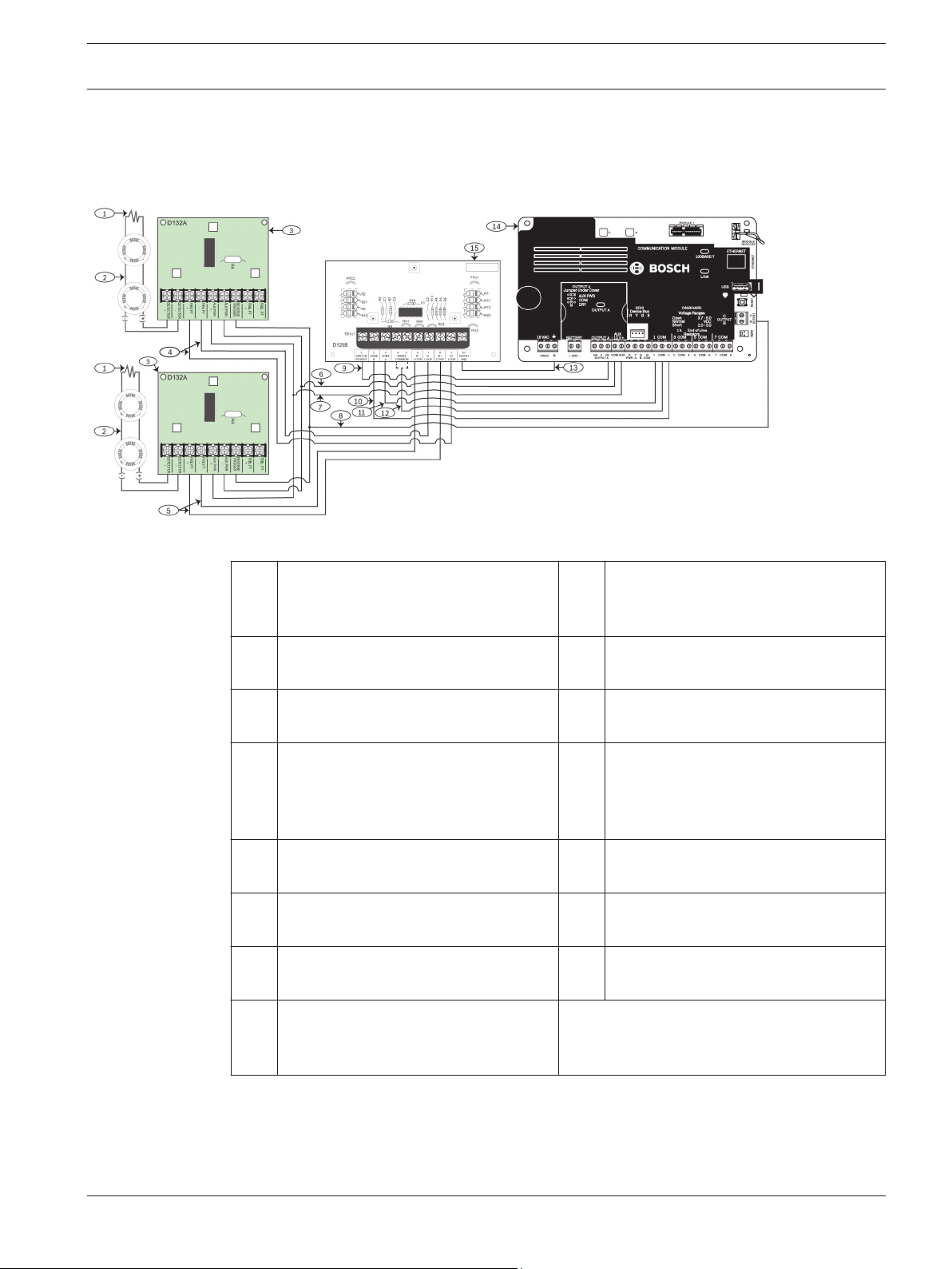
Figure 4.1: Two-wire wiring of D132A modules to a B Series control panel for power supplied by the panel
Wiring to a B Series panel
Two-wire wiring for 12 VDC supplied by the control panel
1 Detector loop (2‑wire) 9 Connection from D125B switch power
to control panel’s A output relay (NC).
Set the Output A jumper for AUX PWR.
2 EOL resistor 10 Connection for D125B Zone B to an
on-board point on the control panel
3 D132A module 11 Connection for D125B Zone A to an
on‑board point on the control panel
4 Connections for one D132A fire point
to D125B A loop
12 Connection from D125B Common
(either 4 or 5) to the control panel’s
common for the on‑board points
connected
5 Connections for the other D132A fire
13 Earth Ground
point to D125B B loop
6 Connection for AUX PWR - from D132A
14 B Series control panel
modules to B-series panel COM
7 Connection for AUX PWR + from
15 D125B module
D132A modules to B-series panel AUX
8 Connection from reverse trigger on
D132A modules to control panel B or C
output
Bosch Security Systems, Inc. Installation Instructions 2013.08 | 06 | F.01U.069.463

8 en | Notices
Smoke Detector Reversing Relay
Module
Notice!
The illustration shows the D132A modules wired for both detector loops triggered by the
same output. For loops triggered by separate outputs, connect one D132A module reverse
trigger to B output and the other D132A revese trigger to C output.
2013.08 | 06 | F.01U.069.463 Installation Instructions Bosch Security Systems, Inc.
 Loading...