

Bosch CE SPLIT Installation And Maintenance Manual
Installation and Maintenance Manual
CE Split
Series
6 720 220 049
Revised 03-11

©Copyright 2011 Bosch, Inc All rights reserved
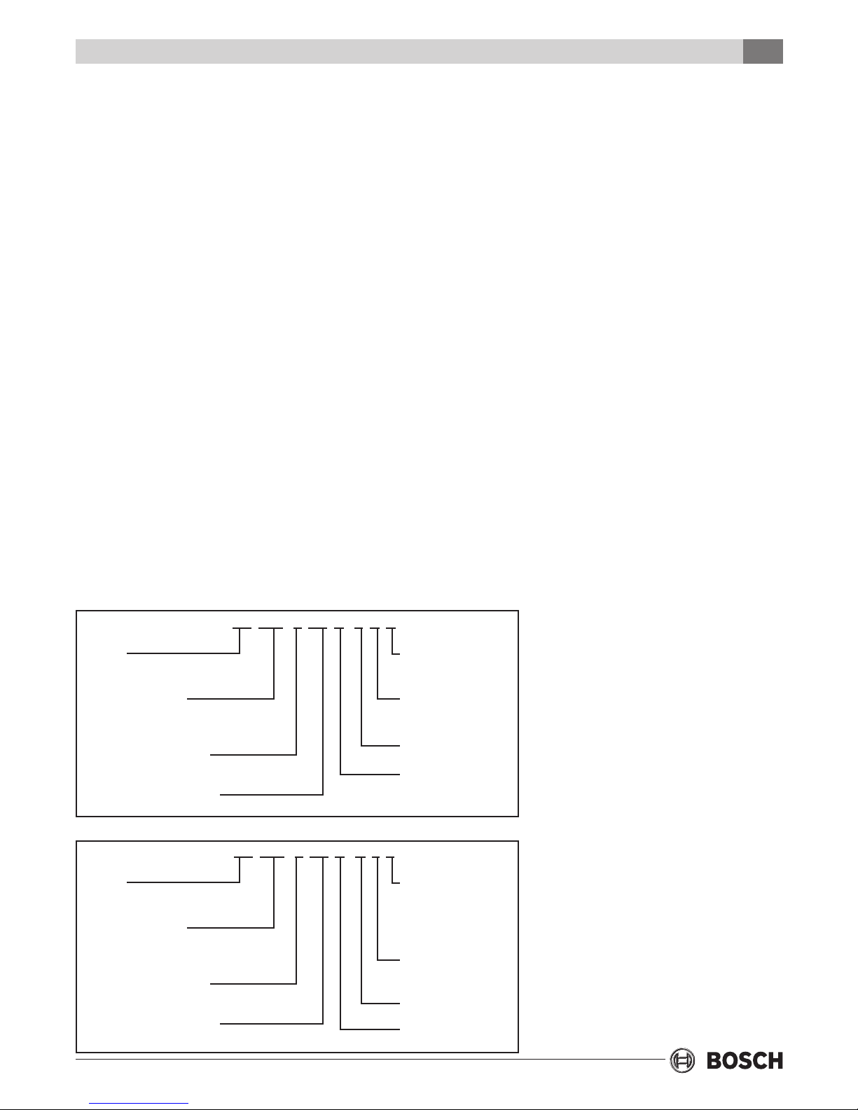
Table of Contents
TABLE OF CONTENTS
Model Nomenclature .................................................................................... 3
Initial Inspection .......................................................................................... 4
General Description ..................................................................................... 4
Moving and Storage ..................................................................................... 4
Safety Considerations .................................................................................. 4
Location ....................................................................................................... 4
Installation ................................................................................................... 5
Condensate Drain ........................................................................................ 6
Duct System ................................................................................................. 6
Electrical ...................................................................................................... 7
Electric Heater Package Option ................................................................... 7
Thermostat Connections ............................................................................. 9
Safety Devices & the UPM Controller ......................................................... 10
Sequence of Operation Two-Stage Units .................................................... 11
Piping ........................................................................................................ 12
Well Water Systems .................................................................................... 15
Cooling Tower / Boiler Application ............................................................. 15
Earth Coupled Systems .............................................................................. 16
System Checkout ....................................................................................... 16
Unit Start-Up .............................................................................................. 16
Heat Recovery Package .............................................................................. 16
Maintenance .............................................................................................. 18
Unit Specications ..................................................................................... 19
Wiring Diagrams ......................................................................................... 20
Two Stage Multi-Step - Single Phase - Air Handler .................................. 20
Two Stage - Single Phase - Condensing Section ..................................... 21
Operating Pressures & Temperatures ........................................................ 22
Unit Check Out ........................................................................................... 26
Trouble Shooting ........................................................................................ 27
CE Split Series
3
MODEL NOMENCLATURE
Condensing Section
CE 049 - 1 CS C - F X X
SERIES:
CE
NOMINAL CAPACITY:
(049 = 49,000 BTUH)
025, 035, 049, 061,
071 AVAILABLE
VOLTAGE DESIGNATIONS:
1-208-230/1/60
CABINET CONFIGURATION:
CS-CONDENSING SECTION
Air Handler
CE 049 - 1 AV X - X L T
SERIES:
CE
NOMINAL CAPACITY:
(049 = 49,000 BTUH)
025, 035, 049, 061,
071 AVAILABLE
VOLTAGE DESIGNATIONS:
1-208-230/1/60
CABINET CONFIGURATION:
AV-VERTICAL AIR HANDLER
AH-HORIZONTAL AIR HANDLER
NOT USED FOR
CONDENSING
SECTIONS
NOT USED FOR
CONDENSING
SECTIONS
WATER CONNECTION
F-FRONT
HEAT EXCHANGER
MATERIAL
C-COPPER
N-CUPRO NICKEL
SUPPLY AIR LOCATION:
T - VT TOP
S-HZ STRAIGHT THRU
E-HZ END BLOW
RETURN AIR LOCATION
L-LEFT
R-RIGHT
NOT USED FOR AIR
HANDLERS
NOT USED FOR AIR
HANDLERS
Revised 03-11 Subject to change without prior notice
6 720 220 049
Initial Inspection
4
CE Split Series
INITIAL INSPECTION
Be certain to inspect all cartons or crates on each
unit as received at the job site before signing the
freight bill. Verify that all items have been received
and that there are no visible damages; note any
shortages or damages on all copies of the freight bill.
In the event of damage or shortage, remember that
the purchaser is responsible for ling the necessary
claims with the carrier. Concealed damages not
discovered until after removing the units from the
packaging must be reported to the carrier within 24
hours of receipt.
GENERAL DESCRIPTION
These Split System Heat Pumps provide the best
combination of performance and efciency
available. Safety devices are built into each unit to
provide the maximum system protection possible
when properly installed and maintained.
The CE Split Water-to-Air Heat Pumps are
Underwriters Laboratories (UL) and (cUL) listed for
safety. The Water-to- Air Heat Pumps are designed to
operate with entering uid temperature between
20°F to 80°F in the heating mode and between 50°F
to 110°F in the cooling mode. Efciencies and
capacities will vary as entering uid and return air
temperatures vary.
required, stack units as follows: Vertical units no
more than two high. Horizontal units no more than
three high.
SAFETY CONSIDERATIONS
Installation and servicing of this equipment can be
hazardous due to system pressure and electrical
components. Only trained and qualied personnel
should install, repair, or service the equipment.
Untrained personnel can perform basic functions of
maintenance such as cleaning coils and replacing
lters.
Before performing service or maintenance
operations on the system, turn off main power
to the unit. Electrical shock could cause
personal injury or death.
When working on equipment, always observe
precautions described in the literature, tags, and
labels attached to the unit. Follow all safety codes.
Wear safety glasses and work gloves. Use a
quenching cloth for brazing, and place a re
extinguisher close to the work area.
The air handler blower should only be operated
when a duct is installed and secured to heat pump
duct collar in order to avoid possible injury.
LOCATION
50°F Min. EWT for well water applications with
sufcient water ow to prevent freezing.
Antifreeze solution is required for all closed
loop applications where the uid temperature
may drop below 50°F. Cooling Tower/Boiler
and Earth Coupled (Geo Thermal)
applications should have sufcient antifreeze
solution to protect against extreme conditions
and equipment failure. Frozen water coils are
not covered under warranty.
This product should not be used for
temporarily heating/cooling during
construction. Doing so may effect the units
warranty.
MOVING AND STORAGE
If the equipment is not needed for immediate
installation upon its arrival at the job site, it should
be left in its shipping carton and stored in a clean,
dry area. Units must only be stored or moved in the
normal upright position as indicated by the “UP”
arrows on each carton at all times. If unit stacking is
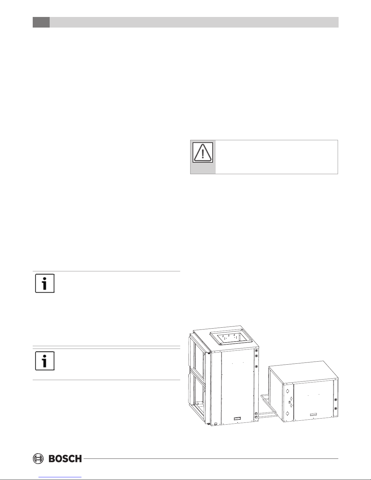
To maximize system performance, efciency and
reliability, and to minimize installation costs, it is
always best to keep the refrigerant lines as short as
possible. Every effort should be made to locate the
air handler and the condensing section as close as
possible to each other.
Figure #1
6 720 220 049
Subject to change without prior notice Revised 03-11
Installation
CE Split Series
5
INSTALLATION
Remove all shipping blocks under blower
housing.
The installer should comply with all local codes
and regulations which govern the installation of
this type of equipment. Local codes and
regulations take precedent over any
recommendations contained in these instructions.
In lieu of local codes, the equipment should be
installed in accordance with the recommendations
made by the National electric code, and in
accordance with the recommendations made by
the National Board of Fire Underwriters. All local
seismic codes for seismic restraint of equipment,
piping, and duct work shall be strictly adhered to.
CONDENSING SECTION
Locate the condensing section in an area that
provides sufcient space to make water and
electrical connections, allowing easy removal of the
access panels. A 36" clearance in front of the unit is
recommended. This will ensure proper work space
for service personnel to perform maintenance or
repair.
AIR HANDLER
Locate the air handler unit in an indoor area that
allows easy removal of the lter and access panels,
and has enough room for service personnel to
perform maintenance or repair. Provide sufcient
room to make electrical and duct connections. A 36"
clearance in front of the unit is recommended. If the
unit is located in a conned space such as a closet,
provisions must be made for return air to freely
enter the space. On horizontal units, allow adequate
room below the unit for a condensate drain trap.
Sufcient space should be provided on the sides to
allow for lter replacement on horizontal air
handlers and in the front for vertical air handlers.
The air handler units are not approved for outdoor
installation; therefore, they must be installed inside
the structure being conditioned.
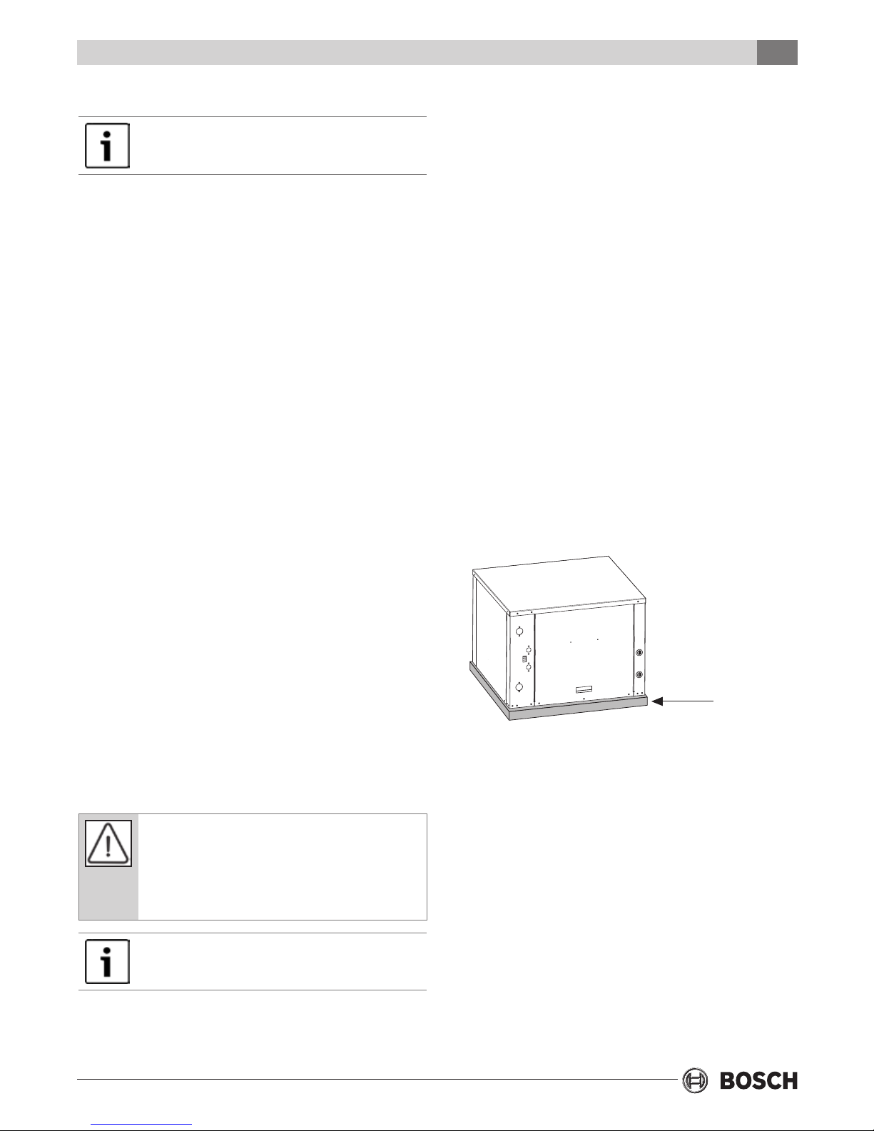
MOUNTING VERTICAL UNITS
Vertical units should bemounted level on a
vibration absorbing pad slightly larger than the
base to minimize vibration transmission to the
building structure. (See Figure #2).
If the condensing section is installed in a location
where ambient temperatures can fall below
freezing, some form of freeze protection should be
employed such as anti-freeze. Where the use of
anti-freeze is not possible for example in a ground
water application the uid circulating pump should
operate continuously to prevent possible condenser
freeze-up and to optimize overall system
performance. Consult the factory in these instances
for guidance.
Water freezes at 32°F. Frozen water coils are not
covered under the limited product warranty. It is
the installer’s responsibility to insure that the
condensing section is installed in a location or has
the proper controls to prevent rupturing the water
coil due to freezing conditions.
Do not remove the protective caps or plugs
from the service valves until the refrigerant
lines are run and ready for nal connection.
VIBRATION
PAD
Figure #2
FULL SIZE
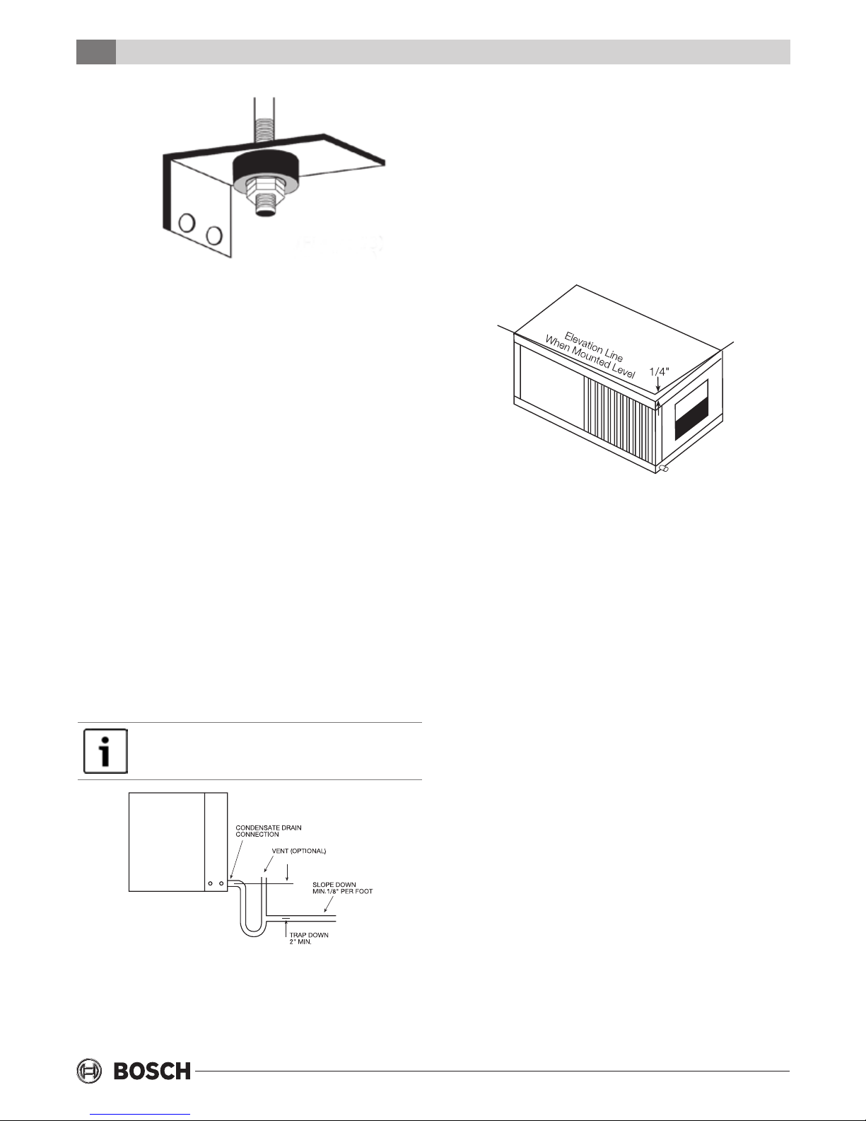
MOUNTING HORIZONTAL UNITS
While horizontal units may be installed on any level
surface strong enough to hold their weight, they
are typically suspended above a ceiling by threaded
rods. The rods are usually attached to the unit
corners by hanger bracket kit. (See Figure #3). The
rods must be securely anchored to the ceiling.
Refer to the hanging bracket assembly and
installation instructions for details. All units require
four mounting brackets at the corners. Horizontal
units installed above the ceiling must conform to all
local codes. An auxiliary drain pan if required by
code, should be at least four inches larger than the
bottom of the heat pump. Plumbing connected to
Revised 03-11 Subject to change without prior notice
6 720 220 049
6
CE Split Series
Figure #3
the heat pump must not come in direct contact with
joists, trusses, walls, etc.
Some applications require an attic oor installation
of the horizontal air handler unit. In this case the unit
should be set in a full size secondary drain pan on
top of a vibration absorbing mesh. The secondary
drain pan prevents possible condensate overow or
water leakage damage to the ceiling. The secondary
drain pan is usually placed on a plywood base
isolated from the ceiling joists by additional layers of
vibration absorbing mesh. In both cases, a 3/4" drain
connected to this secondary pan should be run to an
eave at a location that will be noticeable. If the unit
is located in a crawl space, the bottom of the unit
must be at least 4” above grade to prevent ooding
of the electrical parts due to heavy rains.
CONDENSATE DRAIN
A drain line must be connected to the heat pump and
pitched away from the unit a minimum of 1/8” per
foot to allow the condensate to ow away from the
unit.
Make sure that the unused drain pan opening
is plugged prior to operating the air handler.
Condensate Drain
(Heat Pumps are not internally trapped). A vertical
air vent is sometimes required to avoid air pockets.
(See Figure #4). The length of the trap depends on
the amount of positive or negative pressure on the
drain pan. A second trap must not be included.
The horizontal air handler unit should be pitched
approximately 1/4” towards the drain in both
directions, to facilitate condensate removal. (See
Figure #5)
Figure #5
DUCT SYSTEM
A supply air outlet collar and return air duct ange
are provided on all units to facilitate duct
connections. See Unit Specications for duct collar
connection sizes in the back of this manual.
A exible connector is recommended for supply and
return air duct connections on metal duct systems.
All metal ducting should be insulated with a
minimum of one inch duct insulation to avoid heat
loss or gain and prevent condensate forming during
the cooling operation. Application of the unit to
uninsulated duct work is not recommended as the
unit’s performance will be adversely affected. Do
not connect discharge ducts directly to the blower
outlet. The factory provided air lter must be
removed when using a lter back return air grill. The
factory lter should be left in place on a free return
system.
Figure #4
This connection must be in conformance with local
plumbing codes. A trap must be installed in the
condensate line to insure free condensate ow.
6 720 220 049
If the unit will be installed in a new installation
which includes new duct work, the installation
should be designed using current ASHRAE
procedures for duct sizing. If the unit is to be
connected to existing ductwork, a check should be
made to assure that the duct system has the
capacity to handle the air required for the unit
application. If the duct system is too small, larger
ductwork should be installed. Check for existing
leaks and repair as necessary to ensure a tight air
Subject to change without prior notice Revised 03-11
Electrical
CE Split Series
7
seal within duct. The duct system and all diffusers
should be sized to handle the designed air ow
quietly. To maximize sound attenuation of the unit
blower, the supply and return air plenums should be
insulated. There should be no direct straight air path
thru the return air grille into the heat pump. The
return air inlet to the heat pump must have at least
one 90 degree turn away from the space return air
grille. If air noise or excessive air ow are a problem,
the blower speed can be changed to a lower speed
to reduce air ow. (Refer to ECM motor interface
board section in this manual and Figure #6)
ELECTRICAL
Always disconnect power to the unit before
servicing to prevent injury or death due to
electrical shock or contact with moving parts.
All eld wiring must comply with local and national
re, safety and electrical codes. Power to the unit
must be within the operating voltage range
indicated on the unit’s nameplate.
the power leads as indicated on the unit wiring
diagrams. (Refer to Figure#12)
ELECTRIC HEATER PACKAGE OPTION
Field installed internal electric heater packages are
available for all units. Two circuit breakers are
required when heater packages are utilized. The
circuit breakers for the heater package (located in
the electric heater package control box) provide
power for the heater elements, the blower motor
and the control circuit for the unit. The circuit
breaker for the unit provides power for the
compressor. This allows the electric heaters to
continue to operate along with the blower motor in
the case of unit compressor and/or compressor
power supply failure. See HP Series Heater Kit
Instructions for eld installation. Each CE Series
model has a number of heater sizes available. Refer
to Figure #7 for heater package compatibility with
specic CE Series units, models nomenclature and
electrical data.
Operating the unit with improper line voltage
or with excessive phase imbalance is hazardous to the unit and constitutes abuse and is
not covered under warranty.
Properly sized fuses or HACR circuit breakers must
be installed for branch circuit protection. See
equipment rating plates for maximum size.
Both the air handler and condensing units are
provided with a concentric knock-out in the front
right corner post for attaching common trade sizes
of conduit. Route power supply wiring through this
opening. Flexible wiring and conduit should be used
to isolate vibration and noise from the building
structure. Be certain to connect the ground lead to
the ground lug in each of the control boxes. Connect
LOW VOLTAGE CONTROL WIRING
The CE series units incorporate the ECM variable
speed fan motor and control interface board. The
thermostat should be connected to the air
handlers and then from the air handler to the
condensing section. The low voltage power supply
is located in the air handler.
In this application utilize a 9 conductor cable from
the thermostat to the air handler and 7 conductor
cable from the air handler to the condensing
section.
Each model has a number of heater sizes available.
Refer to Figure #7 for heater package compatibility
with specic units, model nomenclature and
electrical data.
Figure 6: Motor Prole Air Flow Table CFM
Two Stage Units
Model Fan
Only
CE025 450 500 800 800 800 900 700 A
CE035 700 800 1200 1200 1200 1400 1000 A
CE049 900 1000 1600 1600 1600 1800 1400 B
CE061 1200 1400 2000 2000 2000 2100 1900 A
CE071 1600 1600 2200 2200 2200 2300 1900 A
Y1
COOL/
HEAT
Y2
COOL/
HEAT
AUX
HEAT
EMERG
HEAT
PLUS
ADJ
MINUS
ADJ
TAP COOL/
HEAT/DELAY
Revised 03-11 Subject to change without prior notice
6 720 220 049
8
CE Split Series
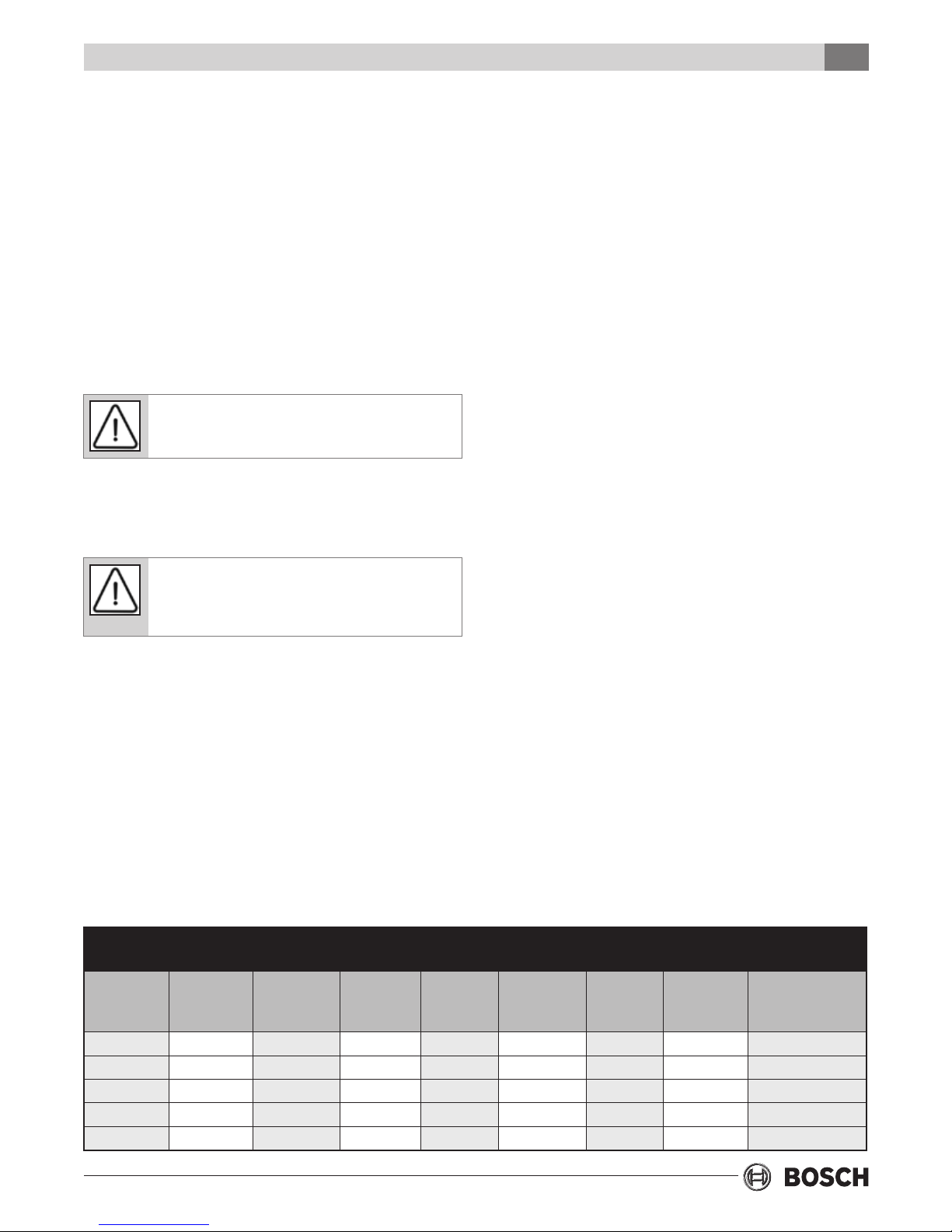
Heater Package Compatibility
Figure 7: Heater Package Compatibility
Model Heater Model KW Heater Amps Circuit MCA Max. Fuse AWG
Min.
208V 240V 208V 240V 208V 240V
CE025 thru 035 HP050-1XS 4.8 17.3 20.0 L1/L2 27.1 30.4 30 30 8
CE049 thru 071 HP050-1XM 4.8 17.3 20.0 L1/L2 27.1 30.4 30 30 8
CE025 thru 035 HP075-1XS 7.2 23.6 30.0 L1/L2 34.9 42.9 40 45 8
CE049 thru 071 HP075-1XM 7.2 23.6 30.0 L1/L2 35.7 43.8 40 45 8
CE025 thru 035 HP100-1XS 9.6 34.7 40.0 L1/L2 48.8 55.4 50 60 6
CE049 thru 071 HP100-1XM 9.6 34.7 40.0 L1/L2 49.5 56.3 50 60 6
CE049 thru 071 HP150-1XM
HP150-1XM
CE049 thru 071 HP200-1XM
HP200-1XM
All heaters rated single phase 60 Hz, and include unit fan load. All fuses type “D” time delay or HACR type breaker or
HRC FORM 1. Wire size based on 60 deg. C copper conductors.
14.4
14.4
19.2
19.2
52.0
34.7
17.3
69.3
34.7
34.7
60.0
40.0
20.0
80.0
40.0
40.0
SINGLE
L1/L2
L3/L4
SINGLE
L1/L2
L3/L4
71.2
49.5
21.7
92.9
49.5
43.4
81.3
56.3
25.0
106.3
56.3
50.0
80
60
25
100
50
45
90
60
25
110
60
50
4
6
10
2
6
6
Units supplied with internal electric heat
require two (2) separate power supplies: one
for the unit compressor and one for the electric
heater elements, blower motor and control
circuit. Refer to Figure #7 for wiring instructions, minimum circuit ampacities and maximum fuse/breaker sizing.
Connection point logic is as follows:
Table 1: Low Voltage Connection Points
Function From
24 HVAC Common C C1 C C
24 VAC Hot R R R R
Fan Operation G G
Reversing Valve (3)
1st Stage
Compressor
Operation
2nd Stage
Compressor
Operation
Condensate
Sensor (1)
Alarm Output
(From UPM) (2)
Auxilliary Electric
Heat (4)
Emergency Heat (4)
Thermostat
O O O O
Y1 Y1 Y1 Y1
Y2 Y2 Y2 Y2
L Splice ALR
W/W1/W2 W1
E EM/W2
To Air
Handler
From Air
Handler
CS CS
Condensing
To
Section
TABLE 1 NOTES
1. For the condensate overow sensor, connect
‘CS’ at the condensing section to ‘CS’ at the
air handler. Be sure to ground power supply.
2. If service LED is utilized connect ‘ALR’
terminal on the UPM board to ‘L’ on the
thermostat sub base. The wiring may be
spliced in the air handling unit. The ‘ALR’
output is hot (R) so check thermostat
instruction manual to ensure compatibility.
3. ‘O’ – reversing valve is energized in the
cooling mode. Fail safe is to heating.
4. Utilized when electric strip heater
package present.
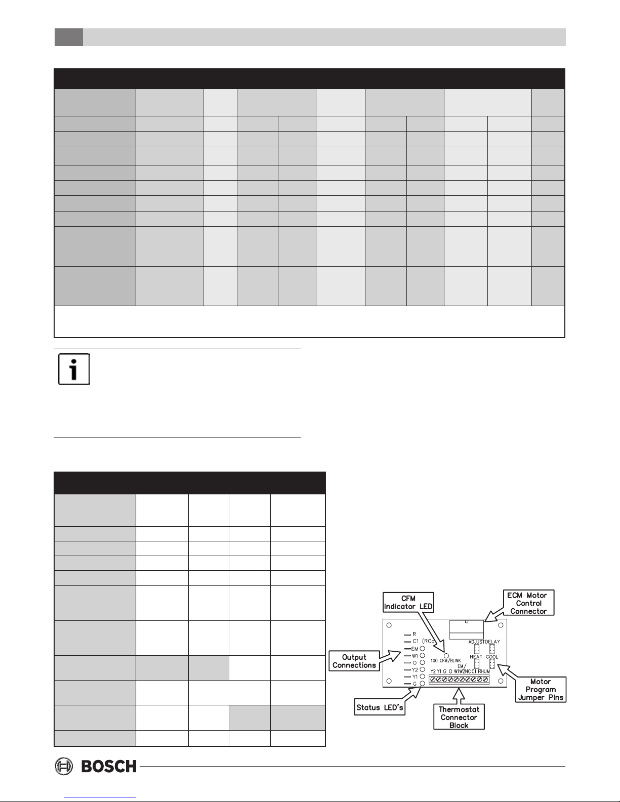
ECM INTERFACE BOARD
Figure #8 - ECM Interface Board
6 720 220 049
Subject to change without prior notice Revised 03-11
Thermostat Connections
CE Split Series
9
THERMOSTAT CONNECTIONS
Thermostat wiring is connected to the 10 pin screw
type terminal block on the lower center portion of
the ECM Interface Board. In addition to providing a
connecting point for thermostat wiring, the interface
board also translates thermostat inputs into control
commands for the variable speed programmable
ECM DC fan motor and displays an LED indication of
operating status. The thermostat connections and
their functions are as follows:
Y2 Second Stage Compressor Operation
Y1 First Stage Compressor Operation
G Fan
O Reversing Valve (energized in cooling)
W1 Auxiliary Electric Heat (runs in
conjunction with compressor)
EM/W2 Emergency Heat (electric heat only)
NC Transformer 24 VAC Common (extra
connection)
C1 Transformer 24 VAC Common (primary
connection)
R Transformer 24 VAC Hot
HUM Dehumidication Mode
If the unit is being connected to a thermostat with a
malfunction light, this connection is made at the unit
malfunction output or relay.
If the thermostat is provided with a malfunction
light powered off of the common (C) side of the
transformer, the unit must be provided with a
malfunction relay (Bosch option # 660-006) to
properly energize the light. The relay coil will
be wired across the (ALR) and (C) contacts on
the unit’s UPM board and the relay’s normally
open contacts across (ALR) and the
malfunction light connection on the
thermostat. If the thermostat is provided with a
malfunction light powered off of the hot (R)
side of the transformer, then the thermostat
malfunction light connection should be
connected directly to the (ALR) contact on the
unit’s UPM board.
To the left of the thermostat connection block are a
row of 2 red and 4 green LED’s. These LED’s indicate
the operating status of the unit. They are labeled as
follows:
EM (red) Emergency Heat On
W1 (red) Auxiliary Heat On
O (green) Reversing Valve Energized, unit is in
cooling mode
Y2 (green) Second Stage Compressor On
Y1 (green) First Stage Compressor On
G (green) Fan On
Just above the connector block is a single red LED
labeled CFM that will blink intermittently when the
unit is running. This LED indicates the air delivery of
the blower at any given time. Each blink of the LED
represent 100 CFM of air delivery so if the LED
blinks 12 times, pauses, blinks 12 times, etc. the
blower is delivering 1200 CFM. Refer to Figure #6 for
factory programmed air delivery settings for the CE
Split Series.
Just above and to the right of the thermostat
connection block are four sets of jumper pins
labeled ADJ, DELAY, HEAT and COOL. The ADJ set of
pins are labeled NORM, (+), (-) and TEST. AP units
will all be set on the NORM position from the factory,
however, airow can be increased (+) or decreased
(-) by 15% from the pre-programmed setting by
relocating the jumper in this section. The TEST
position is used to verify proper motor operation. If a
motor problem is suspected, move the ADJ jumper
to the TEST position and energize G on the
thermostat connection block. If the motor ramps up
to 100% power, then the motor itself is functioning
normally. Always remember to replace the jumper to
NORM, (+) or (-) after testing and reset the unit
thermostat to restore normal operation.
Do not set the ADJ jumper to the (-) setting
when electric heaters are installed. Doing so
may cause the heaters to cycle on their
thermal overload switches, potentially
shortening the life of the switches.
The other three sets of jumper pins are used to
select the proper program in the ECM motor for the
unit. Refer to Figure #7 for the proper jumper
placement.
Always disconnect power before changing
jumper positions on the interface board and
reset the unit afterward.
To the left of the red and green status LED’s is a row
of 1/4” male quick connects. These are used to pass
Revised 03-11 Subject to change without prior notice
6 720 220 049
10
CE Split Series
Safety Devices and the UPM Controller
thermostat inputs on to the rest of the control
circuit. Remember to always turn off unit power at
the circuit breaker before attaching or disconnecting
any wiring from these connections to avoid
accidental short circuits that can damage unit
control components.
SAFETY DEVICES AND THE UPM
CONTROLLER
Each unit is factory provided with a Unit Protection
Module (UPM) that controls the compressor
operation and monitors the safety controls that
protect the unit.
Safety controls include the following:
• High pressure switch located in the refrigerant
discharge line and wired across the HPC terminals
on the UPM
• Low pressure switch located in the unit refrigerant
suction line and wired across terminals LPC1 and
LPC2 on the UPM.
• Optional freeze protection sensor located on the
leaving side of the water coil prevents unit operation
below 35°F or 15°F (depending on dip switch
setting). The freeze dip switch must be set to “ON”.
The factory default for the Freeze setting is in
“ON” position. If the freeze stat option is not
ordered, the switch must be repositioned to the
“OFF” position.
• Condensate overow protection sensor located in
the drain pan of the unit and connected to the
‘COND’ terminal on the UPM board.
The UPM includes the following features:
• ANTI-SHORT CYCLE TIME—5 minute delay on
break timer to prevent compressor short cycling.
• RANDOM START—Each controller has a unique
random start delay ranging from 270 to 300 seconds to
reduce the chances of multiple units simultaneously
starting after initial power up or after a power
interruption, creating a large electrical spike.
• LOW PRESSURE BYPASS TIMER—If the compressor is
running and the low pressure switch opens, then the
control will keep the compressor on for 120 seconds.
After 2 minutes if the low pressure switch remains
open, the control will shut down the compressor and
enter a soft lockout. The compressor will not be
energized until the low pressure switch closes and the
anti-short cycle time delay expires. If the low pressure
switch opens 2–4 times in 1 hour, the unit will enter a
hard lock out and need to be reset.
• BROWNOUT/SURGE/POWER INTERRUPTION
PROTECTION—The brownout protection in the UPM
board will shut down the compressor if the
incoming power falls below 18 VAC. The compressor
will remain off till the voltage goes above 18 VAC and
the anti short cycle timer (300 seconds) times out.
The unit will not go into a hard lockout.
• MALFUNCTION OUTPUT—The controller has a set of
wet contacts for remote fault indication or dry contacts
for communication with a DDC controller or BMS. The
fault output will depend on the dip switch setting for
“ALARM”. If it set to “CONST’, a constant signal will be
produced to indicate a fault has occurred and the unit
requires inspection to determine the type of fault. If it is
set to “PULSE”, a pulse signal is produced and a fault
code is detected by a remote device indicating the fault.
See L.E.D. Fault Indication below for blink code
explanations. The remote device must have a malfunction
detection capability when the UPM board is set to “PULSE”.
• TEST DIP SWITCH—A test dip switch is provided to
reduce all time delay settings to 5 seconds during
troubleshooting or verication of unit operation.
Note that operation of the unit while in test mode
can lead to accelerated wear and premature failure
of the unit. The “TEST” switch must be set back to
“NO” for normal operation.
• FREEZE SENSOR—This is optional and can be set
to ignore or monitor a freeze sensor. There are 2
congurable freeze points, 35°F & 15°F. The unit
will enter a soft lock out until the temperature
climbs above the set point and the anti-short cycle
time delay has expired. The freeze sensor may not
provide protection in the case of loss of ow in the
heating mode. A ow switch or pressure
differential switch is recommended to prevent unit
operation in case of loss of ow.
If unit is employing a fresh water system (no
anti-freeze protection), it is extremely important to
have the “Freeze” switch set to 35°F in order to
shut down the unit at the appropriate leaving
water temperature and protect your heat pump
from freezing if a freeze sensor is included.
6 720 220 049
Subject to change without prior notice Revised 03-11
 Loading...