

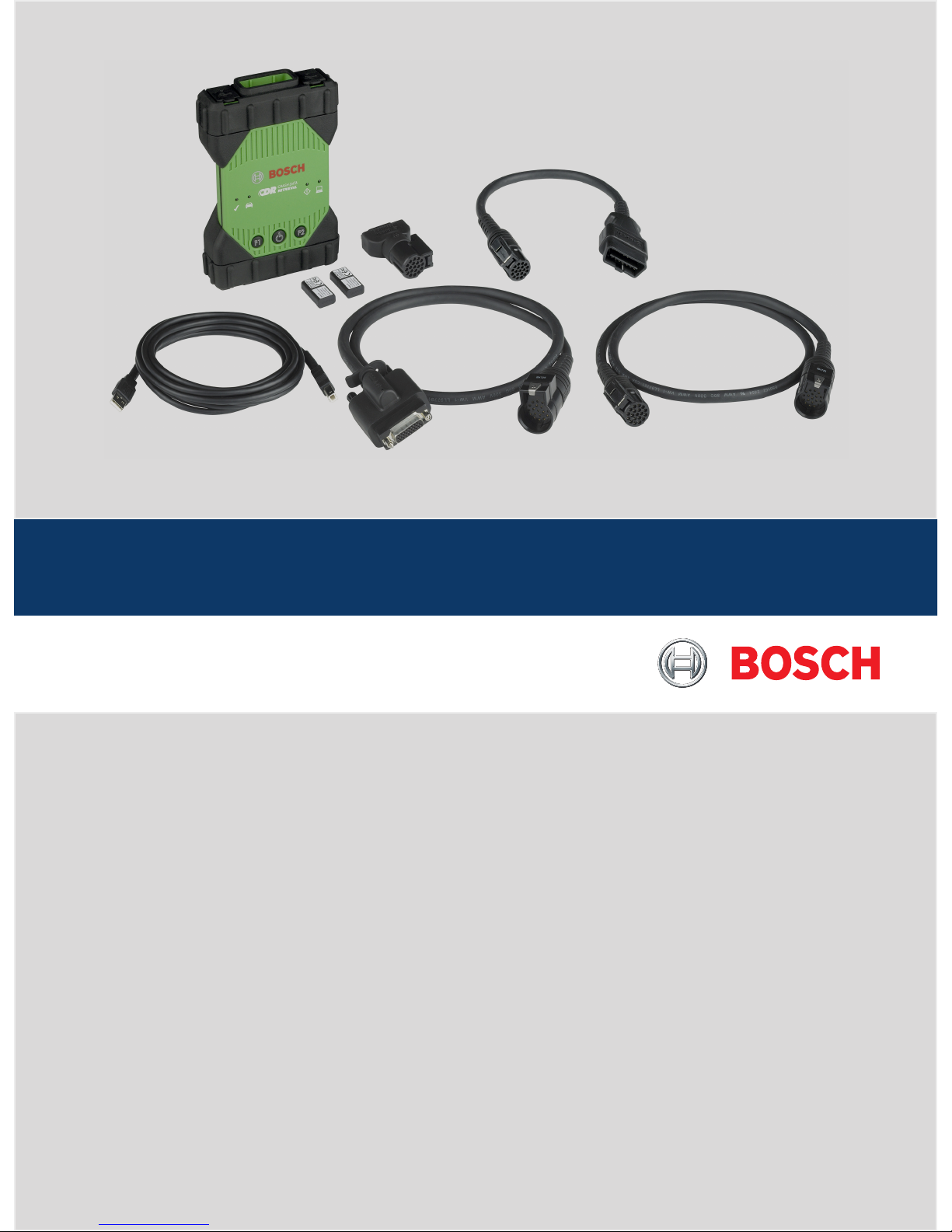
CDR 900
en
User Manual
CDR 900

1699200755 2018-07-01
|
Bosch Automotive Service Solutions Inc.
2 | CDR 900 |
enen
1. Symbols Used 3
1.1 Warning Notices - Structure and Meaning 3
1.2 Symbols in this Document 3
1.3 Symbols on the Product 3
2. User Information 3
3. Safety Instructions 3
3.1 Electromagnetic Compatibility 4
3.2 Electronic Waste Disposal 4
3.3 FCC Compliance 4
4. Product Description 4
4.1 Overview 4
4.2 User group 4
4.3 PC System Requirements 4
4.4 CDR 900 Components 5
4.5 CDR 900 Assembly Connectors, Lights and
Controls 5
4.6 Universal Serial Bus (USB) 6
4.7 Ethernet 6
4.8 Wireless Local Area Network (WLAN) 6
4.9 CDR 900 VCI Manager Software 6
4.10 Additional CDR 900 Features 6
4.11 Supported Interfaces 7
4.12 CDR 900 Component Hardware Descriptions 7
4.13 CDR 900 VCI Manager Software 9
4.14 CDR 900 Software Setup 10
4.15 Setting Up Wireless Communications (software)
11
4.16 Checking CDR 900 Firmware 12
4.17 Power On Self-Test (POST) 12
4.18 Connecting the CDR 900 to a Vehicle 12
4.19 Connecting the CDR 900 to an ECU 13
4.20 Supported Vehicles 13
4.21 Finishing Up 13
5. Troubleshooting 13
5.1 CDR 900 Does Not Pass Power On Self-Test
(POST) 13
5.2 CDR 900 Error LED Lights After Power On 13
5.3 CDR 900 Fails to Power Up 13
5.4 Vehicle LED is Blinking Red 13
5.5 CDR 900 Speaker is Beeping 14
5.6 CDR 900 Turns Off Immediately When
Disconnected from the Vehicle During or After an
EDR Download 14
5.7 CDR 900 Checkmark LED is Blinking 14
5.8 Wireless Communication with Network
Unsuccessful using the Wireless 802.11n Dongle
14
5.9 CDR 900 VCI Manager Displays the Yellow Icon
over the VCI after previous use 14
5.10 PC Application is Unable to Communicate with
the CDR 900 over USB 14
5.11 PC Application is Unable to Communicate with
the CDR 900 over Wireless 15
6. Cleaning and Maintenance 15
6.1 Cleaning and Storing Your CDR 900 15
6.2 Recovering the CDR 900 Software 16
7. Glossary 16
8. Hardware Specifications 17
9. Warranty Information 18
9.1 Limited Warranty 18
9.2 Warranty Exclusions 18
9.3 Warranty Repair Procedure 18
10. Liability, Copyrights and Trademarks 19
10.1 Copyrights 19
10.2 Trademarks 19
1699200755 2018-07-01
|
Bosch Automotive Service Solutions Inc.
Symbols Used | CDR 900 | 3
enen
1. Symbols Used
1.1 Warning Notices Structure and Meaning
Warning notices warn of dangers to the user or people in
the vicinity. Warning notices also indicate the consequences of the hazard as well as preventive action. Warning notices have the following structure:
Warning
symbol
KEY WORD – Nature and source of hazard!
Consequences of hazard in the event of failure to observe action and information given.
! Hazard prevention action and information.
The key word indicates the likelihood of occurrence and
the severity of the hazard in the event of non-observance:
Key word Probability of
occurrence
Severity of danger if instructions not observed
DANGER
Immediate impend-
ing danger
Death or severe injury
WARNING
Possible impending
danger
Death or severe injury
CAUTION
Possible dangerous
situation
Minor injury
1.2 Symbols in this Document
Symbol Designation Explanation
!
Attention Warns about possible property damage.
i
Information Practical hints and other
useful information.
1.3 Symbols on the Product
Observe all warning notices on products and ensure they
remain legible. Important Information
2. User Information
To increase effectiveness with the CDR 900, users
should familiarize themselves with the format and information contained in this guide. Every attempt has been
made to provide complete and accurate technical information based on factory service information available at
the time of publication. However, the right is reserved
to make changes at any time without notice.
Before starting up, connecting and operating Bosch
products it is absolutely essential that the operating instructions/owner’s manual and, in particular, the safety
instructions are studied carefully. By doing so you can
eradicate any uncertainties in handling Bosch products
and thus associated safety risks up front; something
which is in the interests of your own safety and will ultimately help avoid damage to the device. When a Bosch
product is handed over to another person, not only the
operating instructions but also the safety instructions
and information on its designated use must be handed
over to the person.
3. Safety Instructions
Please read and review all instructions, warnings and
information included in this manual prior to start-up,
connection and operation of the CDR 900 Vehicle Communication Interface.
This user manual is written for safe convenient setup
and use of the product. We recommend that you carefully read the manual prior to using the CDR 900 and
software.
DANGER – High Electrical Voltage
Certain risk of personal injury or death
!
Always consult the vehicle's service manual
for safety precautions and procedures when
working with high voltage vehicle systems
and/or passive restraint devices such as
airbags, pretensioners and other deployable
devices.
WARNING – Dangerous Exhaust Gas
Possible risk of personal injury or death
!
When performing any checks with the
engine running in an enclosed space such
as a garage, be sure there is proper ventila
-
tion. Never inhale exhaust gases; they contain
carbon monoxide - a colorless, odorless,
extremely dangerous gas which can cause
unconsciousness or death
WARNING – Parking Brake
Possible risk of personal injury
! To help avoid personal injury, always set the
parking brake securely and block the drive
wheels before performing any checks or re
-
pairs on the vehicle.
CAUTION – Battery Clamps - Polarity
Possible risk of personal injury
!
Do not clasp battery clamps together when
connected simultaneously to the vehicle's 12
volt cigarette lighter or power supply. Reverse
polarity in the vehicle's cigarette lighter may
be present. Damage could occur to the CDR
900 or to the vehicle. Make sure all cables
and adapters are firmly connected before
starting to use the CDR 900. Always read the
instructions completely before attempting a
new procedure.
1699200755 2018-07-01
|
Bosch Automotive Service Solutions Inc.
4 | CDR 900 | Product Description
enen
3.1 Electromagnetic Compatibility
The CDR 900 satisfies the requirements of the EMC
directive 2004/108/EG.
The CDR 900 is a class/category A product as defined
by EN 61 326. The CDR 900 may cause high-frequency
household interference (radio interference) so that
interference suppression may be necessary. In such
cases the user may be required to take the appropriate
action.
3.2 Electronic Waste Disposal
This CDR 900 is subject to European guidelines
2002/96/EG (WEEE). Old electrical and electronic
devices, including cables and accessories or batteries
must be disposed of separately from normal household
waste. Please use the return and collection systems in
place for disposal in your area.
Damage to the environment and hazards to personal
health are prevented by properly disposing of the CDR
900.
3.3 FCC Compliance
This equipment has been tested and found to comply
with the limits for a Class A digital device, pursuant to
Part 15 of the FCC rules. These limits are designed to
provide reasonable protection against harmful interference when the equipment is operated in a commercial
environment.
This equipment generates, uses, and can radiate radio
frequency energy. If not installed and used in accordance with the instruction manual, it may cause harmful interference to radio communications. Operation of
this equipment in a residential area is likely to cause
harmful interference, in which case the user will be required to correct the interference at his or her expense.
All work conducted on electrical devices may be
performed by persons with sufficient knowledge and
experience in the field of electronics.
3.3.1 WiFi Compliance
This equipment complies with the following worldwide
wireless standards.
3.3.2 Safety/Environmental Compliance
This equipment complies with the following worldwide
safety and environmental standards.
4. Product Description
4.1 Overview
The CDR 900 is used by professionals who inspect vehicles involved in accidents, investigate vehicle accidents
or perform vehicle accident reconstructions. It is used
as an aid in accident investigations and vehicle inspections by retrieving stored data from vehicle electronic
systems. The CDR 900 is designed to connect the vehicle to a host PC computer CDR Software application
which then functions though the CDR 900 for retrieval
of certain data such as Event Data Recorder (EDR) data
stored in Electronic Control Units (ECU).
Using the CDR 900 VCI Manager PC application which
is included with CDR Software version 17.8 and later,
you configure the CDR 900 to communicate with a host
computer. The CDR 900 is capable of communicating
over a USB cable or wireless (WLAN).
4.2 User group
The product should be used by skilled and instructed
users only. It is recommended that users be trained, familiarized, instructed or to take part in a general training course before using the CDR 900 to download EDR
data from vehicles or directly from a vehicle's ECU.
4.3 PC System Requirements
The CDR 900 Software runs on a PC/Laptop. The user
interacts with the CDR 900 and CDR Software for device
setup.
The following table lists the minimum PC/laptop requirements for installing and running the CDR 900 and
CDR Software:
Item System requirements
Operating System WIN 7, WIN 8, Or WIN 10 (32 bit
and 64 bit PCs)
Available hard disk space 100 MB or greater
RAM 512 MB or greater
CPU 1 GHZ or higher
Communication Ports 2 USB
Video Resolution 1024 x 768 or higher
1699200755 2018-07-01
|
Bosch Automotive Service Solutions Inc.
Product Description | CDR 900 | 5
enen
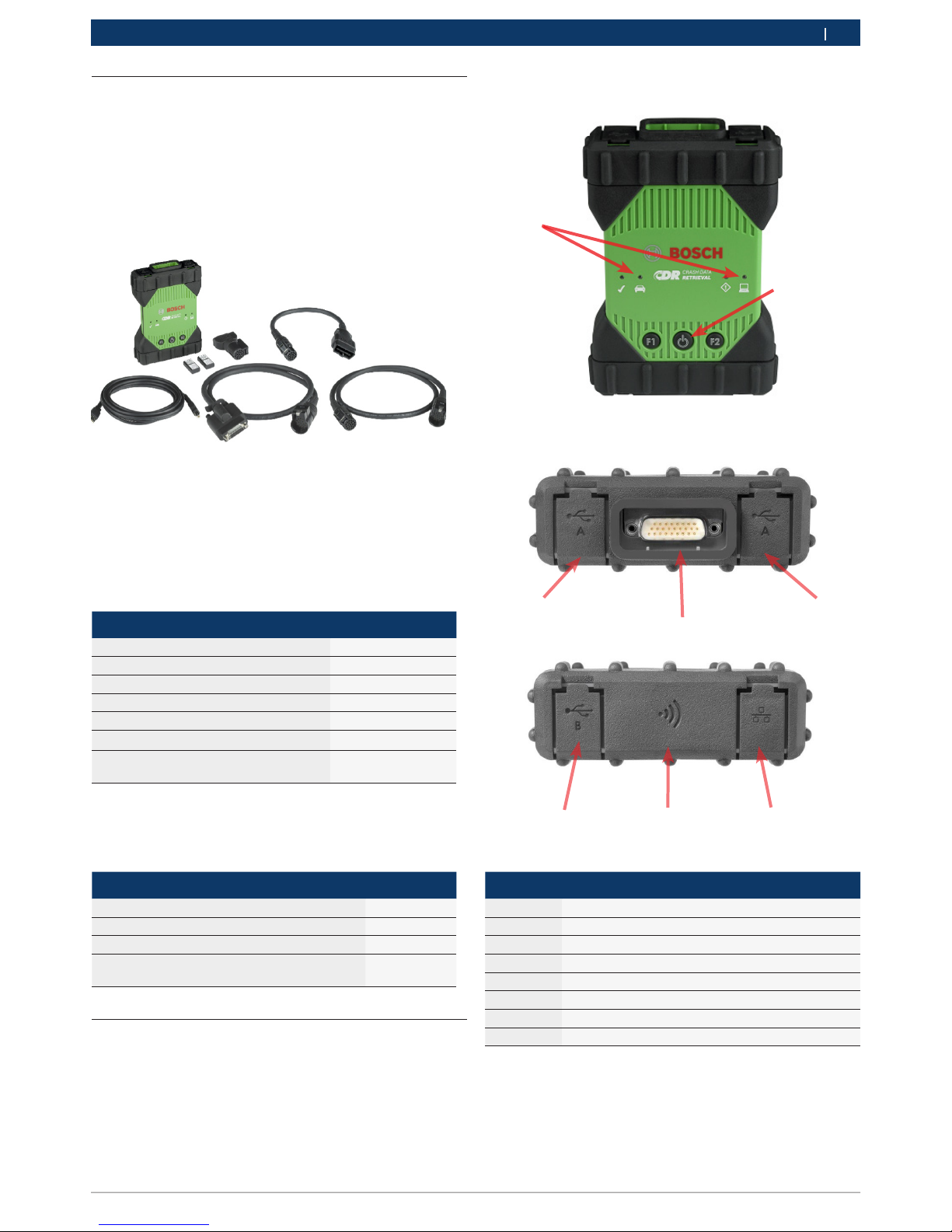
Item Description
1 LED Indicators
2 Power Button with LED indicator
3 USB Port Type A (currently not used for CDR 900)
4 DB26 Connector (CDR Power and Interface cable)
5 USB Port Type A (currently not used for CDR 900)
6 USB Port Type B - PC Connection Port
7 Wireless Adapter
8 Ethernet Port (currently not used for CDR 900)
___
3
4
5
6 7 8
4.4 CDR 900 Components
The CDR 900 components include cables and hardware
needed to connect to and download EDR data from vehicles through the OBD connector or directly from the
vehicle's ECU. Depending on the kit purchased, all of
the cables and components shown below are included
except for the Wireless Dongle. Wireless dongle availability depends upon the country the CDR 900 is sold.
The CDR 900 and its components may be offered in a
few possible kit configurations such as a CDR 900 Upgrade Kit (P/N 1699200630) or kits which may combine
the CDR 900 and the CDR DLC Basic Kit with the older
style CDR vehicle interface (CANplus Module). Regardless of the kit offered, the CDR 900 main components
consist of the following:
CDR 900 Components Part Number Qty
CDR 900 VCI Assembly 1699200598 1
CDR 900 Power and Interface Cable 1699200602 1
CDR 900 DLC/J1962 Cable 1699200615 1
CDR 900 Legacy Cable Adapter (D2ML) 1699200616
CDR 900 1 m Extension Cable 1699200617 1
USB A to B, Heavy Duty 3m Cable 1699200385 1
Wireless 802.11n Dongle (optional depending on where kit is sold)
1699200155 2
Optional accessories for the CDR 900 are listed in the
following table.
Item Part Number
Bosch Storage Case (Nylon Case) F00K108939
CDR 12V Power Supply, with Power Cord F00E900104
CDR 12V Power Supply, without Power Cord 02002435
Wireless 802.11n Dongle (available only in
certain countries)
1699200155
4.5 CDR 900 Assembly Connectors,
Lights and Controls
A number of standard connectors, controls and LEDs
are available on the CDR 900 to facilitate operation and
communication with vehicles, PCs and local area networks. These connectors and controls are shown in the
following illustrations.
1
2

1699200755 2018-07-01
|
Bosch Automotive Service Solutions Inc.
6 | CDR 900 | Product Description
enen
4.6 Universal Serial Bus (USB)
The CDR 900 has a fixed USB configuration which cannot be changed. This ensures that the CDR 900 can
always be connected to a single PC running the CDR
Software version 17.8 or later and the CDR 900 VCI
Manager software so you can configure LAN or WLAN
settings required by your local network. In addition,
it is important to note that a USB connection and 12V
DC power connected through the CDR 900 Power and
Interface cable are required to configure and update
the firmware on the CDR 900. USB connection must be
made directly with the PC port. Do not connect through
a USB hub.
4.7 Ethernet
The Ethernet connection is currently not applicable at
this time for the CDR 900 device.
4.8 Wireless Local Area Network (WLAN)
The 802.11g WLAN connection on the CDR 900 is set
up and configured while the device is connected over
USB to a PC running the CDR 900 VCI Manager software.
4.9 CDR 900 VCI Manager Software
The CDR 900 VCI Manager software is a host computer
application which runs on the Microsoft Windows operating system to configure and update the CDR 900 device such that it can be used to retrieve EDR data from
supported vehicles. The CDR 900 VCI Manager is used
to setup and configure your CDR 900 device so that you
are able to use it with CDR version 17.8 and later CDR
Software. It is also used to update your CDR 900 firmware from time to time.
CDR 900 VCI Manager software comes with CDR version 17.8 and later CDR Software. Access to CDR 900
VCI Manager software is automated through the CDR
Software application.
4.10 Additional CDR 900 Features
4.10.1 CDR 900 Power and Interface Cable
The CDR 900 communicates with vehicles and directly
to Electronic Control Units through the CDR 900 Power
and Interface Cable (P/N: 1699200602). When the Power and Interface is connected to the DLC J1962 Cable
(P/N 1699200615), it provides the link to the vehicle’s
SAE J1962 Data Link Connector (DLC) or OBDII connector. The CDR 900 interface cable can be connected
directly to an ECU using vehicle specific CDR cables for
direct to module downloads. The CDR 900 Interface
cable also switches power to ECUs during retrieval of
EDR data directly from the ECU.
4.10.2 Power Source
The CDR 900 requires 12V DC power for the following
operations:
• CDR 900 Setup & Registration, Reprogramming/
Recovery and Wireless Setup
• Vehicle Communications/EDR retrieval through a
vehicle's J1962 (OBD) connector
• Communications/EDR retrieval while directly connecting to an ECU
4.10.3 Power Source for CDR 900 Setup
When setting up your CDR 900 for the first time, reprogramming, recovering the devices firmware or setting
up wireless communications with your PC, you will
need to connect 12V DC to the CDR 900. To power the
CDR 900 with 12V DC for this purpose, plug in the CDR
900 Power and Interface Cable into the device and then
plug in 12V power connector from the CDR Power Sup-
ply (P/N: F00E900104 or 02002534) into the power jack
on the CDR 900 Power and Interface Cable. Note that
the CDR 900 power supply is the same as the power
supply used with the CANplus CDR interface (P/N:
F00E900104 or 02002534).
4.10.4 Power Source for DLC/OBD Downloads
The CDR 900 can be powered from the vehicle battery
via the DLC Cable when retrieving data through the
vehicle's J1962 (DLC/OBD) connector provided the
vehicle has adequate voltage and the voltage & ground
circuits are not damaged or shorted. If the CDR 900
does not have sufficient power (12V) to connect to the
vehicle's network, the CDR 900 will inform you of insufficient power by blinking the Vehicle LED indicator on
the CDR 900 in the color Red. For example, if there is
no or insufficient 12V power (<~10.5V) to the CDR 900
and it is connected to the USB on your PC, the Vehicle
LED indicator will flash red. If 12V power is lost or not
detected while the CDR 900 is downloading EDR data
from a vehicle, the CDR 900 speaker will also beep to
inform you of the loss of power. Beeping may occur if
the DLC is accidently dislodged as well.
4.10.5 Power Source for Direct to ECU Downloads
The CDR 900 can be used to download EDR data while
directly connecting to an ECU. 12V DC power must be
plugged directly into the CDR 900 Power and Interface
Cable before attempting to download EDR data directly
from and ECU. Also, you must choose the correct CDR

1699200755 2018-07-01
|
Bosch Automotive Service Solutions Inc.
Product Description | CDR 900 | 7
enen
cable for the vehicle data is being retrieved from. Other
external adapters are not required when using the CDR
900. Proper selection and use of the CDR cable and
vehicle application information is provided in the CDR
help file. After connection of 12V DC power, the CDR
Software application will command the CDR 900 Power
and Interface Cable to switch power to the ECU when
needed and then switch it off when data retrieval is
completed.
4.10.6 Use of Older (legacy) CDR Cables
For users who have purchased CDR cables prior to the
release of the CDR 900, they can reuse these cables
with the CDR 900 by using the D2ML Adapter (P/N:
1699200616) to connect a supported ECU to the CDR
900 Power and Interface Cable for retrieving EDR data
from a supported ECU. The legacy CDR cable's 15 pin
connector plugs into one end of the D2ML adapter and
the other end of the adapter plugs directly into the
CDR 900 Power and Interface cable. The CDR Software
works the same as it does with the older CANplus module.
4.10.7 LED Indicators
Seven Light Emitting Diodes (LEDs) are located on the
front of the CDR 900. The LED indicators provide the
following status information.
LED Symbol Function
Vehicle Communication
Error Indicator
PC Host Communication
Power Button
Power On Self-Test
F1 Function 1 (not used)
F2 Function 2 (not used)
4.11 Supported Interfaces
The following sections list the interfaces supported by
the CDR 900. It is not typical that CDR users require
this information but, it is important to note for those
interested the capabilities of the CDR 900.
4.11.1 CDR 900 Physical Layer Interfaces
The following physical network communications are
supported by the CDR 900.
• CAN (3 independent channels)
• Channel 1 at 125/250/500/1000kbps
• Channel 2 at 125/250/500/1000kbps
• Channel 3 at 125/250/500/1000kbps
• Two UART channels (K & L Lines)
• One J1850
• One J1708
4.11.2 Protocol Interfaces
The protocols interfaces supported by the CDR 900 are
as follows. Depending on the vehicle the CDR Tool is
connecting to, the CDR Software automatically chooses
the necessary protocol and physical interface for communication with supported vehicle networks*.
• SAE J1939 (3 independent channels) • SAE J1708/
J1587
• SAE J1850 VPW / PWM
• SAE 2740 (GM UART)
• SAE J2818 – KWP1281
• SAE J2284 at 125/250/500kbps
• SAE J2411 (GM Single Wire CAN) • SAE J2610
• ISO 13400 - DoIP
• ISO 15765
• ISO 14230 – KWP 2K
• ISO 9141-2
• ISO 11898-1 CAN-FD
• ISO 11898-3 (Fault Tolerant CAN) • GMW 3110 (GM
LAN)
*The CDR 900 is capable of supporting the above protocols and physical interfaces; however, this does not
imply the CDR Software actually utilizes all of the listed
protocols and physical interfaces for currently supported vehicles.
4.12 CDR 900 Component Hardware De-
scriptions
4.12.1 CDR 900 Power and Interface Cable (P/N:
1699200602)
This cable is essential for powering the CDR 900 device
during setup, registration, programming and subsequently, connecting to vehicles and ECUs for downloading EDR data. Once connected, you may wish to leave
the CDR Power and Interace Cable connected to your
CDR 900 for continued use thereafter.

1699200755 2018-07-01
|
Bosch Automotive Service Solutions Inc.
8 | CDR 900 | Product Description
enen
Switching 12V Power to ECUs
The CDR Tool is capable of connecting to and retrieving
EDR data directly from ECUs if the vehicle's DLC/OBD
electronics are damaged or not accessible. Connecting
the CDR 900 directly to an ECU to download EDR data
requires a vehicle specific CDR cable and possibly an
adapter such as the CDR 500 FlexRay Adapter. The process also requires providing 12V DC power to the ECU
prior to communicating with it. The CDR 900 supplies
12V DC power to the ECU through the CDR 900 Power
and Interface Cable when a external 12V source such
as the CDR Power Supply (P/N: 02002435) or vehicle
battery is connected to it. At the right time during the
download, the CDR Tool software signals the CDR 900
to switch the 12V DC power through the CDR cable to
the ECU prior to communicating with and downloading EDR data. When completed, the CDR Tool software
switches the ECU power off.
An LED indicator lamp on the CDR 900 power cable
provides status of the power switching to the ECU. The
table below describes the colors of the LED during the
download process.
LED Color Status
Yellow 12V DC power is applied but the power is not
switched to the ECU
Green 12V DC power is switched to the ECU
No Illumina-
tion
12V DC Power is not applied or the cable is
faulty
4.12.2 DLC/OBD J1962 Cable (P/N: 1699200615)
The OBD/DLC J1962 Cable is used when downloading
EDR data when connected to the vehicle's DLC/OBD
connector and the other end plugs into the CDR 900
Power and Interface Cable.
4.12.3 D2ML, CDR Cable Legacy Adapter (P/N:
1699200616)
This is adapter is needed for connecting existing
(legacy) CDR direct-to-module cables to the CDR 900
interface & power cable. Although new CDR 900 direct-
to-module CDR cables will not require this adapter,
many of the existing legacy CDR cables will require this
adapter as older vehicle’s support is migrated to the
new CDR 900 device.
4.12.4 1 m Extension Cable (P/N: 1699200617)
The CDR 900 Extension cable extends the reach of the
CDR 900 during direct-to-module imaging.
4.12.5 USB A to B, Heavy Duty, 3m Cable (P/N:
1699200385)
The USB A to B cable is a heavy duty, 3 meter cable
providing a stable connection between the CDR 900
and PC. Even if wireless is an option, the USB cable is
needed for configuration, reprogramming and registration of the CDR 900.
4.12.6 Wireless 802.11 Dongle (P/N: 1699200155)
Two Wireless 802.11n Dongles provide point-to-point
wireless communications between the CDR 900 and
PC. Depending on the country the CDR 900 is sold,
these dongles may not be provided with the CDR 900.
4.12.7 CDR 12V DC Power Supply (P/N:
F00E900104, kit / 02002435, P/S Only)
The CDR 900 utilizes the current CDR Tool 12V power
supply included in the basic CDR DLC/OBD Kits offered today. Because most users are likely to own one
already, the 12V DC power supply is not included in the
CDR 900 kits.
Getting Started
The following sections provide the information required
to begin using the CDR 900 with CDR Tool Software
version 17.8 and later.
For installation and setup your CDR 900 users will
need a CDR Software subscription to download, install
and activate CDR Tool Software version 17.8 or newer
from the www.boschdiagnostics.com at the following
link: https://www.boschdiagnostics.com/cdr/software-
downloads. CDR Software a subscriptions can be pur-

1699200755 2018-07-01
|
Bosch Automotive Service Solutions Inc.
Product Description | CDR 900 | 9
enen
chased from an authorized CDR Tool distributor in the
customer's region or country. Click on the following link
or visit the URL listed for further instructions on installing the latest CDR Tool software: https://www.boschdi-
agnostics.com/cdr/sites/cdr/files/CDR_software_Installation_Manual_31_0_0_0_2.pdf
4.13 CDR 900 VCI Manager Software
Through out this manual, you will see references to the
CDR 900 VCI Manager Software (VCI Manager (CDR)).
This software comes as part of the CDR Tool Software
version 17.8 and later and gets installed automatically
during its installation. CDR 900 VCI Manager software
enables the connection of the CDR 900 to a PC, reprogramming the device with updates as needed, recovering it in case of rare error conditions and recovering the
device for first time use. The CDR Tool Software will
interact with the CDR Manager software when needed
but users can also launch the Manager software from
the program file start menu under the BOSCH menu as
well.
To get started, users must Setup and Register the CDR
900 through the CDR Software application by opening
CDR Tool Software version 17.8 or newer and follow the
instructions provided when clicking on How to Setup
and Register CDR 900 from the Register CDR 900 Device
selection under the Setup menu in the CDR Tool Software.
The instructions will guide users through the process
of setting up and registering their CDR 900. Below is
a summary of the steps required before using the CDR
900:
1. Program (recover) the CDR 900 for the first time
2. Configure the CDR 900 for Wireless operation (opti-
onal)
3. Register the CDR 900 with the CDR Tool software
Setup and Registration is also covered in this user
document. It is recommended however, that users refer
to the CDR Tool Software for the latest instructions on
getting the CDR 900 setup and registered for use.
4.13.1 CDR 900 Wireless Setup (Hardware)
The CDR 900 can be configured to communicate with
the PC wirelessly using the two Wireless Dongles (P/N:
1699200155). Using the Wireless Dongles allows the
PC to connect to the CDR 900 through a simple pointto-point wireless connection. This is the preferred
method for connecting the CDR 900 to a PC wirelessly.
First, the a wireless dongle must be installed into the
CDR 900. Use the following procedure to install the
wireless adapter into your CDR 900.
1. Ensure power is removed from CDR 900.
2. Remove the lower boot from the CDR 900.
3. Install the wireless adapter into the USB port.
4. Replace the lower boot on the CDR 900.
Next, install the second wireless dongle from your kit
into the PC. Use the following procedure to install your
wireless dongle into your PC.
1. Identify a USB 2.0 compatible port on your PC that
is accessible. Do not plug wireless adapter into a
USB hub.
2. Install the wireless adapter into the PC USB port.
You may have to wait for your PC to install and configure the wireless adapter driver onto your PC.
Your PC and CDR 900 hardware is now ready for a wireless connection.
Reminder: You should always use Windows to Safely
Eject the wireless adapter before physically removing it
from your PC.
4.13.2 Identifying Your CDR 900 by Serial Number
The best way to keep track of your CDR 900 is by referring to the Serial Number on the back label of the CDR
900. It is the last 8 characters of the product identifica-
tion code located directly below the bar code on the
label. The CDR 900 can be also identified electrically
using the same serial number as imprinted on the label.
You may need to refer to this serial number when you

1699200755 2018-07-01
|
Bosch Automotive Service Solutions Inc.
10 | CDR 900 | Product Description
enen
are using or registering your CDR 900 with your CDR
Tool Software.
4.14 CDR 900 Software Setup
This section outlines the setup of your CDR 900 software.
4.14.1 CDR 900 and its First Time Use
The CDR 900 is shipped from the factory without
firmware on the device. Your first connection to a PC
involves programming the CDR 900 which consists of
"recovering" the device with the new firmware. Before
doing so, you will need to power up the CDR 900 and
connect to the USB cable to configure your CDR 900.
Follow the steps below to install CDR 900 firmware for
the first time.
1. Launch CDR Tool Software and select Program CDR
900 from Program CDR Devices under the Setup
menu. The CDR 900 VCI Manager will be displayed
and ready to connect to the device. Before proceeding to the next step, make sure 12V DC power from
your CDR Power Supply (P/N: 02002435) is plugged
into the CDR 900 Power and Interface Cable and
the CDR 900 is connected to the PC using the USB
cable. The CDR 900 will boot in Recovery Mode
(only in factory setup the first time use)
2. When you click on the new CDR 900 icon in the CDR
900 VCI Manager screen, the Connect button will
change to the Recover button. Your CDR 900 will be
displayed without the serial number when initially
connected to CDR 900 VCI Manager.
3. Select the Recover button to start the update process.
4. Select the Start Update button to install firmware on
the CDR 900.
5. Do not unplug the CDR 900 from the PC or remove
power from the CDR 900 during the update process.
Select OK to continue.
6. The update process will take about 5 minutes to
complete. Once the update process is complete the
CDR 900 will automatically reboot. Wait until you
hear the beep from the CDR 900 before proceeding
to use your CDR 900. Proceed only after you hear
the beep.
7. The CDR 900 icon in the CDR 900 VCI Manager will
indicate it is ready to connect to the PC. Click on the
CDR 900 icon in the manager window and then click
the Connect button on the screen. A green check
mark will be displayed when you are successfully
connected. Below are the possible connection icon
statuses that may be displayed in the CDR 900 VCI
Manager window depending on how the CDR 900 is
connected to the PC.
Icon Description
CDR 900 VCI Manager will connect to CDR 900
via USB
CDR 900 VCI Manager is connected to the CDR
900
CDR 900 VCI Manager will connect to CDR 900
via Wireless

1699200755 2018-07-01
|
Bosch Automotive Service Solutions Inc.
Product Description | CDR 900 | 11
enen
Icon Description
Wireless Point-to-Point is not set up. Connect
CDR 900 to the PC using USB cable to complete
setup.
Wireless adapters in the PC and in the Tester
are incompatible with each other.
Once the CDR 900 is able to communicate with your PC
the CDR application all you need to do is register the
device with the CDR Tool Software and then it is ready
to use.
4.14.2 Registering the CDR 900
The CDR Tool Software requires a CDR 900 device to
be registered before downloading EDR data from supported vehicles. Follow the steps below to register you
CDR 900 with the CDR Software. If you wish to use
another CDR 900 device after one is already registered
then you will need to un-register it and register the new
device in its place. Registration can only be completed
when the CDR 900 is connected to the PC with the USB
cable and 12V power is supplied to it. Registration cannot be performed over wireless connection.
1. Launch CDR Tool Software version 17.8 or newer.
2. Connect the CDR 900 to your PC using the USB
cable. Make sure you also provide 12V power to the
device.
3. Select Register a Device from the Register CDR 900
Device selection from the CDR Tool Software Setup
menu
4. Your device will be registered and is evident when
viewing the dropdown menu under Register CDR
Devices (see below)
To un-register a device, simply select Un-Register Your
Device from the same menu selection and your CDR 900
information will be removed.
4.15 Setting Up Wireless Communications
(software)
The CDR 900 is capable of communicating with a PC
over a Point-to-Point wireless connection. This connection requires the use of the two Wireless 802.11 Dongles (P/N: 1699200155) which may have been included
in your CDR kit or can be purchase separately. Refer
to section 5.2.2 CDR 900 Wireless Setup (Hardware) for
setting up your CDR 900 and PC hardware to communi-
cate wirelessly. This section describes how to get your
CDR 900 software to communicate wirelessly over a
Point-to-Point network and assumes the wireless dongles are already installed.
The following illustration shows a CDR 900 connected
to a laptop PC using Point-to-Point Wireless communication.
Note that the steps presented below assume you are
running Windows 7 operating system on your PC. The
steps for other versions of the Windows operating system may be slightly different.
1. Connect the CDR 900 to your PC using the USB
cable. Do not plug the CDR 900 USB cable into a
USB hub.
2. Apply 12V power to CDR 900 Power and Interface
Cable then allow the CDR 900 to boot completely
(listen for the beep).
3. Launch the CDR Tool Software and select Program
CDR 900 from the Setup menu. This step launches
the CDR 900 VCI Manager Software.
4. Click the CDR 900 Icon in the view and click Connect.
5. Remove the USB cable from the PC and CDR 900
and you should be connected wirelessly. You will
see the following icon in the CDR 900 VCI Manager
screen confirming a wireless connection.
6. The next time you apply 12V power to the CDR 900
either through a DLC/OBD connection to a vehicle or
when 12V power is supplied to the CDR 900 directly
to the CDR 900 cable, the wireless connection is
automatically configured. As long as your CDR 900 is
registered prior to setting up the wireless, the CDR
Tool application is ready to connect to the device
when applicable.
! IMPORTANT: Wireless connections between the CDR
900 and PC may not be supported on all PC and network configurations including PCs running a Virtual
Private Network (VPN). This is not due to limitations
of the CDR 900 hardware and software but may be
due to the user's PC, corporate network and security requirements and settings. Operation limita-

1699200755 2018-07-01
|
Bosch Automotive Service Solutions Inc.
12 | CDR 900 | Product Description
enen
tions presented by the above may not be resolved
by Bosch and subsequent operation of the wireless
features may not be possible.
i The range of the CDR 900 wireless may reach up
to 100 meters with no obstructions between the
CDR 900 and PC; however, this range cannot be
guaranteed as it can vary based on background RF
(radio frequency) noise in the environment it is used.
Also, keep in mind that the number, thickness and
location of walls, ceilings, or other objects that the
wireless signals must pass through may limit the
range and data communication rates significantly. To
ensure proper operation with the CDR Software, it is
recommended not to exceed 10 meters between the
CDR 900 and PC.
4.15.1 Changing the Wireless Point-to-Point PassPhrase
A default wireless pass-phrase is provided through the
CDR 900 VCI Manager software and does not need to
be entered during Point-to-Point wireless setup. If you
have the need to reset your pass-phrase, you can use
the following steps. The following steps assume you are
running the Windows 7 operating system on your PC.
1. On the right-hand side of the Windows Task Bar,
click the View Wireless Networks button. A list of the
available wireless networks in range of your PC is
displayed.
2. Select Open Network and Sharing Center.
3. Select Manage Wireless Networks from the left
column.
4. Select Change adapter menu and choose CDR 900
from the list.
5. Remove your stored Point-to-Point network. The
name will contain CDR 900 and the last 8 digits of
the CDR 900 serial number, (CDR 900 xxxxxxx).
6. When you reconnect the CDR 900 to the PC using
the USB cable, a new pass-phrase will be established.
4.16 Checking CDR 900 Firmware
The CDR Tool software has a Test CDR 900 option
which connects to the application to the registered
CDR 900 and verifies the device can be communicated
with and that is has the latest software. Users must ensure that the CDR 900 is connected via the USB cable
and 12V power is applied to the CDR 900 before testing
the device.
If the CDR 900 firmware needs to be updated, the user
will be notified via a popup screen and asked if they
wish to reprogram the device. The user may choose to
update at that time or reprogram the CDR 900 at a later
time using the Program CDR 900 from the Setup menu.
CDR 900 Software can only be updated when connected to the PC with the USB cable and not through a
wireless connection.
4.16.1 Set Factory Default for Wireless
Selecting the Set Factory Default button on the Network Setup tab of the CDR 900 VCI Manager reconfigures your CDR 900 to the Point-to-Point communications settings it had when it left the factory. Any software upgrades that have been installed to the CDR 900
are still installed. When the CDR 900 reset is finished,
the CDR 900 VCI Manager software displays the VCI
Explorer tab. All wireless AP configurations will be lost.
4.17 Power On Self-Test (POST)
When you first apply power to a CDR 900 with firmware, the Power On Self-Test (POST) runs. You should
observe a sequence of lights and hear the “BEEP’ indicating that the CDR 900 is working properly.
If a failure occurs, one long audible beep will be heard
and a Test Failure light sequence displays which includes the red Error LED.
4.18 Connecting the CDR 900 to a Vehicle
The CDR 900 kit includes an interface cable (CDR 900
Power and Interface Cable) and a DLC/OBD J1962 Cable. These cables are used to connect the CDR 900 to
the vehicle’s SAE J1962 Data Link Connector (DLC).
Refer to the electrical wiring diagram for the vehicle
you are testing to determine the location of the DLC on
the vehicle.
1. Connect the 26-pin end of the CDR 900 Power and In-
terface cable to the top of the CDR 900, then tighten
the screws.
2. Connect the DLC/OBD J1962 to the CDR 900 Power
and Interface cable
3. Connect the 16-pin end of the J1962 cable to the
vehicle DLC connector.
4.18.1 Powering the CDR 900

1699200755 2018-07-01
|
Bosch Automotive Service Solutions Inc.
Troubleshooting | CDR 900 | 13
enen
The CDR 900 will be powered by the vehicle’s 12-volt
battery. If power is not available through the vehicle's
DLC/OBD connector, the user can use the CDR Tool
cigarette lighter adapter connected to the CDR 900
Power and Interface cable to power up the CDR 900.
4.19 Connecting the CDR 900 to an ECU
The CDR 900 kit includes an interface cable (CDR 900
Power and Interface Cable) which connects directly to
vehicle specific CDR cables for downloading data while
directly connecting to an ECU. An adapter is also provided which allows the CDR 900 to connect with older
CDR cables which were released prior to the CDR 900.
Refer to the CDR Tool Software help file for determing
which CDR cable to use for supported vehicles.
4.19.1 Powering the CDR 900 for Direct ECU connections
The CDR 900 is powered using the CDR power supply
connected directly to the CDR 900 Power and Interface
Cable. Also, the CDR Tool cigarette lighter adapter can
also be used to power the CDR 900 utilizng a 12V power source from the vehicle.
4.20 Supported Vehicles
The CDR Tool Software (version 17.8 and later) help file
contains a Vehicle and Cable Lookup section which lists
all of the supported vehicles by the CDR Tool and the
CDR 900. Always refer Vehicle and Cable Lookup section
for vehicles which are supported by the CDR 900.
4.21 Finishing Up
After using the CDR 900, a few simple steps help you
leave the vehicle electronic system(s) in the proper
state and ensure that you get the most use out of your
diagnostic tools:
1. Before turning the CDR 900 off, exit any running PC
computer applications.
2. Turn the CDR 900 off by removing power. The Power
LED turns off.
3. Disconnect the CDR 900's DLC cable from the ve-
hicle.
4. Disconnect the USB cable from the PC and the CDR
900.
5. Store the CDR 900, cables, and other parts in a
secure, dry location.
5. Troubleshooting
This section is intended to help you get back on track
if the CDR 900 appears to be operating abnormally. In
addition, the most likely cause for the condition is given
as well as other possible causes and recommendations
on how to isolate or eliminate the problem.
5.1 CDR 900 Does Not Pass Power On
Self-Test (POST)
Most Likely Cause:
• Internal problem in the CDR 900.
Recommendations:
• Connect the CDR 900 to a PC using USB and per-
form the recovery procedure.
5.2 CDR 900 Error LED Lights After
Power On
Most Likely Cause:
• A problem has been detected during power on.
Recommendations:
• Power down the VCI and verify that it has the same
problem when you power up again.
• Connect the VCI to a PC using USB and perform
the recovery procedure.
5.3 CDR 900 Fails to Power Up
The CDR 900 should power up as soon as external
power is applied through the CDR Power and Interface
Cable. If the CDR 900 does not turn on, first check the
cable connections. Try supplying power to the device
from two different power sources— the vehicle DLC connector and the USB connector.
Recommendations:
• Check that the cables are securely attached to the
VCI and the connector pins are clean.
• If connecting to the vehicle DLC connector, try
powering from the USB connector.
• If powering from USB, try powering from the ve-
hicle DLC connector.
5.4 Vehicle LED is Blinking Red
If the CDR 900 does not detect 12V on Pin 16 of the
DLC cable or that power is appled to CDR 900 Power
and Interface Cable, the CDR 900 will inform the user by
automatically turning on and blinking the Vehicle LED

1699200755 2018-07-01
|
Bosch Automotive Service Solutions Inc.
14 | CDR 900 | Troubleshooting
enen
icon red. This condition might be seen if the CDR 900
is only powered by a 5V USB connection from your PC
or if the OBD Cable has accidently been disconnected
from the vehicle Data Link Connector (DLC/OBD) and
is powered from the backup capacitor inside the device
When the CDR 900 detects 12V on Pin 16 or when powered though the cable, the Vehicle LED will stop blinking red.
Recommendations:
• Ensure 12V is applied to the CDR 900 Power and
Interface Cable or Pin 16 of the DLC/OBD cable
5.5 CDR 900 Speaker is Beeping
If the CDR 900 is performing diagnostic services for the
PC and does not detect 12V on Pin 16 of the DLC cable,
the CDR 900 will inform the user of the loss of power
by beeping the speaker. The CDR 900 will continue to
beep until the backup capacitor is drained. When the
CDR 900 detects 12V on Pin 16, the speaker will stop
beeping.
Recommendations:
• Ensure 12V is applied to Pin 16 of the DLC cable
during a download or that 12V power is supplued
to the CDR 900 through the CDR 900 Power and
Interface Cable.
5.6 CDR 900 Turns Off Immediately
When Disconnected from the Vehicle
During or After an EDR Download
If the CDR 900 does not remain on during a DLC disconnection, there may be a problem charging the internal capacitor.
The CDR 900 should remain powered up if power is
lost during engine cranking or after it is disconnected
from power (vehicle DLC) during a diagnostic session.
The CDR 900 speaker will beep to notify the user that
power has been lost unexpectedly during the diagnostic
session.
Recommendations:
• Check for 12V power supply at the vehicle DLC connector
• Ensure that the CDR 900 has been connected to
the vehicle DLC for at least 90 seconds to charge
the internal capacitor.
5.7 CDR 900 Checkmark LED is Blinking
If the internal temperature of the CDR 900 has exceeded the maximum limit, the CDR 900 will automatically
turn off the wireless adapter. This will be visible to the
user by the Checkmark LED blinking. When the internal
temperature of the CDR 900 lowers to an acceptable
value, the wireless adapter will be re-enabled for wireless communication.
Recommendations:
• Move the CDR 900 to a cooler location near the
vehicle
5.8 Wireless Communication with Net-
work Unsuccessful using the Wireless 802.11n Dongle
The wireless dongle communication to a network. The
wireless dongle is only intended to be used with the
CDR 900 for Point-to-Point communication or Infrastructure wireless communication.
Recommendations:
• Make sure you do not have two D-Link wireless
dongles connected to the PC.
• Make sure you are not trying to connect the PC
to your dealership network using the DWA131 E1
dongle.
5.9 CDR 900 VCI Manager Displays the
Yellow Icon over the VCI after previous use
There may be instances when Windows does not recognize the installation of the wireless dongle. In these
cases, Windows may create a new wireless profile instead of using the existing one already stored on the
PC. The yellow icon displayed over your CDR 900 instructs you to plug in the USB cable between the CDR
900 and the PC.
Recommendations:
• Always use Windows to safely Eject the wireless
adapter before physically removing it from your PC.
• Unplug and then re-install your wireless adapter.
Windows will attempt to recognize the wireless
adapter. If successful, the yellow icon will disappear and the CDR 900 will be ready for wireless
Point-to-Point communication.
5.10 PC Application is Unable to Commu-
nicate with the CDR 900 over USB
CDR 900 VCI Manager Software must be installed on
the PC, and the CDR 900 must be powered up before
it will communicate. The CDR 900 must be configured
through USB before it will communicate using any other
connection types.
Recommendations:
If other applications including the CDR 900 VCI Manager are able to connect to the CDR 900 then:

1699200755 2018-07-01
|
Bosch Automotive Service Solutions Inc.
Cleaning and Maintenance | CDR 900 | 15
enen
• Check the Windows Firewall settings to see if the
application is being blocked.
If all installed applications are unable to communicate
with the CDR 900 then:
• Connect the CDR 900 to the PC using USB but
do not connect it to the vehicle, Do not connect
through a USB Hub or a repeater cable.
• Verify that the USB cables are securely attached
and the CDR 900 has completed its power up sequence
• Launch the CDR 900 VCI Manager Application by
selecting Program CDR 900 from the CDR Tool software
• Does CDR 900 VCI Manager detect the device?
If NO, then:
• Try a different USB Cable / Port on the PC
• Check the Windows Firewall to see if the CDR
900 VCI Manager is Blocked. Check that the
CDR 900 USB connection is detected by Windows:
• From the Windows Control Panel, open the
Network and Dial-up Connections window.
• Check for device name "Bosch VCI". If not running, then the USB driver has not been loaded
on the PC. Perform the following troubleshooting steps.
1. Unplug the USB cable from the PC and
plug it back in to the same USB port on the
PC. Continue if not resolved.
2. Unplug the USB cable from the PC and
plug it back in to a different USB port on
the PC. Continue if not resolved.
3. With the CDR 900 plugged into the PC with
a USB cable, open the device manager
from the Windows control panel. In device
manager search for an unknown or improperly configured device. The CDR 900 will
likely be detected as one of the following:
• Other device – RNDIS/Ethernet
Gadget with a yellow exclamation
icon
• Universal serial bus controllers – Unknown USB Device
• Right click on the device name in device manager > Update Driver > Browse
my computer for driver software >
Browse > C:\Program Files (x86)\Bosch
Software\USBDriver
4. Plug a different CDR 900 device (VCI #2)
into the PC (PC #1). Continue if not resolved.
5. Plug the original CDR 900 device (VCI #1)
into a different PC (PC #2) with CDR 900
VCI Manager software installed on it.
6. Contact Technical Support.
If YES, then:
• Test if connection lost when the CDR 900 is
connected to the Vehicle, then...
• Check for Ground faults - (Battery Chargers, Hoists…) This issue may be resolved
by correcting the ground fault or configuring the CDR 900 to connect wireless or
Ethernet.
• Check for an improperly wired DLC connector
• If the CDR 900 VCI Manager is still not able to communicate with the CDR 900, perform the Recovery
Procedure on the CDR 900.
5.11 PC Application is Unable to Commu-
nicate with the CDR 900 over Wireless
Check that the wireless card is properly seated in the
CDR 900.
• Confirm the CDR 900 can connect over USB
Confirm the PC has a single dongle connected:
• Connect the CDR 900 to the PC using USB
• Confirm the communication is enabled and the IP
configuration is properly set using the CDR 900 VCI
Manager software
6. Cleaning and Maintenance
6.1 Cleaning and Storing Your CDR 900
The housing of the
CDR 900
module may only be
cleaned using a soft cloth and a neutral cleaning agent.
Do not use any abrasive cleaning agent or rough cleaning
cloths.
There are no user serviceable components inside the
CDR 900 Vehicle Communication Interface. Do not
open the device. Opening the device will void the warranty.
• If the VCI, connectors, or cables become dirty, they
may be cleaned by wiping them with a rag lightly
coated with a mild detergent or non-abrasive hand
soap.
• Do not immerse the VCI or any of its parts or acces-
sories in water.

1699200755 2018-07-01
|
Bosch Automotive Service Solutions Inc.
16 | CDR 900 | Glossary
enen
• Although the VCI and accessories are water resistant, they are not waterproof; thoroughly dry them
prior to storage.
• Avoid using harsh solvents such as petroleum
based cleaning agents, Acetone, Benzene, Trichloroethylene, etc.
6.2 Recovering the CDR 900 Software
As a result of a power failure or a communications error
during a software update, the CDR 900 software may
become corrupted. You may see several symptoms such
as error messages directing you to go to RECOVERY
mode or an inability to connect to a detected CDR 900.
The following two error messages generally occur during CDR 900 Tester Software download. If you see
either of these messages, perform the Recovery Procedure.
• "Error reprogramming the VCI. Go to Recovery
Mode."
• "There was a problem reprogramming the VCI"
6.2.1 Recovery Procedure
Use the following procedure to recovery the software
on the CDR 900.
1. Press and hold the Power button of the CDR 900
down. Release the button when the red Error LED
is illuminated. After Error LED is illuminated, the
CDR 900 is ready for recovery and the Error LED
will remain on.
2. Start the CDR 900 VCI Manager software by clicking the CDR 900 VCI Manager icon on your desktop.
Your CDR 900 must be connected via USB or it will
not be recognized.
3. When the CDR 900 is detected by the CDR 900 VCI
Manager software, the icon will be labeled with
"Recover".
4. Select the CDR 900 without the serial number and
click the Recover button. The CDR 900 VCI Manager
software switches automatically to the CDR 900
Update tab.
• The Recovery Procedure removes any embedded application software loaded on the CDR
900. Your network settings will be retained.
5. Select the latest version of the CDR 900 Recovery
Image and click Start Update. Do not unplug the
CDR 900 from the PC or remove power from the
CDR 900 during the recovery process.
6. When you see the message indicating that the CDR
900 will automatically restart, click OK. The CDR
900 VCI Manager software switches automatically
to the VCI Explorer tab, and your CDR 900 appears
when it has finished the restart and Power On Self
Test (POST).
7. Glossary
Here is a glossary of terms commonly used in the Automotive Diagnostics industry. For CDR Tool terms, refer
to the CDR Tool Software Help File.
TERM DESCRIPTION
TERM DESCRIPTION
AC ALTERNATING CURRENT
BAUD RATE THE SPEED AT WHICH DATA IS TRANS-
FERRED OVER A SERIAL DATA LINK
BPS BITS PER SECOND
CDR CRASH DATA RETRIEVAL
CURSER HIGHLIGHTED TEXT OR DATA ON A DIS-
PLAY SCREEN
DC DIRECT CURRENT
DCE DATA COMMUNICATION EQUIPMENT
DLC DATA LINK CONNECTOR
DTE DATA TERMINAL EQUIPMENT. A TERM
USED TO DESCRIBE A DEVICE CON-
NECTED TO AN RS232 LINK.
ECM ENGINE CONTROL MODULE
ECU ENGINE CONTROL UNIT
EEPROM ELECTRONICALLY ERASABLE PROM
ETHERNET STANDARDIZED IEEE 802.3 TWISTED-
PAIR WIRE FOR CONNECTING SYSTEMS
TO A NETWORK.
HZ HERTZ - A UNIT OF MEASURE FOR FRE-
QUENCY
I/F INTERFACE
I/O INPUT/OUTPUT
I/P INSTRUMENTATION PORT
LAN LOCAL AREA NETWORK
LED LIGHT-EMITTING DIODE
OBD ON BOARD DIAGNOSTICS
OEM ORIGINAL EQUIPMENT MANUFACTURER
PC PERSONAL COMPUTER
RCV RECEIVE
RS232 SAME AS RS232C
RS232C THE MOST STANDARD SERIAL COM-
MUNICATION INTERFACE USED IN THE
COMPUTER INDUSTRY
SCI SERIAL COMMUNICATION INTERFACE
USB UNIVERSAL SERIAL BUS - A COMMON
STANDARD FOR INTERFACING WITH A
PC
VCI VEHICLE COMMUNICATION INTERFACE
CDR 900 VCI MAN-
AGER
PC SOFTWARE THAT CONFIGURES,
TESTS, AND UPDATES THE CDR 900
VDC VOLTS DC
WLAN WIRELESS LOCAL AREA NETWORK

1699200755 2018-07-01
|
Bosch Automotive Service Solutions Inc.
Hardware Specifications | CDR 900 | 17
enen
8. Hardware Specifications
The following table lists the various hardware characteristics of the CDR 900.
CDR 900 HARDWRE SPECIFICATIONS
HOST INTERFACE
Wired USB High Speed Client Port
(480 Mbps)
Ethernet 10/100 Mbps
Wireless 802.11b/g/n on USB Dongle
Bluetooth Version 2.0 EDR on
USB Dongle
PROCESSOR SYSTEM
Microprocessor Type I.MX6 Solor Processor
Clock Speed 800 MHz
RAM SDRAM : 512 Mbytes DDR3:
64M X 32
ROM NAND Flash: 256 Mbytes
Mass Storage Micro SD Card Slot – No
card installed (Optional from
4Gbyte to 128Gbyte)
USER INTERFACE
LED 4 LED’s - two LED’s are du-
al color
Audio Beeper (software frequency
controlled)
Keypad 3 momentary switches plus 3
back-lighting LED’s
Switch Recovery switch (for restora-
tion of fail-safe software)
POWER
Vehicle (12V) From vehicle battery via DLC
External (12V) - From CDR Power Supply
(P/N: 02002435)
- From vehicle battery via bat-
tery clips
- From 12V jump box
External USB power
Backup 15 seconds typical (5F Ultra-
Cap)
MECHANICAL CHARACTERISTICS
Size 1635mm x 115mm x 40mm
Weight 240 grams
Input Voltage 6VDC to 16VDC
Power Sources • 9 - 16 Volt vehicle power
• USB power
Operating temperature -20ºC to 70ºC using intelligent
staged temperature management and shutdown

1699200755 2018-07-01
|
Bosch Automotive Service Solutions Inc.
18 | CDR 900 | Warranty Information
enen
9. Warranty Information
9.1 Limited Warranty
Bosch Automotive Service Solutions Inc. warrants the
CDR 900 and related cables and adapters (Bosch CDR
Products) it distributes through distributors authorized
to sell Bosch products to be free from defects in material and workmanship, in accordance with the following:
For 24 months after delivery to you of the Bosch CDR
900 Product, the original end user, we will repair or at
our option replace at no charge to you any such Bosch
CDR Product which, under normal conditions of use
and service, proves to be defective in materials or workmanship (excluding batteries). The warranty period for
cables, adapters and accessories is 12 months. The
warranty on replaced parts is 90 days.
This warranty does not cover expenses incurred in the
removal or reinstallation of any Bosch CDR Products,
whether or not proven defective, and does not cover
products not purchased from a distributor authorized
to sell Bosch CDR Products. This warranty is limited to
the original end-user and is not transferable. Repaired
and replacement Bosch CDR Products shall assume the
identity, of the original for purpose of this warranty and
this warranty, shall not be extended with respect to
such products.
To obtain performance of this warranty, contact the
nearest Bosch authorized repair facility or Bosch CDR
Product distributor. A dated purchase receipt or other
proof that the product is within the warranty period will
be required in order to honor your claim. Carefully pack
the unit and ship prepaid to the servicing location.
9.2 Warranty Exclusions
Specifically excluded from this warranty are failures
caused by misuse, neglect, abuse, improper operation
or installation, dropping or damaging a Bosch CDR
Product, excessive temperatures, shipping damage,
unauthorized service or parts, or failure to follow maintenance instructions or perform normal maintenance
activities. Also excluded from this warranty are the correction of improper installation and the elimination of
any external electromagnetic interference.
SETS FORTH YOUR EXCLUSIVE REMEDIES WITH RESPECT TO THE PRODUCTS COVERED BY IT. WE SHALL
NOT BE LIABLE FOR ANY INCIDENTAL, CONSEQUENTIAL, SPECIAL OR PUNITIVE DAMAGES ARISING FROM
THE SALE OR USE OF ANY BOSCH PRODUCTS, WHETHER SUCH CLAIM IS IN CONTRACT OR NOT. NO ATT-
EMPT TO ALTER, MODIFY, OR AMEND THIS WARRANTY
SHALL BE EFFECTIVE UNLESS AUTHORIZED IN WRITING BY AN OFFICER OF
Robert Bosch GmbH OR ITS AFFILIATED ENTITIES. THIS
WARRANTY IS IN LIEU OF ALL OTHER WARRANTIES
OR REPRESENTATIONS, EXPRESS OR IMPLIED, INCLUDING ANY WARRANTY IMPLIED BY LAW, WHETHER FOR
MERCHANTABILITY OR FITNESS FOR A PARTICULAR
PURPOSE OR OTHERWISE AND SHALL BE EFFECTIVE
ONLY FOR THE PERIOD THAT THIS EXPRESS WARRANTY IS EFFECTIVE.
ANY IMPLIED WARRANTY SHALL BE LIMITED IN DURATION TO ONE YEAR FROM DATE OF PURCHASE. SOME
LOCATIONS DO NOT ALLOW LIMITATIONS ON HOW
LONG IMPLIED WARRANTY LASTS. SO THE ABOVE
LIMITATIONS MAY NOT APPLY TO YOU.
THIS LIMITED WARRANTY GIVES YOU SPECIFIC LEGAL
RIGHTS, AND YOU MAY ALSO HAVE OTHER RIGHTS
WHICH VARY BY LOCATION.
In the event any provision, or any part or portions of
this warranty shall be held invalid, void or otherwise
unenforceable,
such holding shall not affect the remaining
part or portions of that provision or any other provision
hereof.
9.3 Warranty Repair Procedure
If you are experiencing an issue with your CDR 900,
please contact Bosch technical support using the contact information below for assistance. To save time on
technical support calls, please read the troubleshooting
section prior to calling technical support.
Technical Support
Tel.: 1 (855) 267-2483 (1 855 Bosch Tech)
Fax: 1 (800) 955-8329
Email: techsupport.diagnostics@us.bosch.com
If your CDR products are under warranty, Bosch Technical Support can assist with the process for warranty
returns.

1699200755 2018-07-01
|
Bosch Automotive Service Solutions Inc.
Liability, Copyrights and Trademarks | CDR 900 | 19
enen
10. Liability, Copyrights and
Trademarks
10.1 Copyrights
Software and data are the property of Robert Bosch
GmbH and its affiliated entities is protected against copying by copyright laws, international agreements and
other national legal regulations. Copying or selling of
data and software or any part thereof is impermissible
and punishable; in the event of any infringements Bosch
reserves the right to proceed with criminal prosecution
and to claim for damages.
All information provided herein is copyright
© 2000 - 2018 Robert Bosch GmbH and Bosch Automotive Service Solutions Inc. All rights reserved,
worldwide.
The information in this CDR 900 User Manuals and CDR
900 VCI Manager software is subject to change without
notice. The software described in the software help file
is furnished under a license agreement which the user
must agree to as a condition for installing and using
the CDR 900 VCI Manager program. The software and
help file may be used or copied only in accordance with
the terms of those agreements. No part of the User
Manual and help file (electronic or printed in hard copy
form) may be reproduced, stored in a retrieval system,
or transmitted in any form or any means mechanical
or electronic, including computer screen shots, photocopying and recording for any purpose other than the
purchaser’s personal use without the written permission from Bosch.
10.2 Trademarks
Bosch and CDR are registered trademarks of Robert
Bosch GmbH and its affiliated entities.

Bosch Automotive Service Solutions
2030 Alameda Padre Serra
93103 Santa Babara, CA
USA
www.boschdiagnotics.com/CDR/
1699200755 | 2018-07-01
 Loading...