

Page 1

Typ1 osa / CC 220
Machine Parameters
Version
106
Page 2

Typ1 osa / CC 220
Machine Parameters
1070 073 309-106 (96.06) GB
Z4 GA and D4 NA (Type1 osa)
Z25 FO and D25 NJ (CC 220)
Reg. Nr. 16149-03
E 1996
by Robert Bosch GmbH,
All rights reserved, including applications for protective rights.
Reproduction or handing over to third parties are subject to our written permission.
Discretionary charge 20.– DM
Page 3

Page 4

Table of contents
Foreword Foreword − 1. . . . . . . . . . . . . . . . . . . . . . . . . . . . . . . . . . . . . . . . . . . . . . . . . . . . . . . .
Safety instructions Safety − 1. . . . . . . . . . . . . . . . . . . . . . . . . . . . . . . . . . . . . . . . . . . . . . . . . .
1. General 1. . . . . . . . . . . . . . . . . . . . . . . . . . . . . . . . . . . . . . . . . . . . . . . . . . . . . . . . . .
2. Applications 1. . . . . . . . . . . . . . . . . . . . . . . . . . . . . . . . . . . . . . . . . . . . . . . . . . . . .
3. Function 1. . . . . . . . . . . . . . . . . . . . . . . . . . . . . . . . . . . . . . . . . . . . . . . . . . . . . . . . .
4. Operation 3. . . . . . . . . . . . . . . . . . . . . . . . . . . . . . . . . . . . . . . . . . . . . . . . . . . . . . . .
4.1 Running the machine parameters program 3. . . . . . . . . . . . . . . . . . . . . . . . . . . .
4.2 Editing (modifying) 5. . . . . . . . . . . . . . . . . . . . . . . . . . . . . . . . . . . . . . . . . . . . . . . .
4.2.1 Entry 7. . . . . . . . . . . . . . . . . . . . . . . . . . . . . . . . . . . . . . . . . . . . . . . . . . . . . . . . . . . .
4.2.2 Cursor functions 8. . . . . . . . . . . . . . . . . . . . . . . . . . . . . . . . . . . . . . . . . . . . . . . . . .
4.2.3 Search 9. . . . . . . . . . . . . . . . . . . . . . . . . . . . . . . . . . . . . . . . . . . . . . . . . . . . . . . . . . .
4.2.4 Delete / Undelete 11. . . . . . . . . . . . . . . . . . . . . . . . . . . . . . . . . . . . . . . . . . . . . . . . .
4.2.5 Additional functions 12. . . . . . . . . . . . . . . . . . . . . . . . . . . . . . . . . . . . . . . . . . . . . . .
4.3 Transfer 14. . . . . . . . . . . . . . . . . . . . . . . . . . . . . . . . . . . . . . . . . . . . . . . . . . . . . . . . .
4.4 Delete 15. . . . . . . . . . . . . . . . . . . . . . . . . . . . . . . . . . . . . . . . . . . . . . . . . . . . . . . . . .
4.5 Load (CC 220 / Type1 osa) 15. . . . . . . . . . . . . . . . . . . . . . . . . . . . . . . . . . . . . . . .
4.6 Output (CC 220 / Type1 osa) 18. . . . . . . . . . . . . . . . . . . . . . . . . . . . . . . . . . . . . . .
4.7 Manage EEPROM 21. . . . . . . . . . . . . . . . . . . . . . . . . . . . . . . . . . . . . . . . . . . . . . . .
4.8 Controlling the machine parameters 23. . . . . . . . . . . . . . . . . . . . . . . . . . . . . . . .
Software version
User information
Contents
Type1 osa / CC 220
Machine parameters
Page
5. Machine parameters 25. . . . . . . . . . . . . . . . . . . . . . . . . . . . . . . . . . . . . . . . . . . . .
5.1 Machine parameter sets 25. . . . . . . . . . . . . . . . . . . . . . . . . . . . . . . . . . . . . . . . . . .
P 100 Axis parameters 27. . . . . . . . . . . . . . . . . . . . . . . . . . . . . . . . . . . . . . . . . . . .
P 500 Speeds 39. . . . . . . . . . . . . . . . . . . . . . . . . . . . . . . . . . . . . . . . . . . . . . . . . . . .
P 1000 Axis dynamics 43. . . . . . . . . . . . . . . . . . . . . . . . . . . . . . . . . . . . . . . . . . . . .
P 1500 Positions 54. . . . . . . . . . . . . . . . . . . . . . . . . . . . . . . . . . . . . . . . . . . . . . . . .
P 2000 Auxiliary functions 59. . . . . . . . . . . . . . . . . . . . . . . . . . . . . . . . . . . . . . . . .
P 2500 Potentiometers 63. . . . . . . . . . . . . . . . . . . . . . . . . . . . . . . . . . . . . . . . . . . .
P 3000 Powerup state 68. . . . . . . . . . . . . . . . . . . . . . . . . . . . . . . . . . . . . . . . . . . .
P 3500 Colour settings 70. . . . . . . . . . . . . . . . . . . . . . . . . . . . . . . . . . . . . . . . . . . .
P 3600 Greyscale settings 71. . . . . . . . . . . . . . . . . . . . . . . . . . . . . . . . . . . . . . . .
P 4000 CPL parameters 72. . . . . . . . . . . . . . . . . . . . . . . . . . . . . . . . . . . . . . . . . . .
P 4500 Zero shifts 81. . . . . . . . . . . . . . . . . . . . . . . . . . . . . . . . . . . . . . . . . . . . . . . .
P 5000 Suppression table 82. . . . . . . . . . . . . . . . . . . . . . . . . . . . . . . . . . . . . . . . .
P 5500 Device selection 83. . . . . . . . . . . . . . . . . . . . . . . . . . . . . . . . . . . . . . . . . . .
P 6000 PLC parameters 86. . . . . . . . . . . . . . . . . . . . . . . . . . . . . . . . . . . . . . . . . . .
Contents − 1
Page 5

Contents
P 6100 Electronic limit switches normal 95. . . . . . . . . . . . . . . . . . . . . . . . . . . . . .
P 6200 Electronic limit switches fast 97. . . . . . . . . . . . . . . . . . . . . . . . . . . . . . . . .
P 6300 Laser applications 98. . . . . . . . . . . . . . . . . . . . . . . . . . . . . . . . . . . . . . . . .
P 6400 Tangential tool control 99. . . . . . . . . . . . . . . . . . . . . . . . . . . . . . . . . . . . . .
P 6500 Centre parameters 101. . . . . . . . . . . . . . . . . . . . . . . . . . . . . . . . . . . . . . . .
P 6600 Compensation parameters 110. . . . . . . . . . . . . . . . . . . . . . . . . . . . . . . . .
P 6800 Contourdependent feedrate override (Look ahead) 112. . . . . . . . .
P 7000 Spindle parameters 116. . . . . . . . . . . . . . . . . . . . . . . . . . . . . . . . . . . . . . .
P 7100 Parameters for 2nd spindle 127. . . . . . . . . . . . . . . . . . . . . . . . . . . . . . . . .
P 7200 Exact tapping 128. . . . . . . . . . . . . . . . . . . . . . . . . . . . . . . . . . . . . . . . . . . .
P 7500 Turning machine 129. . . . . . . . . . . . . . . . . . . . . . . . . . . . . . . . . . . . . . . . . .
P 7600 Caxis parameters 134. . . . . . . . . . . . . . . . . . . . . . . . . . . . . . . . . . . . . . . .
P 8500 DNC interface with simple protocol 139. . . . . . . . . . . . . . . . . . . . . . . . . .
P 8600 DNC interface with LSV2 protocol 141. . . . . . . . . . . . . . . . . . . . . . . . . . .
P 8700 FMS communications interface with BAB 143. . . . . . . . . . . . . . . . . . . . .
P 9000 Address selection 144. . . . . . . . . . . . . . . . . . . . . . . . . . . . . . . . . . . . . . . . .
P 9500 Axis processors 148. . . . . . . . . . . . . . . . . . . . . . . . . . . . . . . . . . . . . . . . . .
P 9900 System parameters 155. . . . . . . . . . . . . . . . . . . . . . . . . . . . . . . . . . . . . . .
Type1 osa / CC 220
Machine parameters
Page
6. Index of all parameters 165. . . . . . . . . . . . . . . . . . . . . . . . . . . . . . . . . . . . . . . .
−
Contents − 2
Page 6

Foreword
Software version
Proper use
Foreword
This manual describes software version Z25 GO" for control unit CC 220 M and
D25 NJ" for control unit CC 220T as well as software version Z4 GA" for control
unit Type1 osa M and D4 NA" for control unit Type1 osa T.
IMPORTANT
The group operating mode DIAGNOSIS contains instructions for the current
control unit software version which may be accessed via the softkey DIAGNOSTIC
CONTROL or SOFTWARE VERSION.
As the title suggests, this manual contains information required for normal
operation of the control unit. For reasons of clarity, however, not every detail of
every possible combination of parameters can be included. Similarly, as the
control unit is usually only part of a larger installation or system, not every
conceivable aspect of integration or operation is covered.
Type1 osa / CC 220
Machine parameters
Your Bosch service branch or customer advisory service will be pleased to help you
if you require more detailed information or if problems with the control unit should
arise which are not sufficiently dealt with in this manual. The addresses may be
found on the back cover of this manual.
This manual is intended for technically qualified personnel. The machine
parameter program (MPP) enables significant alterations to be made to the
interaction between the CNC, machine and drives, including the performance of
the CNC itself!
CAUTION !
Only suitably trained specialist personnel may start and operate the MPP and
!
make changes to machine parameters. Such personnel should be capable
of recognising the dangers involved in changing parameters and which can
generally arise from mechanical, electrical or electronic equipment.
Operation of the MPP by inadequately trained or untrained personnel can result in
serious damage to the machine and drives, loss of software or even injury to per
sons. Bosch accepts no liability for damage resulting from incorrectly pro
grammed, calculated or optimised machine parameters, or from unobserved data
limits.
Please note that we offer a comprehensive training program. An overview of
courses may be found on the inside front cover of this manual. Our training centre
will be pleased to provide you with further information. The address may be found
on the back cover of this manual.
Foreword −1
Page 7

Foreword
Type1 osa / CC 220
Machine parameters
Foreword −2
Page 8
Safety instructions
The Type1 osa and CC220 series control units were developed, manufactured
and tested in accordance with the basic safety stipulations of the EC Machine
Guideline.
You should nevertheless be wary of residual risks!
You should therefore read this manual before configuring or commissioning this
type1 osa or the CC 220, or working with the machine parameters for the first time.
Safety instructions
Type1 osa / CC 220
Machine parameters
Pictographs and symbol explanations
The following warnings and instructions can be attached to hardware modules to
draw attention to certain points:
’ Danger of electrocution!
’ Electrostatically sensitive devices!
’ Remove plug before opening!
’ Bolts only for PE conductor connection!
’ Only for cable screen connection!
1Safety −
Page 9
Safety instructions
Hierarchical warning instructions are used in this manual. The warning
instructions are printed in bold, being designated and clearly indicated by a
warning symbol at the side of the page.
The warning instructions are classed hierarchically in the following order:
1. WARNING
2. CAUTION
3. NOTE
WARNING!
The term WARNING is used to warn of immediate danger.
!
This could lead to a fatality or serious injury (personal injuries).
Type1 osa / CC 220
Machine parameters
CAUTION
The term CAUTION is used to warn of a potentially dangerous situation.
!
This could lead to a fatality or serious or light personal injuries or damage to
equipment or to the environment.
NOTE
The term NOTE is used to refer to a recommended course of action.
Damage to equipment, e.g. to the machine or the workpiece, or loss of data, may
result if instructions are not observed.
The symbol IMPORTANT is used in addition to the hierarchy of warning
instructions described above:
IMPORTANT
This designates a passage from the text which contains explanatory information or
tips.
2Safety −
Page 10

Proper use
!
Safety instructions
The Type1 osa or CC 220 is used for
‘ controlling feed drives, spindles and auxiliary axes in a machine tool in
order to guide a machining tool along a programmed path to machine a
work piece (CNC).
In addition, a PLC with corresponding I/O components is required to
control completely the machining process while in communication with
the actual CNC as well as monitoring safetyrelated aspects of the
process.
‘ programming the contour and machining technology (feedrate, spindle
speed, tool change) of a workpiece.
Any other use is against regulations!
CAUTION!
− Improper use may have consequences such as personal injury to the user or a
third party, material damages to the equipment and to the workpiece being
machined, or damage to the environment.
You should therefore use our products only as here instructed!
Type1 osa / CC 220
Machine parameters
− Movements of tools and axes may lead to serious or fatal injuries!
Every operator, production line builder or machine manufacturer is obliged to
connect input signals of the Type1 osa or the CC 220 which can trigger a
machining start (e.g. NCSTART) as well as the contact READY(2) in
compliance with the applicable safety requirements.
In addition to this, the emergency stop circuit must be designed in accordance
with the applicable safety requirements and guidelines.
Equipment such as ‘protective covers
‘protective screens
‘light cabinets etc.
can reduce the risk of accident considerably.
3Safety −
Page 11

Qualified personnel
This manual is intended for specially trained technicians and engineers who
possess expert knowledge of CNC technology. Thorough knowledge of the
hardware and software components involved in the system under control is
essential.
Qualified personnel are
− project planning personnel who are familiar with the safety guidelines for
electrical and automation technology
− commissioning personnel who are authorized to earth, mark, and put into
operation electric circuits and devices/systems in accordance with recognized
safety standards.
CAUTION!
Only suitably qualified personnel may make changes to machine parameters!
!
Such personnel should be capable of recognizing the dangers involved in
changing parameters and which can generally arise from mechanical, electrical or
electronic equipment.
Changes made to machine parameters by inadequately or untrained personnel
can result in serious damage to machines and drives, loss of software or even
injury to persons!
Bosch accepts no liability for damages resulting from incorrectly programmed,
calculated or optimised configuration parameters, or from unobserved data limits!
Safety instructions
Type1 osa / CC 220
Machine parameters
Please note our comprehensive training programme. An overview of courses may
be found on the inside front cover of this manual. Our training centre will be
pleased to provide you with further information (tel: 06062 / 78258).
Retrofittings and changes by the operator
Our units have been designed and constructed to offer the utmost safety.
WARNING!
− Retrofitting the devices or making changes to them may compromise their
!
safety!
This could lead to a fatality, serious or slight injury (personal injuries), or
damage to equipment or to the environment.
You should therefore contact us first before carrying out any retrofittings or
changes to the equipment which involve parts made by manufacturers other
than Bosch. We are in a position to advice you as to whether such parts are
compatible with our products.
4Safety −
Page 12

Maintenance, repairs
WARNING!
− Danger of electrocution!
!
Unless otherwise stated, maintenance work must always be carried out when
the unit is switched off! The unit should be protected against unauthorised or
accidental restart.
If it is necessary to carry out measuring or testing operations on an active unit,
the existing safety and accident prevention regulations must be observed. A
suitable electric tool must be used in any case!
− Risk of fatal injury due to inadequate EMERGENCY OFF devices!
Emergency stop devices must remain operative and accessible in all unit
modes. Ensure when unlocking the EMERGENCY OFF device that the unit is
not restarted without being regulated!
− Movements of tools and axes may lead to serious or fatal injuries!
Feed and spindle motors have very powerful mechanical forces at their
disposal and can accelerate very quickly due to the high dynamic.
You should therefore never be standing in the danger area of the machine while
it is running!
Do not ever − not even briefly − deactivate the safetyrelevant functions of
the unit!
Report any faults in the unit to your servicing and repairs department
immediately!
Safety instructions
Type1 osa / CC 220
Machine parameters
− Danger of explosion from batteries!
Batteries should not be forcibly opened, recharged, soldered or thrown into
fire!
Replace used batteries with new ones!
CAUTION!
− Repairs or maintenance of control unit components may only be carried out by
!
the Bosch Service Department or by maintenance centres authorised by
Bosch.
− Only replacement parts and spares authorised by Bosch may be used!
− Used or rechargeable batteries must be treated as special waste!
5Safety −
Page 13

Safetyconscious work
WARNING!
− Movements of tools and axes may lead to serious or fatal injuries!
!
Feed and spindle motors have very powerful mechanical forces at their
disposal and can accelerate very quickly due to the high dynamic.
You should therefore never be standing in the danger area of the machine while
it is running!
Do not ever − not even briefly − deactivate the safetyrelevant functions of
the unit!
Report any faults in the unit to your servicing and repairs department
immediately!
− The wrong choice of clothing may have fatal consequences!
Where machines with moving parts are involved, careless handling may lead to
clothes or long hair being caught, pulling the user into the machine!
You shoud therefore: ‘ wear a hair net
‘ wear a protective suit
‘ remove protective gloves before
‘ remove jewellery and bracelets
Safety instructions
coming close to moving parts
Type1 osa / CC 220
Machine parameters
− Remember that chippings may be cast out during operation of the machine
unit! They can cause eye injuries and burns.
You should therefore: ‘ wear protective goggles
‘ wear a protective suit
− There is also a danger of injury from sharp edges on workpieces and tools
during transport!
You should therefore: ‘ wear protective gloves
6Safety −
Page 14

1. General
General
The machine parameters program (MPP) is used to adapt the CNC control to the
machine tool. The modifiable data is divided into three groups:
‘ Application data
Data for activating the range of options ordered from the machine tool
manufacturer (MTM), e.g. 5th axis, 128 kB program memory, thread milling.
‘ Machine data
Data for adapting the CNC functions to the specific peculiarities of the
machine (e.g. axis speeds).
‘ System data
Data for adapting the CNC operating system to special requirements
(e.g. interpolation time).
CAUTION!
The drives must always be correctly adjusted before optimising/setting the
machine parameters.
The MTM may only modify the actual machine data independently.
!
Changes to the system data and/or application data should only be made on the
instructions of the Bosch Service department.
Type1 osa / CC 220
Machine parameters
2. Applications
3. Function
The machine parameters program (diagnostic program 4) is permanently present
in the operating system of the CNC (EPROM) and facilitates the display, changing,
loading and outputting of all machine parameter data. This supports the following
applications:
‘ Activating the range of options ordered by the client (from the machine tool
manufacturer).
‘ Documenting or archiving the machine parameters for a particular system
(MTM).
‘ Backing up the machine parameters via external data carriers and/
or EEPROM, so that they can be reloaded if any of the data is lost
(end client).
The machine parameters program is permanently present in the operating system
(EPROM) and includes the following functions:
‘ Displaying the machine parameter data
‘ Changing the machine parameter data
‘ Loading the machine parameter data from a storage medium
‘ Outputting the machine parameter data to a storage medium
‘ Saving data to EEPROM by means of diagnostic program D9 EEPROM
MANAGEMENT".
− 1 −
Page 15

General
Type1 osa / CC 220
Machine parameters
− 2 −
Page 16
Operation
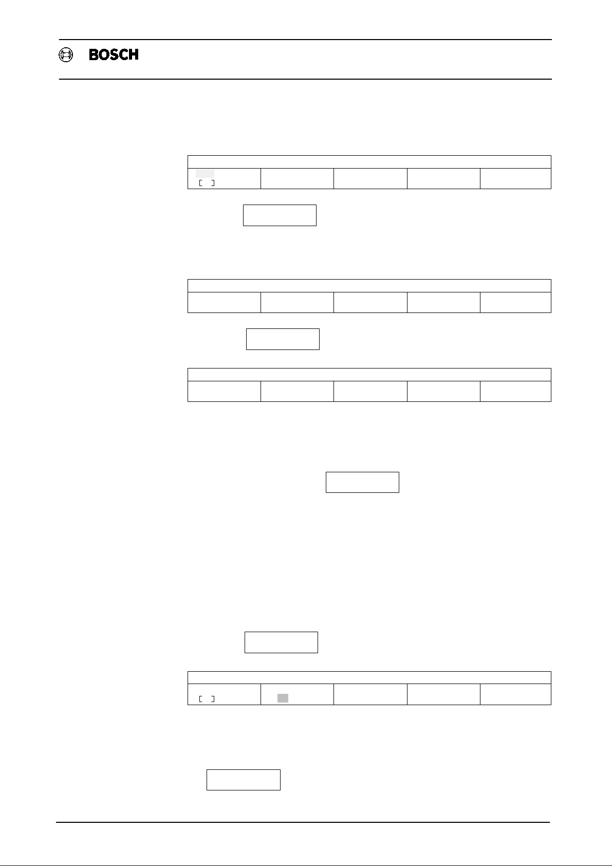
4. Operation
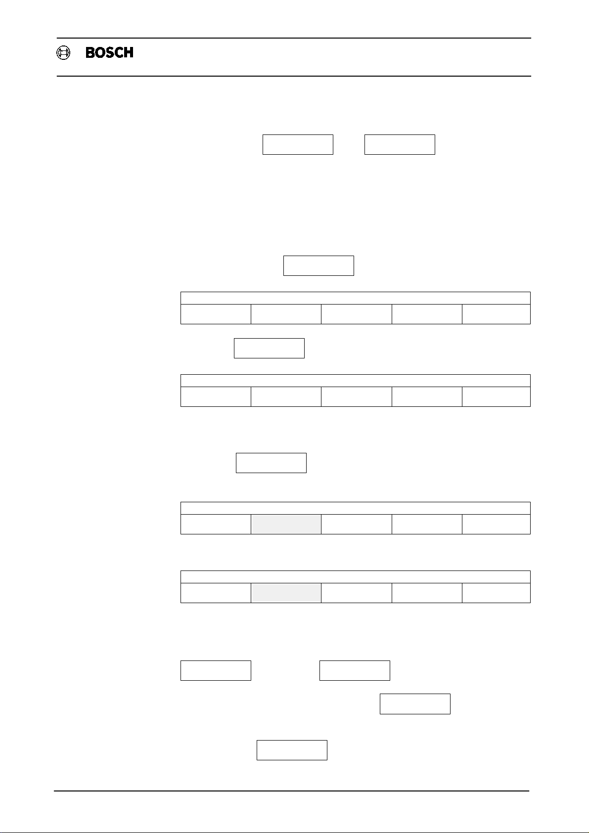
4.1 Running the machine parameters program
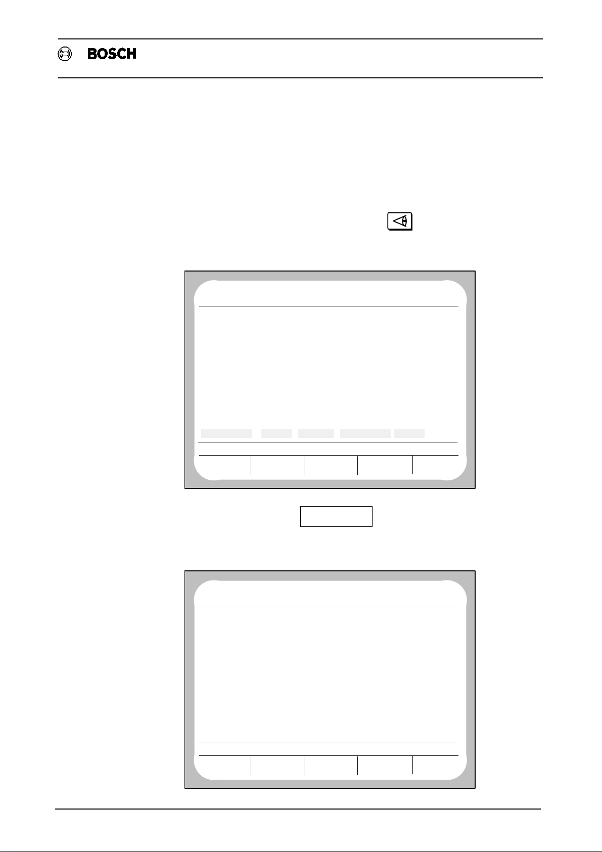
The machine parameters program (MPP) may only be accessed in DIAGNOSTIC
operating mode.
This operating mode is selected by pressing
The following display appears onscreen:
Type1 osa / CC 220
Machine parameters
NO
PROGRAM
ERROR CONDITION ON STATUS
LAST PROGRAMMED
DIAGNOSTIC
CONTROL
BF0
NC0
ACT
WAITING
G
G
G
G
G
G
G
G
G
G
DIAGNOSTIC
MACHINE
G1 G71
G
90
G
94
G
17
G
15
G
153
146
994
80
39
65
130
G
253
G
G
G
115
RESET
FUNCTION
DIAGNOSTIC
24. 3 15:25
66
G
40
G
8
G
29
G
G
G
62
G
68
G
G
140
7
27
79
53
67
97
99
167
SERVICE
FUNCTION
NO REF. POINTS
DRIVES ON
FEED STOP
B 0M 30T 1016S 0F 100.0
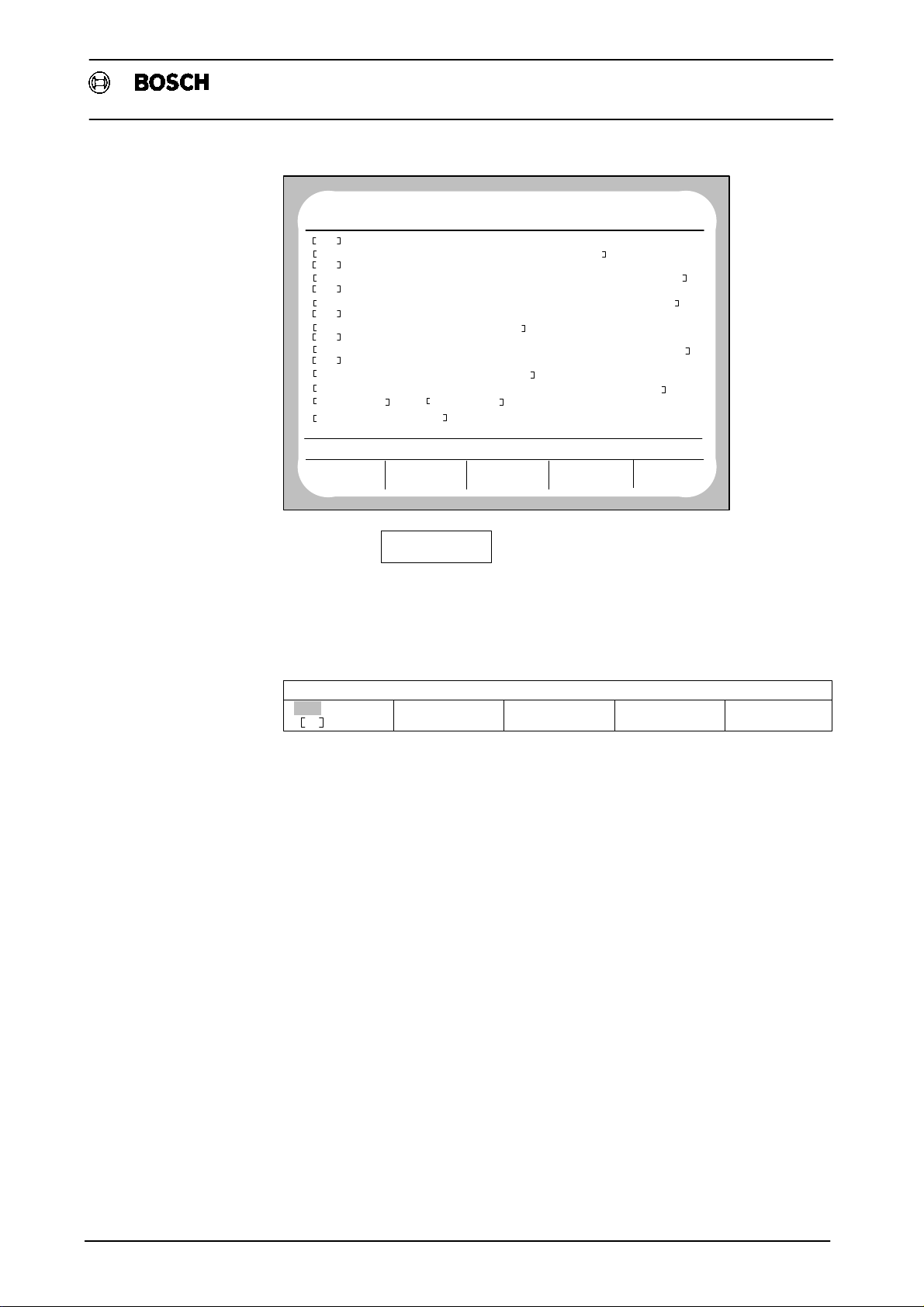
SERVICE
By actuating the softkey
FUNCTION
and − if requested to do so by the
system − inputting a code number, an overview of all currently resident diagnostic
programs (D) may be obtained.
NO
PROGRAM
NUMBER NAME OF PROGRAM LENGTH
D
D
D
D
D
D
D
D
D
D
D
D
MEMORY USED BY DIAGNOSTIC
MEMORY AVAILABLE :
SERVICE FUNCTION
BF0
NC0
ACT
WAITING
1
LOGBOOK MONITOR
2
RELOAD OPERATING PROGRAM
3
CLEAR ALL MEMORY
4
MACHINE PARAMETER PROGRAM
5
INTERNAL REF. POINT OFFSET
6
SERIAL IF DATA
7
COMMUNICATION STORAGE DISPLAY
9
MANAGE EEPROM
21
LOGIC ANALYSER
22
AXIS OSCIL.
23
CONTOUR DISPLAY
24
AXIS OPTIMISATION
4156
185946
LOAD START DELETE
OUTPUT
OTHERS: 72042
− 3 −
DIAGNOSTIC
24. 3 15:25
ACCESS
E
E
E
E
E
E
E
E
E
E
E
E
Page 17

Operation
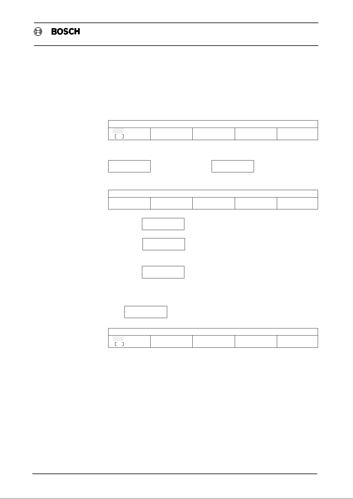
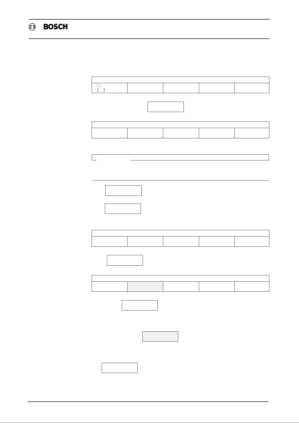
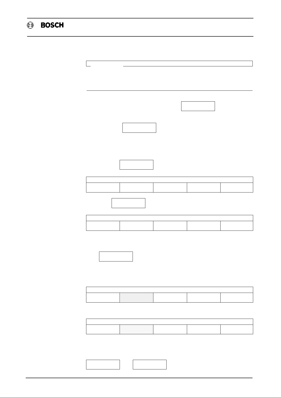
By pressing the softkey
Type1 osa / CC 220
Machine parameters
START
and inputting program number 4, the machine parameter
program may be started.
NO
PROGRAM
NUMBER NAME OF PROGRAM LENGTH
L
L
L
L
L
L
L
MEMORY USED BY SYSTEM
MEMORY AVAILABLE :
MACHINE PARAMETERS PROGRAM
EDIT
BF0
NC0
ACT
WAITING
870
USER<−HEAP<−BLOCK....................
1
NC LINK TABLE
2
NC LINK TABLE
3
NC LINK TABLE
4
NC LINK TABLE
5
NC LINK TABLE
444
MACHINE PARAMETERS 24.03
28219
330307
LOAD OUTPUT MANAGE
TRANSFER
DIAGNOSTIC
24. 3 15:25
ACCESS
4140
RWED
152
RWED
152
RWED
152
RWED
152
RWED
152
RWED
23319
OTHERS: 34690
IMPORTANT
The files NC LINK TABLE" and USER<−HEAP<−BLOCK" have no connection
with the MPP. L444 only appears if the MP has already been edited or output at least
once.
If on selecting DIAGNOSTIC operating mode, the softkey line
DIAGNOSTIC
CONTROL
DIAGNOSTIC
MACHINE
RESET
FUNCTION
SERVICE
FUNCTION
MPP
is displayed, including the MPP" softkey, pressing the softkey
MPP
is all that is needed to reach the Machine parameters program"
operating level.
− 4 −
Page 18

4.2 Editing (modifying)
Operation
Type1 osa / CC 220
Machine parameters
IMPORTANT
Only data which is NOT enclosed in square brackets may be edited!
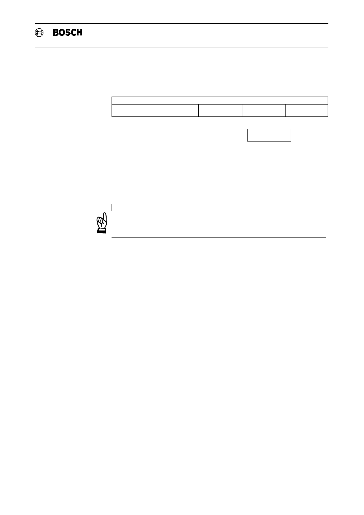
If the parameters are to be edited for the first time, the following display will normally
appear (link tables are only present if programs were linked together beforehand):
NO
PROGRAM
NUMBER NAME OF PROGRAM LENGTH
L
L
L
L
L
L
MEMORY USED BY SYSTEM
MEMORY AVAILABLE :
MACHINE PARAMETERS PROGRAM
EDIT
By pressing the softkey
NO
PROGRAM
NUMBER NAME OF PROGRAM LENGTH
L
L
L
L
L
L
BF0
NC0
ACT
WAITING
870
USER<−HEAP<−BLOCK....................
1
NC LINK TABLE
2
NC LINK TABLE
3
NC LINK TABLE
4
NC LINK TABLE
5
NC LINK TABLE
4900
330307
TRANSFER
EDIT
LOAD OUTPUT MANAGE
BF0
NC0
ACT
WAITING
870
USER<−HEAP<−BLOCK....................
1
NC LINK TABLE
2
NC LINK TABLE
3
NC LINK TABLE
4
NC LINK TABLE
5
NC LINK TABLE
DIAGNOSTIC
24. 3 15:25
ACCESS
4140
RWED
152
RWED
152
RWED
152
RWED
152
RWED
152
OTHERS: 34690
the following operating level is reached
DIAGNOSTIC
24. 3 15:25
ACCESS
4140
RWED
152
RWED
152
RWED
152
RWED
152
RWED
152
MEMORY USED BY SYSTEM
MEMORY AVAILABLE :
MACHINE PARAMETERS PROGRAM
WITH TEXT
4900
330307
WITHOUT TEXT
OTHERS: 58009
By using the soft keys, the L444 machine parameters file can be generated with or
without text. This soft key bar only appears if L444 does not yet exist or has been
deleted.
− 5 −
Page 19

Operation
Type1 osa / CC 220
Machine parameters
After pressing one of the two soft keys, a message appears onscreen indicating
that the file is being generated. The control generates L444 from the default or
application values stored in system memory.
NO
PROGRAM
NUMBER NAME OF PROGRAM LENGTH
L
L
L
L
L
L
MEMORY USED BY SYSTEM
MEMORY AVAILABLE :
PLEASE WAIT: FILE BEING GENERATED, SET 3500
BF0
NC0
ACT
WAITING
870
USER<−HEAP<−BLOCK....................
1
NC LINK TABLE
2
NC LINK TABLE
3
NC LINK TABLE
4
NC LINK TABLE
5
NC LINK TABLE
LOAD OUTPUT MANAGEEDIT
TRANSFER
4900
330307
DIAGNOSTIC
24. 3 15:25
ACCESS
4140
RWED
152
RWED
152
RWED
152
RWED
152
RWED
152
OTHERS: 58009
Once file L444 has been generated, the following display appears:
NO
PROGRAM
OPTIONS
B O S C H CC220 BASIC FUNCTIONS
MEMORY 224 (+32) K−BYTE
CLIENT EPROM 2048 K−BYTE
THREAD CUTTING INCL. G95
THREAD MILLING
FEED FORWARD CONTROL
ACCELERATION PROGRAMMING
LOOP FACTOR PROGRAMMING
CORNER DECELERATION/ACCELERATION
16 STANDARD LIMIT SWITCHES IF
4 FAST LIMIT SWITCHES IF
SOFTWARE LIMIT SWITCHES SUPPRESSED
3 ADDITIONAL AUXILIARY FUNCTIONS
PROGRAMMABLE SPINDLE ORIENTATION
EXTERNAL PROGRAM SELECTION
LEAD SCREW ERROR COMPENSATION
CPL WITH GRAPHIC COMMANDS
DNC INTERFACE WITH SIMPLE PROTOCOL
EDIT
YES NO
$ LF
BF0
ACT
A D G J M
P S V Y
NC0
WAITING
L 444
B E H K N
Q T W Y
C F I L O
R U X
DIAGNOSTIC
24. 3 15:25
FUNCTIONS
All active options are listed before an overview of the machine parameter sets is
displayed.
− 6 −
Page 20

Operation
Example of a machine parameters file (L444) with text
Type1 osa / CC 220
Machine parameters
4.2.1 Input
NO
PROGRAM
MACHINE PARAMETER SETS
P
100
P
500
P
1000
P
1500
P
2000
P
2500
P
3000
P
3500
P
4000
P
4500
P
5000
P
5500
P
6000
P
6100
6200
P
P
6500
EDIT
YES NO
$ LF
BF0
NC0
ACT
WAITING
A X I S P A R A M E T E R S
S P E E D S
A X I S D Y N A M I C S
P O S I T I O N S
A U X I L I A R Y F U N C T I O N S
P O T E N T I O M E T E R S
P O W E R − U P S T A T E
C O L O U R S E T T I N G S
C P L − P A R A M E T E R S
Z E R O S H I F T S
S U P P R E S S I O N T A B L E
D E V I C E S E L E C T I O N
P L C P A R A M E T E R S
E L E C T R: L I M I T S W I T C H N O R M A L
E L E C T R: L I M I T S W I T C H F A S T
T O O L C O M P E N S A T I O N S
L 444
A D G J M
P S V Y
B E H K N
Q T W Y
C F I L O
R U X
DIAGNOSTIC
24. 3 15:25
FUNCTIONS
If there is already a keyboard available (e.g. with Type1 osa keyboard), then
characters are selected via the keyboard (SK:Keyboard available is in reverse
video; see chapter 4.2.5), and the highest level of the editor appears as follows:
EDIT L 444
DELETE SEARCH
POSITION
CURSOR
FUNCTIONS
The softkey bar
EDIT L 444
YES NO
$ LF
A D G J M
P S V Y
B E H K N
Q T W Z
C F I L O
R U X
FUNCTIONS
identifies the highest editor level if no keyboard is available or the softkey
Keyboard available is not in reverse video (see chapter 4.2.5).
At this level, it is possible to input any of the alphabetic characters displayed.
It is possible to insert the softkey character displayed in reverse video into the MP
file by pressing the RETURN key.
By pressing a soft key repeatedly, the characters which can be selected from this
menu are displayed in reverse video one after the other.
The cursor indicates the point at which any characters entered are inserted into the
file.
− 7 −
Page 21
4.2.2 Cursor functions
Operation
Type1 osa / CC 220
Machine parameters
The cursor can be moved anywhere on the screen using the cursor keys. In
addition, the cursor can be placed in certain positions, which must be specified.
Position cursor
Starting at operating level
EDIT L 444
YES NO
$ LF
A D G J M
P S V Y
B E H K N
Q T W Z
C F I L O
R U X
FUNCTIONS
by selecting
FUNCTIONS
and then selecting
POSITION
CURSOR
the operating level is
reached.
EDIT L 444
RETURN BLOCK WORD 8 LINES
BLOCK
By selecting
By selecting
WORD
the cursor always jumps to the start of a new line.
the cursor jumps to the first character of the next
* DOWN
UP
word.
8 LINES
By selecting
the cursor always jumps down 8 lines.
By selecting the down/up" softkey, the cursor functions become effective towards
the end/start of the file.
RETURN
Press
EDIT L 444
YES NO
$ LF
to return to operating level
A D G J M
P S V Y
B E H K N
Q T W Z
C F I L O
R U X
FUNCTIONS
Scroll
The screen display can be scrolled up and down line by line using the cursor keys.
− 8 −
Page 22
4.2.3 Search
Operation
Type1 osa / CC 220
Machine parameters
It is possible to carry out searches for specific individual terms in the editor.
EDIT L 444
YES NO
$ LF
The softkey
FUNCTIONS
A D G J M
P S V Y
B E H K N
Q T W Z
C F I L O
R U X
FUNCTIONS
should be pressed at the highest operating level of
the editor.
This initiates the transition to the next operating level.
EDIT L 444
DELETE SEARCH
By selecting
SEARCH
POSITION
CURSOR
the following display is reached:
FUNCTIONS
EDIT L 444
RETURN
DEFINE
STRING
SEARCH FOR
STRING
END
*DOWN
UP
Direction of search
The direction of search must be determined before specifying the string to be
searched for.
* DOWN
UP
This can be done by pressing
.
The asterisk indicates the active direction.
The softkey END is displayed if search direction DOWN is selected, and allows a
jump directly to the end of MP file L444.
The softkey START appears if search direction UP is active, and allows a jump
directly to the beginning of MP file L444.
The softkey RETURN allows a jump back into the highest level of the editor.
Searching for character strings
DEFINE
STRING
By pressing
the following softkey bar appears:
EDIT L 444 SEARCH FOR : P3500
YES NO
$ LF
A D G J M
P S V Y
B E H K N
Q T W Z
C F I L O
R U X
READY
The character string to be searched for may now be entered. Every single letter
must be confirmed by pressing <ENTER>. Numbers are entered directly via the
appropriate keys and cannot/need not be confirmed by pressing <ENTER>.
The
function initiates the search procedure. The cursor jumps to
READY
the searchedfor location.
− 9 −
Page 23
Operation
Type1 osa / CC 220
Machine parameters
NO
PROGRAM
−62
P3009 FEED COMPENSATION ON/OFF (G64/G65)
−65
P3010 OUTSIDE CORNERS AS A RADIUS OR INTERSECTION (G68(69)
−68
P3011 TOOL TABLE COMPENSATION ON/OFF (G145/G46)
− 146
P3012 FEED FORWARD CONTROL (G114/G115)
− 115
P3013 EXTERNAL ZERO SHIFT ON/OFF (G160/G167)
− 167
P3500 C O L O U R S E T T I N G S
P3501 COLOUR "AREA" (FOREGROUND AND BACKGROUND)
FOREGROUND BLACK BACKGROUND LIGHT BLUE
P3502 COLOUR "SOFTKEY"
FOUND
EDIT
RETURN
BF0
ACT
DEFINE
STRING
NC0
WAITING
L 444
SEARCH
STRING
END
DIAGNOSTIC
24. 3 15:25
*DOWN
UP
SEARCH
STRING
By pressing
the search for the specified search word is
continued in the remaining program text, starting at the current location. The
message STRING NOT FOUND" appears if the soughtfor character string is not
found in the active search direction.
The softkey RETURN can be pressed to jump back to the highest operating level.
EDIT L 444
YES NO
$ LF
A D G J M
P S V Y
B E H K N
Q T W Z
C F I L O
R U X
FUNCTIONS
− 10 −
Page 24

4.2.4 Delete / Undelete
Operation
Type1 osa / CC 220
Machine parameters
Starting at operating level
EDIT L 444
DELETE SEARCH
DELETE
by pressing the softkey
EDIT L 444
RETURN
Pressing the softkey
DELETE
BLOCK
DELETE
BLOCK
POSITION
CURSOR
FUNCTIONS
the following operating level is reached:
DELETE
WORD
DELETE
CHARACTER
*DELETE
UNDELETE
deletes the line in the machine parameters
file at the beginning of which the cursor is positioned. If the cursor is positioned in
the middle of a line, the remainder of the line (after the cursor) is deleted.
DELETE
CHARACTER
Pressing the softkey
deletes the character on which the cursor is
positioned.
DELETE
WORD
Placing the cursor on the first letter of a word and pressing
de
letes the word. The cursor must be positioned on a word.
After deleting a line or character, the procedure can be reversed and the text can be
restored to its original condition (undeleting).
DELETE
*UNDELETE
This is achieved by pressing the
softkey. The softkey bar
changes to
EDIT L 444
RETURN
UNDELETE
BLOCK
UNDELETE
WORD
UNDELETE
CHARACTER
DELETE
*UNDELETE
The last item to be deleted (line, word, character) is always stored in an
intermediate buffer.
By pressing
UNDELETE
BLOCK
or
UNDELETE
CHARACTER
or
UNDELETE
WORD
the contents of this buffer memory (i.e. the last item to be deleted) is inserted back
into the MP file. The cursor indicates the position at which the text will be reinserted.
− 11 −
Page 25
4.2.5 Additional functions
Operation
Type1 osa / CC 220
Machine parameters
Starting at highest editor operating level
EDIT L 444
YES NO
$ LF
and pressing the softkey
EDIT L 444
RETURN ABORT FUNCTIONS
A D G J M
P S V Y
B E H K N
FUNCTIONS
Q T W Z
C F I L O
R U X
twice, the following level is reached
FUNCTIONS
IMPORTANT
If the MP file (L444) is not being edited, an additional softkey is displayed entitled
INSERT FILE. This has no significance for the MP file.
RETURN
Press
Press
to return to the original operating level.
ABORT
to leave the editor. The system ignores all data edited up to
this moment and jumps to the level:
MACHINE PARAMETERS PROGRAM
EDIT LOAD
FUNCTIONS
Select
DELETE
TO EOL
The softkey
TRANSFER
again to switch to operating level:
*M30
INSERT
DELETE
TO EOL
SECTION CALCULATE FUNCTIONS
deletes all characters from the current cursor
OUTPUT MANAGE
position until the end of the line.
(The deleted sequence may be restored via UNDELETE BLOCK").
*M30
INSERT
Ensure that the softkey
is in reverse video. This is the only way to
guarantee that an M30 is automatically positioned at the end of the MP file after
editing. Without the M30 the MP file cannot be transferred to the operating system.
The
function allows the calculation of a numerical value to be
CALCULATE
entered, by using arithmetical operations.
The dot before dash" rule applies. Intermediate results are not stored.
The result appears at the current cursor position if ENTER" is pressed.
− 12 −
Page 26

Operation
SECTION
The
complete areas of the text to be edited.
FUNCTIONS
Press
function makes it possible to select, copy, insert and shift
to reach the next softkey level.
Type1 osa / CC 220
Machine parameters
If the
KEYBOARD
AVAILABLE
CHANGE
WORD
function is in reverse video, then text and numbers are
KEYBOARD
AVAILABLE
RETURN
entered using the keyboard (e.g. Type1 osa keyboard). Text and numbers can also
be entered using the five softkeys if this softkey is not displayed in reverse video.
− 13 −
Page 27
4.3 Transfer
Operation
Type1 osa / CC 220
Machine parameters
By jumping back through the levels from the editor the following operating level
may be reached
MACHINE PARAMETERS PROGRAM
EDIT LOAD
TRANSFER
OUTPUT MANAGE
The edited machine parameters are only transferred to the operating system in the
TRANSFER
form of an internal data record by pressing the
softkey. The
operating system is then restarted. Once the machine parameters have been
transfered, file L444 can be deleted and the appropriate memory area made
reavailable via CONTROL REST". L444 is only required in order to edit or output
the machine parameters.
The machine parameters are not automatically transferred into the EEPROMs on
the memory card. This can only be done by using diagnostic program 9 EEPROM
MANAGEMENT" (see 4.7).
NOTE
The CNC power supply must not be interrupted during transfer of machine
parameters!
Error detection
If an error is detected during the transfer process, the faulty line in the MP file is
displayed onscreen under the message INCORRECT MACHINE PARAMETER",
and the error displayed in reverse video. In addition, an error message appears in
the command line.
The transfer is aborted.
Possible error messages
− Machine parameters are missing:
File L 444, which is to be transferred or deleted, does not exist.
− Invalid application data:
May have been edited by mistake.
Remedy: delete L 444 and read in again/regenerate.
− Memory full:
Not enough memory for L 444.
Remedy: control reset or delete other files + control reset.
− To o many or invalid characters:
A parameter contains more than ten characters or an invalid character.
− Invalid block number:
The previous parameter block may be missing in L 444.
− Invalid value:
A parameter value does not fall within the valid range of values.
− Invalid relationship with block XXX:
Inpermissible parameter combinations.
− Interruption of transfer:
During the transfer, the file is read through" a total of three times. During the
first two passes, the process can be interrupted by changing operating mode
or moving back to another level.
If no error is detected, the operating system is restarted.
− 14 −
Page 28
4.4 Delete
Operation
Type1 osa / CC 220
Machine parameters
By pressing the
edited machine parameters file (L444) is deleted without any further request for
confirmation. The DELETE" function has no effect on machine parameters data
stored in system memory.
4.5 Load (CC 220 / Type1 osa)
Loading with CC 220:
By pressing the softkey
LOAD
*SELECT
DEVICES
The softkey
LOAD, *SELECT DEVICES, V24.2
*INTER
FACE
The transfer rate most appropriate to the device must be selected. The active baud
rate is displayed in reverse video.
*STATUS
*SELECT
DEVICES
*DCR
4800 BAUD
MANAGE
DELETE
and
LOAD
the following operating level is reached:
FILE
NUMBER
SEARCH FOR
DFS FILE
accesses the operating level
*DCR
9600 BAUD
*CCDISK
9600 BAUD
softkeys, the entire
START
*XTRANS
9600 BAUD
*INTER
FACE
By pressing
the interface from which data should be loaded is
selected:
LOAD, *SELECT DEVICES, *INTERFACE
V24. 1
20 MA
V24. 2
*DNC CHANNEL
(Optional)
Pressing return twice restores the original operating level:
LOAD
*SELECT
DEVICES
*STATUS
FILE
NUMBER
SEARCH FOR
DFS FILE
Handshake with V24.1 / 20mA and V24.2
To transfer data with a software handshake, the
*STATUS
and then the
The file is selected by pressing the softkey
*SOFTWARE
CONTROL
should be actuated.
FILE
NUMBER
number 444 (MP file) or by using the cursor to select.
START
and entering the
START
By pressing the
softkey, the transfer of the externally stored
machine parameters file into the CNC is initiated.
− 15 −
Page 29
Operation
Type1 osa / CC 220
Machine parameters
IMPORTANT
If *DEVICE CONTROL is used to read out, *DEVICE CONTROL must also be used
to read in.
At baud rates < 600 only software handshake is permissible.
FILE
NUMBER
The file is selected by pressing the softkey
and entering the
number L 444 (MP file) or by using the cursor to select.
By pressing the
softkey, the transfer of the externally stored
START
machine parameters file into the CNC is initiated.
Loading with the Type1 osa:
LOAD
*SELECT
DEVICES
softkey the following operating level is reached
FILE
NUMBER
SEARCH FOR
DFS FILE
START
accesses the operating level
By pressing the
LOAD
*SELECT
DEVICES
The softkey
LOAD, *SELECT DEVICES, PC CHANNEL
*INTER
FACE
The transfer rate most appropriate to the device must be selected, if V24.1/ 20mA is
selected (see also CC220).
*INTER
FACE
Press
to select the interface from which data should be loaded:
The PC channel enables the program (file) to be loaded from the internal hard disk
of the Type1 osa PC. Loading is possible from a device with a serial interface via the
V24.1 /20mA interface:
LOAD, *SELECT DEVICES, *INTERFACE
V24. 1
20 MA
PC CHANNEL
Pressing return twice restores the original operating level:
LOAD PC CHANNEL
*SELECT
DEVICES
FILE
NUMBER
SEARCH FOR
DFS FILE
Handshake with V24.1 / 20mA
To transfer data with a software handshake, the
*SOFTWARE
CONTROL
softkeys should be actuated.
*STATUS
and
− 16 −
START
Page 30

Operation
Type1 osa / CC 220
Machine parameters
FILE
NUMBER
The file is selected by pressing the softkey
and entering the
number L 444 (MP file) or by using the cursor to select.
By pressing the
softkey, the transfer of the externally stored
START
machine parameters file into the CNC is initiated.
If data are to be transfered from the Type1 osa display to the Type1 osa module, this
Load procedure can be controlled via the Data transfer from PC −> NC"
selection window.
NO
PROGRAM
NUMBER NAME OF PROGRAM LENGTH ACCESS
L
L
File
Path c:\osa1_ap2
DFS Identifier
File: Path selection:
english.txt
MP010296.txt
MEM
MEM
Prog1.txt
Prog2.txt
Prog3.txt
MAC
Prog3.txt
Prog3.txt
E
BF0
NC0
ACT
WAITING
5
NC LINK TABLE
444
MACHINE PARAMETER 24.03
Data transfer from PC −> NC
MP010296.txt
(DFS,L 444,MACHINE PARAMETER 102,RWED)
[..]
[−a−]
[−c−]log2_96.txt
DIAGNOSTIC
24. 3 15:25
152
23319
START
ABORT
RWED
RWED
For a description of the operating sequence, see page 20.
Once all MP data has been transferred or integrated, the machine parameters
should be stored in the EEPROM in nonvolatile form (see 4.3 TRANSFER, or 4.7
MANAGE EEPROM)*
− 17 −
Page 31

4.6 Output (CC 220 / Type1 osa)
After pressing the
selecting devices, baud rates and interfaces as appeared under LOAD (refer to
appropriate heading) are called up.
The files of the Type1 osa module (machine parameters, part programs etc.) can
be saved on the hard disk of the Type1 osa display. Please note the following
sequences for data output:
Output with text
If the machine parameters are stored in control without text, the machine parameter
texts should be generated before they are output for documentation. To do this it
may be necessary to delete L 444 (see also chapter 4.8!) before regenerating with
texts (see 4.2 Editing").
Operation
OUTPUT
Type1 osa / CC 220
Machine parameters
softkey, the same operating levels for
NO
PROGRAM
NUMBER NAME OF PROGRAM LENGTH
D
D
D
D 4 MACHINE PARAMETERS PROGRAM E
D
D
D
D
D
D
D
D
MEMORY USED BY DIAGNOSTIC
MEMORY AVAILABLE :
SERVICE FUNCTION
BF0
NC0
ACT
WAITING
1
LOGBOOK MONITOR
2
RELOADING OPERATING PROGRAM
3
CLEAR ALL MEMORY
5
INTERNAL REF. POINT OFFSET
6
INTERFACE DATA
7
COMMUNICATION STORAGE DISPLAY
9
MANAGE EEPROM
21
LOGIC ANALYSER
22
AXIS OSCIL.
23
CONTOUR DISPLAY
24
AXIS OPTIMISATION
4156
185946
LOAD START DELETE
OUTPUT
OTHERS: 72042
DIAGNOSTIC
24. 3 15:25
ACCESS
E
E
E
E
E
E
E
E
E
E
E
Before the machine parameter program is output, start the diagnostic machine
START
parameter program (softkey
) by either selecting with cursor
keys or entering D4".
− 18 −
Page 32

Operation
Type1 osa / CC 220
Machine parameters
NO
PROGRAM
NUMBER NAME OF PROGRAM LENGTH
L5NC LINK TABLE RWED
L 444 MACHINE PARAMETER 24.03 RWED23319
MEMORY USED BY PROGRAM
MEMORY AVAILABLE :
MACHINE PARAMETERS PROGRAM
EDIT
BF0
NC0
ACT
WAITING
28219
330307
LOAD OUTPUT MANAGE
TRANSFER
OTHERS: 34690
DIAGNOSTIC
24. 3 15:25
ACCESS
152
The actual machine parameter file L444" then appears in the menu. If you press
OUTPUT
the softkey
NO
PROGRAM
L5NC LINK TABLE RWED
L 444 MACHINE PARAMETER 24.03 RWED23319
BF0
NC0
ACT
WAITING
NUMBER NAME OF PROGRAM LENGTH
you will be required to select a file.
DIAGNOSTIC
24. 3 15:25
ACCESS
152
MEMORY USED BY PROGRAM
MEMORY AVAILABLE :
OUTPUT
*SELECT
DEVICES
PC CHANNEL
STATUS
28219
330307
FILE
OTHERS: 34690
Ensure that the correct output interface is preset with the
(see status line above the softkey to check)
FILE
Press the
softkey and select by either using the cursor keys or
entering D4".
− 19 −
SELECT
DEVICES
softkey.
Page 33

Operation
Type1 osa / CC 220
Machine parameters
NO
PROGRAM
NUMBER NAME OF PROGRAM LENGTH
L5NC LINK TABLE RWED
L 444 MACHINE PARAMETER 24.03 RWED23319
MEMORY USED BY PROGRAM
MEMORY AVAILABLE :
OUTPUT
*SELECT
DEVICES
BF0
NC0
ACT
WAITING
28219
330307
FILE NUMBER
STATUS START
444
FILE
OTHERS: 34690
DIAGNOSTIC
24. 3 15:25
152
ACCESS
Data transfer from the control unit (NC) to the hard disk (PC) is called up using the
START
softkey
.
If data in the Type1 osa display are to be stored, the new selection window Data
transfer from NC −> PC" appears:
NO
PROGRAM
NUMBER NAME OF PROGRAM LENGTH ACCESS
L
L
File
Path c:\osa1_ap2
DFS Identifier
File: Path selection:
english.txt
L1.txt
MEM
MEM
Prog1.txt
Prog2.txt
Prog3.txt
MAC
Prog3.txt
Prog3.txt
E
BF0
NC0
ACT
WAITING
5
NC LINK TABLE
444
MACHINE PARAMETER 24.03
Data transfer from NC −> PC
MP010296.TXT
[..]
[−a−]
[−c−]log2_96.txt
DIAGNOSTIC
24. 3 15:25
152
23319
START
ABORT
RWED
RWED
Enter the file name in the upper entry field which the machine parameter program is
to be stored under in on the hard disk, e.g. MP010296.txt" for machine parameters
from 01 Feb. 96, txt ending for text file.
Remember to include a full stop in the file name. The stop should be preceded by a
maximum of 8 characters (no special characters such as . , ; ! ? etc.) and followed
by a maximum of 3 characters.
− 20 −
Page 34

4.7 Manage EEPROM
Operation
Type1 osa / CC 220
Machine parameters
After entering the file name, press the TAB key and keep it pressed down until the
entry position (position currently highlighted by the cursor) is on the START field.
Now start data transfer by pressing the ENTER key. If you do not wish to carry out a
data transfer or you want to use another file name, use the TAB key to reach ABORT
and press the ENTER key.
Once transfer has started, a window appears, indicating which stage the data
transfer is currently at.
If the machine parameters are loaded into the EEPROM of the CP/MEM 5card (CC
220) or the FEPROM of the Type1 osa module, they are safeguarded against loss.
This ensures that even after a power loss (e.g. battery failure), the customerspe
cific machine parameters are still available whenever required.
In the diagnostic" operating mode the softkeys
SERVICE
FUNCTION
and then
START
should be pressed.
Further information may be found in Type1/CC 220/320 Diagnosis, Operation,
Application", order no. 1070 073 305.
After program number 9 (EEPROM management) is entered and confirmed by
pressing ENTER, the CNC carries out CONTROL RESET. The following display
appears:
NO
PROGRAM
LIST OF PROGRAMS FOR OUTPUT
NO
NAME OF PROGRAM IN RAM SAME
0
MEMORY USED IN PROGRAM
MEMORY AVAILABLE :
EDIT
BF0
NC0
ACT
WAITING
MACHINE PARAMETERS YES NO
SELECT
L 444
DELETE COPY
943
26705
OTHERS: 3258
DIAGNOSTIC
24. 3 15:25
EEPROM
PROGR.
All programs in the EEPROM (FEPROM) area are listed.
The IN RAM" column indicates whether the listed files are present in RAM. The
SAME" column shows whether the contents of the file in EEPROM (FEPROM) are
the same as those of the corresponding file in RAM.
− 21 −
Page 35

Operation
EEPROM
PROGR.
Now press the
The following display appears:
Type1 osa / CC 220
Machine parameters
softkey and enter the appropriate code number.
NO
PROGRAM
LIST OF PROGRAMS FOR OUTPUT
NO0NAME OF PROGRAM IN RAM SAME
LANGUAGE ENGLISH
MEMORY USED BY PROGRAM
MEMORY AVAILABLE :
PROGRAM EEPROM
MACHINE
PARAMETERS
BF0
NC0
ACT
WAITING
MACHINE PARAMETERS YES NO
AREA
27648
0
OTHERS: 3258
DIAGNOSTIC
24. 3 15:25
STARTPROGRAM
The softkeys in reverse video indicate the EEPROM (FEPROM) areas to be
programmed. Since only the machine parameters and no tables or programs are
to be transferred in our example, deactivate the softkey PROGRAM AREA (softkey
reverts to normal text).
Programming may then be started via softkey START (softkey now appears in
reverse video). The message PROGRAMMING IS ACTIVE" appears in the
command line while programming is taking place, together with the number of
bytes which have already been transferred to EEPROM. The NC may not be
operated during programming.
The character *" preceding list number 0" indicates that the machine parameters
were transferred to the EEPROM (FEPROM).
Programming is complete when the START" softkey no longer appears in reverse
video. The entire EEPROM memory store is initialised if this programming
procedure is taking place for the first time. This lasts about 5 minutes.
When programming is complete, the display indicates that the status of the
machine parameters in the RAM is the same as that in EEPROM (FEPROM)
(column SAME: YES).
− 22 −
Page 36

Operation
4.8 Management of the machine parameters
The machine parameters program (D4) is stored in the CC 220 control unit’s
EPROM or the Type1 osa module FEPROM area as a program capable of being
run, and can be initiated in DIAGNOSTIC" operating mode. It enables access to
machine parameter data.
A distinction should be made between machine parameter data in the form of an
MP record stored internally in the RAM area and the machine parameters file L444.
Only the values in the MP record determine the behaviour of the control system.
Machine parameters file L444 is only required if machine parameters need to be
edited or, for example, output to or read in from an external storage medium. L444
can always be generated from the currently active MP record (with/without text).
The MP record can only be modified by TRANSFERRING" an appplication file or
machine parameters file L 444.
If a valid MP record, or one which has been adapted to the particular machine, is
active in the control, file L444 is no longer required and can be deleted (thus saving
memory space). Diagnostic program D9 EEPROM MANAGEMENT" uses the MP
record to program the EEPROM (or FEPROM) area. The record is displayed
onscreen in the list of programs to be output" as a file with the number 0" and the
text MACHINE PARAMETERS".
Type1 osa / CC 220
Machine parameters
IMPORTANT
It is also possible to program file L444 into the EEPROM (FEPROM) area. It should,
however, be noted that L444 requires considerably more memory area than the MP
record. This could mean that valuable EEPROM (FEPROM) memory space is
being unnecessarily wasted.
The MP record is located in a RAM area which the user has no access to. By
contrast, the file L444 (if present) is located in the user RAM. If the machine
parameter data is to be edited, the system copies file L444 from user RAM into a
special RAM area, which we will call EDIT memory. Only here can machine
parameters be edited or read in/out.
IMPORTANT
If machine parameters are to be edited when there are not enough free RAM
memory locations, the message MEMORY FULL" is output.
Remedy: Activate Control reset" to gain more free memory space.
−
− 23 −
Page 37

Operation
Type1 osa / CC 220
Machine parameters
− 24 −
Page 38

Overview
Type1 osa / CC 220
Machine parameters
5. Machine parameters
Here you will find the machine parameters for the Ty pe1 osa M / T and CC 220 M / T control unit series. The way in
which individual parameters are displayed will depend on the type of control system used (T or M) and the options
applicable in each case. The values specified for the various parameters correspond to the input values.
Specific information on the SERVO i, SCP, PIC250 control unit series relates to the CC 220 control unit series. Infor
mation on the Typ e1 osa modul 3 / 5 control unit series relates to the Ty p e1 osa control unit series. For explanations
of hardware configuration in the control unit series, refer to the CC 220 Connection conditions part 1" manual and in
the T ype1 osa Connection conditions" manual.
5.1 Machine parameter sets
P 100 AXIS PARAMETERS
P 500 SPEEDS
P 1000 AXIS DYNAMICS
P 1500 POSITIONS
P 2000 AUXILIARY FUNCTIONS
P 2500 POTENTIOMETER
P 3000 POWERUP STATE
P 3500 COLOUR SETTINGS
P 3600 GREYSCALE SETTINGS
P 4000 CPL PARAMETERS
P 4500 ZERO OFFSETS
P 5000 SUPPRESSION TABLE
P 5500 DEVICE SELECTION
P 6000 PLC PARAMETERS
P 6100 ELECTRONIC LIMIT SWITCH NORMAL
P 6200 ELECTRONIC LIMIT SWITCH FAST
P 6300 LASER APPLICATIONS *)
P 6400 TANGENTIAL TOOL CONTROL *)
P 6500 CENTRE PARAMETERS *)
P 6600 COMPENSATION PARAMETERS
P 6800 CONTOURDEPENDENT FEEDRATE OVERRIDE
P 7000 SPINDLE PARAMETERS
P 7100 SPINDLE PARAMETERS 2ND SPINDLE **)
P 7200 EXACT TAPPING
P 7500 TURNING MACHINE **)
P 7600 CAXIS PARAMETERS
P 8500 DNC INTERFACE WITH SIMPLE PROTOCOL***)
P 8600 DNC INTERFACE WITH LSV2 PROTOCOL***)
P 8700 FMS COMMUNICATIONS INTERFACE WITH BAB***)
P 9000 ADDRESS SELECTION
P 9500 AXIS PROCESSORS
P 9900 SYSTEM PARAMETERS
*) only in Type1 osa M and CC 220 M,
**) only in Type1 osa T and CC 220 T
***) only in CC 220 M and CC 220 T
− 25 −
Page 39

Overview
Type1 osa / CC 220
Machine parameters
− 26 −
Page 40

P 100 Axis parameters
P 100 Axis parameters
P 101 No. of axes
[SYN] 3 [ASY] 1
This parameter is used to specify the number of applied system axes to be used as
synchronous/asynchronous axes (depending on option, CC 220: max. 8; Type1
osa: max. 5). The sum of both values should correspond to the total number of axes
in the system.
The spindle is treated as an asynchronous axis and must be taken into account at
this point (analog output as asynchronous axis). At least 2 synchronous axes
must be applied.
P102 Axis addresses (− = not defined)
[1.A] X [2.A] Y [3.A] Z [4.A] −
Type1 osa / CC 220
Machine parameters
The machine parameter allocates logical addresses to the individual system axes
(designated in the machine parameters as [1.A]" to max. [8.A]"). The axes are
then operated via these logical addresses in part programs or CPL programs.
Permissible logical addresses: A−C, E, O, S−Z.
These addresses should not overlap with auxiliary function addresses (see
P 2001) or with polar coordinates’ addresses (P 9909)!
Where an axis is specified as a spindle in parameter 7001, the S" address may
only be allocated to this system axis. However, the spindle address should not be
specified here; a −" is entered in its place. For setting the spindle parameters, see
parameter set 7000.
Always bear in mind that all synchronous axes are specified before the
asynchronous axes in P 102.
IMPORTANT
The individual axes can be allocated different addresses to the ones given for the
screen display. See P 122.
The allocation of the individual system axes to inputs/outputs of the SERVOicards
can be specified via P 9502!
P 103 Axis format postdecimal position Range of values: 0 − 4
[1.A] 3 [2.A] 3 [3.A] 3 [4.A] 3
By means of this parameter, you can specify the postdecimal positions in the
display, as well as the computational accuracy (resolution, increment size). In
parameter set 9000, you can (amongst other things) specify the total number of
digits for every address letter.
Example: Determining the size of increments
0 = 1 Increment = 1 mm
1 = 1 Increment = 1/10 mm
2 = 1 Increment = 1/100 mm
3 = 1 Increment = 1/1000 mm
4 = 1 Increment = 1/10000 mm
− 27 −
Page 41

P 100 Axis parameters
P 104 Measuring system resolution in pulses/rev (0 = linear scale) Range of values: 10 − 8000
[1.A] 1000 [2.A] 1000 [3.A] 1000 [4.A] 1000
The number of strokes of the measuring system encoder (e.g. 1000" at 1000
pulses/rev.) should be entered here. P 104 is used for checking markers, i.e. by
monitoring the pulses between two cyclic reference markings of a rotary encoder.
Enter 0" for the corresponding system axis when using a linear scale or for
encoders with more than 8000 strokes (e.g. for Caxis encoder).
The number of strokes must be entered between two cyclic reference markings for
distancecoded measuring systems. The watchdog on each individual axis can be
switched off if a HIGH level prevails at the axisrelated NC input INHIBIT
MEASURING SYSTEM MONITOR (23.x).
IMPORTANT
The value entered here for the spindle axis must correspond to P7022.
P 105 Measuring system evaluation in pulses/incr. Range of values: 0.025 − 24.000000
Type1 osa / CC 220
Machine parameters
[1.A] 0.500000 [2.A] 0.500000 [3.A] 0.500000 [4.A] 0.500000
The evaluation depends on the number of strokes of the encoder, the leadscrew
pitch, the gearing transmission ratio and the required resolution.
The value entered here for the spindle axis must correspond to the value in P7024.
Calculation formula for linear axis:
No. of strokes x transmission ratio
Lead screw pitch x resolution
Resolutions:
1 m = 1000 Incr./mm]; if P 9904 = MM and P 103 = 3m
10 m =m
100 m =m 10
[
[
Incr./mm]; if P 9904 = MM and P 103 = 2
100
[
Incr./mm]; if P 9904 = MM and P 103 = 1
= Measuring system evaluation
− 28 −
Page 42

P 100 Axis parameters
Examples of calculations for linear axes
Type1 osa / CC 220
Machine parameters
Encoder:
Lead screw pitch:
Resolution:
2500 [pulses/rev]
10 mm/rev x 1000 Incr./mm
[
Encoder:
Lead screw pitch:
Gearing:
Resolution: 1 m = 1000 [Incr./mm]
2500 [pulses/rev] x 5
10 [mm/rev] x 1000 [incr./mm]
Calculation formulae for rotary axes:
When programming in degrees(e.g. C−axis)
No. of strokes pulses/rev
[
360 deg/rev x resolution
2500 [pulses/rev]
[]
10 mm/rev
1 m = 1000 [Incr./mm]
m
]
]
[]
2500 [pulses/rev]
10 [mm/rev]
1 : 5 (transmission ratio)
As the spindle is the driving component and the
encoder the driven part, the encoder rotates
5 times for every time the spindle rotates.
m
[]
fixed coupling spindle/encoder
= 0.25 [Pulses/incr.] Input: 0.25
= 1.25 [Pulses/incr.] Input: 1.25
=
Measuring system evaluation
[]
pulses/incr.
Note:
Parameters P501 − P508 and P511 should be entered accordingly
in degrees, degrees/min. etc.
When programming in revolutions
No. of strokes pulses/rev
Resolution incr./rev
Note:
Parameters P501 − P508 and P511 should be entered accordingly
in degrees, degrees/min. etc.
Resolutions:
[]
1000 Incr./deg
[]
100
Incr./deg if P103 = 2
[]
10
Incr./deg if P103 = 1
P 106 Locking the asynchronous axes or suppressing the spindle display (YES/NO)
[1.A] NO [2.A] NO [3.A] NO [4.A] YES
[]
[]
if P103 = 3
Measuring system evaluation
=
pulses/incr.
[
]
If this parameter was set to YES" for an asynchronous axis, the following functions
may no longer be carried out: jogging, approach reference point, positioning via
the interface (external setpoint input) and largescale screen display formats.
− 29 −
Page 43

P 100 Axis parameters
YES" should always be entered for the spindle axis. NO" must be entered for
ANALOG" type axes.
IMPORTANT
For Caxis: If the spindle axis is separated from the axis of the tool being operated
(P7604 does not equal P7001), NO" must be entered for the corresponding
system axis of the tool.
P 107 Type of axis (ROTARY/LINEAR/ENDLESS/ANALOG)
[1.A] LINEAR [2.A] LINEAR [3.A] LINEAR [4.A] ROTARY
Specifying the type of axis
LINEAR: The axis can only be moved within the travel limit range (see
P 1505 and P 1506). Where there is active suppression of soft
ware limits (P 1504 = YES), the maximum range of motion will be
equal to 2 * 109 increments.
Type1 osa / CC 220
Machine parameters
ROTARY: The axis can only be moved within the travel limit range (see
P 1505 and P 1506). Where there is active suppression of soft
ware limits (P 1504 = YES), the maximum range of motion will be
equal to 2 * 109 increments. The only difference between
ROTARY" and LINEAR" axis types is that LINEAR" axes are
programmed in mm" and ROTARY" axes are programmed in
degrees.
ENDLESS: When programming a single block, endless rotary axes are
treated in the same way as ROTARY" axis types. During a block,
the axis is first moved to its programmed end position. However,
at the end of block a modulo calculation is then carried out (mod
360) on the end position. In this way, the end position (if it lies
outside the limits) 0º x end position t 360º is always changed
back into the range 0º x end position t 360º . This means that
the endless rotary axis can be traversed in one and the same
direction as often as necessary.
ANALOG: In the case of an axis type defined as ANALOG", a voltage pro
portional to the programmed value is output at the analog output
(without measuring system feedback). The maximum value
which can be programmed should be specified in P 501. This
value corresponds to an output voltage of +10V. The output volt
age is adapted rampwise as setpoint values change in accor
dance with the acceleration value stored in machine parameter
P (for example, see P 1002). If an axis was defined as ANALOG",
an axis address must be allocated to this axis in
P 102. Every analog axis must be defined as a synchronous axis
(P 101).
IMPORTANT
If Hirth logic (P 108) is activated for ROTARY" and ENDLESS" axis types and at
the same time parameters are set for the affected axis P 117 by a YES" input, their
positional value in MACHINE operating mode will always be displayed in the range
o=<
0 position value < 360 .
o
− 30 −
Page 44

P 100 Axis parameters
An additive compensation of the axis set position is permitted for the axis type
ROTARY (provided it is not declared as Hirth axis P 108) using the digital
handwheel.
The LINEAR axis type can also be moved endlessly" in one direction. See P 6516
for more detailed explanations and settings (only Type1 osa M / CC 220M).
An external acceleration input (see P1002 ff.) via a wordcoupled PLC is not
effective for the ANALOG axis type.
P 108 Positions per circle for the Hirth axis (0 = no Hirth axis) Range of values: 0 − 360000
[1.A] 0 [2.A] 0 [3.A] 0 [4.A] 0
An input in the range from 1 to 360000 defines the axis concerned as a Hirth axis.
Hirth axes are rotary axes which can take part in interpolation, but may only travel to
certain positions.
P 108 only applies to ROTARY and ENDLESS axis types. The number of positions
which may be approached per
o
is entered here (Hirth logic).
360
Type1 osa / CC 220
Machine parameters
P 108 = 0 no Hirth logic
P 108 u 0 Hirth logic
If 0" is entered, the parameters P 110, P 117, P 119 and P 120 have no effect.
Example:
P 108 = 360 360 approachable positions per revolution
P 108 = 720 720 approachable positions per revolution
IMPORTANT
‘ P 108 may only be set to values greater than 0" in the case of rotary axes
programmed in degrees (not in the case of rotary axes programmed in revo
lutions).
‘ The Hirth axis reference point and limit switch must lie on the Hirth grid.
‘ Hirth axes may not be operated by handwheel or online compensation with
handwheel".
‘ If positions have been programmed which do not lie on the Hirth grid, P 121
should be taken into consideration.
P 109 Currently unused Range of values: 1
[1.A] 1.00 [2.A] 1.00 [3.A] 1.00 [4.A] 1.00
− 31 −
Page 45

P 100 Axis parameters
P 110 Position programming (YES/NO)
[1.A] NO [2.A] NO [3.A] NO [4.A] NO
If a value greater than 0" was input in P 108, it may be specified in P 110 whether
that axis should be programmed in degrees or in positions.
Enter YES" if the axis should be programmed in positions. The axis letter is then
programmed together with the position number (used in the case of tool
magazines, for example).
In this instance the position number 0 always corresponds to the position 0"
degrees.
Example:
Tool magazine (asynchronous axis : A). P 110 = YES, P 108 = 12.
The tool magazine is subdivided into 12 positions (i.e. there are 12 approachable
positions in any one revolution of the axis).
Programming (if P 111 = 2):
N 100 A 7= magazine traverses to position 7 (in positive direction)
N 110 A−6 = magazine traverses to position 6 (in negative direction)
N 120 A 0= magazine traverses to position 0 (in positive direction)
Type1 osa / CC 220
Machine parameters
IMPORTANT
P 110 can also be combined with P 111.
P 111 Hirth programming mode (1, 2, 3, 4)
[1.A] 3 [2.A] 3 [3.A] 3 [4.A] 3
The programming mode of normal" rotary axes, endless axes and Hirth axes can
be defined in P 111.
Entering 1" = programming with search logic"
Entering 2" = programming with +/− sign determines direction"
Entering 3" = programming as for a normal rotary axis
Entering 4" = combination of 2" and 3" (effective only with synchronous rotary
axis)
+
350
1080
720
360
0
o
o
o
o
o
10
370
o
730
20
o
380
o
o
o
−
990o630o270
o
− 32 −
180
540
900
90o450o810
o
o
o
o
Page 46

P 100 Axis parameters
Type1 osa / CC 220
Machine parameters
Search logic: Search logic means that the axis always travels to the pro
grammed position via the shortest route (in relation to the unit
circle) (maximum distance to be traversed =
The actual position equals e.g.
o
. A set position of
350
180
o
).
o
10
then entered. Physically, this position occurs several times for a
rotary axis
10o370o730
, , , 1090
(
o
o
etc.)
. The search logic now se
lects as a set position the physical position which is the shortest
o
distance from the the actual position − in this case
370
. Only
absolute values may be programmed.
A −" sign is ignored by the control.
Any G91 which may be active is not taken into consideration dur
ing this process.
Examples:
Actual position =
N100 A10 axis traverses
350
o
to
370
o
20
o
(in pos. direction)
or N100 A−10 as for A10" (+/− sign is
ignored)
or N100 A180 axis traverses
170
o
to
180
o
(in neg. direction)
or N100 A710 axis does not traverse.
is
+/− sign: The direction from which the set position is approached is en
tirely dependent on the programmed sign (max. traverse path
per record <
o
). If a negative sign is programmed, the axis
360
approaches the set position in negative direction; if the sign is
positive, it approaches in the positive direction (positive signs do
not need to be programmed). The actual position equals e.g.
o
. The value −20" is now programmed. Physically, this
730
position occurs several times for a rotary axis
20o380o740
, , , 1100
( etc.)
o
tive direction to the position corresponding to
o
. Any G91 which may be active is effective for this setting.
380
o
. The axis traverses in nega
o
− in this case
20
Examples:
Actual position =
N100 A10 axis traverses
350
o
20
o
to
370
o
(in pos. direction)
or N100 A10 axis traverses
340
o
to
10
o
(in neg. direction)
or N100 A180 axis traverses
190
o
to
540
o
(in pos. direction)
or N100 A370 axis traverses
340
o
to
10
o
(in neg. direction)
or N100 A350 axis does not traverse
or N100 A710 axis does not traverse.
− 33 −
Page 47

P 100 Axis parameters
Type1 osa / CC 220
Machine parameters
Normal: During programming, the rotary axis behaves like a normal"
rotary axis (ROTARY" axis type).
The conversion to positions between
o
and
0
360
o
at the end
of the record here depends on P 107 (ROTARY/ENDLESS).
Both G90 and G91 have an effect on this type of axis.
Examples:
o
Actual position =
N100 A10 axis traverses
; P 107 = ROTARY; G90 active
350
340
o
to
10
o
(in neg. direction)
or N100 A−10 axis traverses
360
o
to
−10
o
(in neg. direction)
or N100 A180 axis traverses
170
o
to
180
o
(in neg. direction)
or N100 A−370 axis traverses
720
o
to
−370
o
(in neg. direction)
Combined: For absolute programming or ext. setpoint input:
Designate as under sign", where the max. traverse path per re
cord can now equal 360°.
Zero shifts can only be used for synchronous axes with internal
setpoint input (programming).
For incremental programming or ext. setpoint input:
As described under normal".
IMPORTANT
P 111 can also be combined with P 110.
P 112 Setpoint input (INTERNAL/EXTERNAL)
[1.A] INTERNAL [2.A] INTERNAL [3.A] INTERNAL [4.A] INTERNAL
It is possible to enter the setpoint value for synchronous or asynchronous axes
internally (CNC) or externally (PLC) (see also Interface Conditions Part 2, signals
O7.0 to 7.7).
It is not possible to specify the setpoint input from both locations − once in the CNC
and once in the PLC. Exception for external setpoint input: The CNC can output a
value to the interface by means of auxiliary functions. This value is then processed
in the PLC and passed back to the CNC.
P 113 Multi interface data BCD or binary coded (BIN/BCD)
[−] BIN
Certain signals are exchanged at the interface between the CC 220 or Type1 osa
and the interface controller.
The output may be coded in BCD or binary.
In the case of BCD" encoded values the +/− sign is specified via the interface,
whereas in the case of binary" encoded values, the figure must be coded in two’s
complement.
− 34 −
Page 48

P 100 Axis parameters
P 114 Ref. travel after measuring system monitoring block (YES/NO)
[1.A] YES [2.A] YES [3.A] YES [4.A] YES
With the help of parameter P 114 it is possible to specify whether an axis must
approach the reference point after the measuring system monitor block" has been
suppressed. The measuring system of the individual axes can be suppressed
(blocked) by means of interface signals 23.0 to 23.7. The monitoring function can
only be reactivated by resetting the relevant interface signal (23.x).
Example:
P 114 = YES The affected axis must travel to a new reference point.
P 114 = NO Reference point is retained − even if the measuring sys
tem was drawn − in case the axis had already travelled
to the reference point when interface signal 23.x was set.
It is not necessary to program in a new approach to
reference point.
Type1 osa / CC 220
Machine parameters
P 115 Measuring system direction (POSITIVE/NEGATIVE)
[1.A] NEGATIVE [2.A] NEGATIVE [3.A] NEGATIVE [4.A] NEGATIVE
P 116 Servo output polarity (POSITIVE/NEGATIVE)
[1.A] NEGATIVE [2.A] NEGATIVE [3.A] NEGATIVE [4.A] NEGATIVE
Parameters P 115 and P 116 relate to the closed control loop. In this way the system
can if necessary be adapted to the setpoint input without any resoldering.
P 117 Modulo display in MACHINE operating mode
[1.A] NO [2.A] NO [3.A] NO [4.A] NO
If an axis is defined in P 108 as a Hirth axis, the type of display for this axis can also
be defined here, in MACHINE operating mode.
NO: The display value (actual value) may fall outside the limits
o=<
0 display value <360
YES: The display value always falls within the limits
o=<
0 display value < 360
continually transformed by modulo calculation (mod 360) in the
range
o=<
0 X < 360
o
. This type of display is only possible if para
meter P 111 for the axis concerned is set to 1" , 2" or 4".
o
.
o
. For this purpose, the position value is
Example: P 107 = ROTARY; P 108 = 360; P 117 = YES
Actual val. Display
o
72
360
−721
o
o
72.000
0.000
359.000
− 35 −
Page 49

P 100 Axis parameters
P 118 Offset drive in mm or degrees (lag)
[1.A] 0.0000 [2.A] 0.0000 [3.A] 0.0000 [4.A] 0.0000
By means of parameter P 118, the drift" of the system as a whole can be corrected.
The value shown while the axis is stationary in the lag" display in control
diagnostics" mode should be input.
Example:
Lag display: 0.012 mm
Entry: 0.012 mm
IMPORTANT
There is no measuring system feedback for ANALOG" axis types. Thus the lag
display does not show any meaningful values. In this case the offset must be
measured by means of a voltmeter. The following then applies:
Type1 osa / CC 220
Machine parameters
P 118 =
In the axis optimisation" diagnostic program (D24) it is possible to transfer values
found there automatically to P 118.
P 119 Position indication in automatic and manual modes (YES/NO )
[1.A] NO [2.A] NO [3.A] NO [4.A] NO
Parameter P 119 affects the display of end point, actual value, residual distance"
in AUTOMATIC and MANUAL DATA INPUT (MDI) modes.
YES: Indicates the actual position in terms of positions. A modulo calcu
NO: Displays the actual position in degrees. No modulo calculation is
IMPORTANT
NO" must be entered if P 108 > 36000.
P 501 x Offset
10 V
lation is performed on the displayed value if P 111 is set to 1" or 2".
If P 111 is set to 3, the position is indicated without recourse
to a modulo calculation.
performed on the displayed value.
[V]
x (−1)
P 120 Run time error caused by faulty Hirth axis programming (YES/NO)
[−] NO
YES: If the programmed value does not lie exactly on the Hirth grid, a run
time error appears.
NO: If the programmed value does not lie exactly on the Hirth grid, a run
time error is suppressed. The CNC then automatically moves the
axis concerned to the next possible Hirth grid position according to
the programmed value.
IMPORTANT
− 36 −
Page 50

P 100 Axis parameters
The runtime error is effective for synchronous axes only. A runtime error will not
appear with asynchronous axes (entry therefore: NO).
P 121 Display program value (YES/NO)
[−] NO
YES: When the end point, actual value, residual value" display is shown
in AUTOMATIC and MDI modes, the programmed value of an axis is
also displayed (without taking any active corrections into account).
NO: The programmed value is not displayed.
P 122 Axis address for display (Range of values: characters A" to Z", *" and −")
[1.A] * [2.A] * [3.A] * [4.A] *
Type1 osa / CC 220
Machine parameters
Using this parameter, an address character for the axis display on the CNC
screen can be allocated to each axis independently of P 102 (e.g. for the display of
slave axes).
This possibility is significant if, for example, the position entry for an external axis
needs to be retained by the PLC. In this case, the position would have to be
transferred in the part program to the PLC, e.g. by means of auxiliary function O".
However, an axis with address O" should be defined in P 102 at the same time, in
order to maintain a clear allocation between the axis position programmed in the
part program and the axis display on the screen.
The definition of an auxiliary function address is only permissible, though, if this
address is not being used for other purposes (e.g. in P 102)! P 122 offers a way
around this problem.
Possible inputs:
*": The axis address is displayed, as defined in P 102.
−": The corresponding axis address is not displayed on the screen.
A" to Z": The corresponding axis is displayed on the screen under the ad
dress characters entered here; even if this axis was defined in P
102 with no address or a different address.
Examples:
P 102: [1.A] X [2.A] Y [3.A] Z [4.A] −
P 122: [1.A] * [2.A] * [3.A] * [4.A] O
Axes 1−3 are displayed under the addresses X, Y and Z, the 4th
axis under address O".
P 102: [1.A] X [2.A] Y [3.A] Z [4.A] U
P 122: [1.A] * [2.A] Z [3.A] Y [4.A] B
Display: 1st axis:X; 2nd axis:Z; 3rd axis:Y; 4th axis:B
P 123 Display of auxiliary functions in line 22 (0=OFF)
(Range of values: 0−3 or 0−6, depending on number of parameters under P 2001)
− 37 −
Page 51

P 100 Axis parameters
[1.] 0 [2.] 0
In addition to the display of F and S auxiliary functions in line 21 in group operating
modes MACHINE, NC (AUTOMATIC) and MDI, a further two auxiliary functions can
be displayed in line 22.
The numbers of the auxiliary functions to be displayed must be entered in P 123
(see example). Entering 0" deactivates this function.
Example:
The following auxiliary functions are defined in P 2001: [1.] [2.] S [3.] T
If the auxiliary functions M and T are now displayed in line 22
[1.] 1 [2.] 3 must be entered in P 123.
If the auxiliary functions M and S are displayed in line 22
[1.] 1 [2.] 2 must be entered in P 123.
IMPORTANT
If auxiliary functions are permanently displayed in line 22, the display of axis
positions in group operating mode MACHINE is switched to small display as soon
as six axes (and not seven axes) are present.
Type1 osa / CC 220
Machine parameters
P 124 Coupled axes (1−3 = 1st axis pair, 3−4 = 2nd axis pair)
(Range of values: 0 to the maximum number of synchronous axis present in the system.
[1.] 0 [2.] 0 [3.] 0 [4.] 0
Two synchronous axes may be coupled together in software fashion via the
G function 995.
Specify which synchronous axes are to be coupled using P 124. A maximum of two
axis pairs can be defined (see example).
Example:
Six synchronous axes are defined in the system (1st axis=X, 2nd axis=Y,
3rd axis=Z, 4th axis=U, 5th axis=V, 6th axis=W).
The U axis is to be coupled with the X axis and the V axis is to be coupled with the
Y axis:
Input in P 124: [1.] 1 [2.] 4 [3.] 2 [4.] 5
IMPORTANT
If an axis coupling is declared in P 124, the axis coupling is activated via the
G function (G 995). If an axis coupling has not been declared, axis coupling is
possible via interface. These two types of coupling are mutually exclusive.
− 38 −
Page 52

P 500 Speeds
Type1 osa / CC 220
Machine parameters
P 500 Speeds
IMPORTANT
Depending on the specifications in P 105 and P 107, parameters P 501 to P 505
should be entered in m/min or 1000 degrees/min:
P 501 Max. feedrate in m/min, 1000 degrees/min Range of values: 0.001 − 99.999
[1.A] 10.000 [2.A] 10.000 [3.A] 10.000 [4.A] 10.000
The maximum feedrate determines the maximum velocity of the axes (rapid feed
G0). The value in P 501 must be x the value in P 508. If an axis is defined as a
spindle, the value for the max. feedrate must correspond to the max. spindle
speed.
Example:
Linear axis: 10.000 − max. feedrate of 10 m/min
Rotary axis: 1.800 − max. feedrate of 5 rpm (
Analog axis: 3.000 − max. voltage of 10V is output if the value 3" is pro
grammed in at the relevant analog output.
1800
o
/min)
IMPORTANT
The range of values for asynchronous axes is dependent on P 103.
P103 Range of values
1, 2
3
4
0.001 −
0.001 −
0.001 −
1000.000
300.000
99.999
The following generally applies for Type1 osa M / CC 220 M:
The maximum axis feedrate possible is limited for P 103=0,1,2,3 to 150 m/min. The
maximum feedrate remains at 200 m/min. This results in the following for the
parameter P 501:
P 501 [x.A] 0.001−150.000 m/min
P 502 Ref. point speed in m/min or 1000 deg/min Range of values: 0.001
[1.A] 10.000 [2.A] 10.000 [3.A] 10.000 [4.A] 10.000
P 502 specifies the maximum speed at which the axes approach the reference
point. This speed is only effective in the following cases:
‘ repeated approach to a reference cam or
‘ always for a distance coded measuring system. The CNC calculates the max.
permissible speed. If the input in P 502 is greater, the internally calculated
speed will be effective.
<
P 1006
=
− 39 −
Page 53

P 500 Speeds
IMPORTANT
− It can be determined, using the interface signals REDUCTION ACROSS
(O4.0 − O4.7), whether the speed under P 502 should be effective during the
first reference point approach.
− G0 feederate is used internally.
P 503 First reduction in reference point speed in m/min or 1000 deg/min
Range of values: 0.001 − 99.999
[1.A] 0.500 [2.A] 0.500 [3.A] 0.500 [4.A] 0.500
By means of parameter P 503, the initial reduced speed at which the axis travels
between the reference cam and the zero mark is specified. Using the IF signals
REDUCTION ACROSS (A4.0 to A4.7), specify whether the speed P 502 or P 503
applies for the first reference point approach.
Recommendation:
Should be 1/20 of the value of P 502!
Type1 osa / CC 220
Machine parameters
P 504 Second reduction in reference point speed in m/min or 1000 deg/min
Range of values: 0.001 − 99.999
[1.A] 0.200 [2.A] 0.200 [3.A] 0.200 [4.A] 0.200
The second speed reduction is determined in parameter P 504. It becomes active
after overrunning the zero reference mark in the reference point.
Recommendation:
Should not be greater than P 503!
IMPORTANT
Parameters P 503 and P 504 have no significance where a distancecoded
measuring system is employed.
P 502 or
P 503
V
ref
P 503
V
1. Red
Zero marker
V
2. Red
Ref. cam
− 40 −
Page 54

P 500 Speeds
P 505 to P 508 Parameters 505, 506, 507 and 508 specify the maximum manual feedrates (Slow",
Medium", Fast" and Highspeed") which take effect for synchronous and
asynchronous axes in orientation mode.
P 505 Manual feed Slow m/min, 1000 deg/min Range of values: 0.001 − 99.999
[1.A] 0.100 [2.A] 0.100 [3.A] 0.100 [4.A] 0.100
IMPORTANT
− The range of values 0.001 − P 501 applies for asynchronous axes.
− Definable speed values can also be transferred from the PLC via
the CNC multi interface for synchronous and asynchronous axis!
P 506 Manual feed Medium m/min, 1000 deg/min Range of values: 0.001 − 99.999
[1.A] 1.000 [2.A] 1.000 [3.A] 1.000 [4.A] 1.000
IMPORTANT
The range of values 0.001 − P 501 applies for asynchronous axes.
Type1 osa / CC 220
Machine parameters
P 507 Manual feed Fast m/min, 1000 deg/min Range of values: 0.001 − 99.999
[1.A] 5.000 [2.A] 5.000 [3.A] 5.000 [4.A] 5.000
IMPORTANT
The range of values 0.001 − P 501 applies for asynchronous axes.
P 508 Manual feed High−speed m/min, 1000 deg/min Range of values: 0.001 − 99.999
[1.A] 10.000 [2.A] 10.000 [3.A] 10.000 [4.A] 10.000
IMPORTANT
The range of values 0.001 − P 501 applies for asynchronous axes.
P 509 Variable increment step Range of values: 1 − 1000000
[1.A] 1000 [2.A] 1000 [3.A] 1000 [4.A] 1000
Parameter P 509 specifies a variable incremental dimension for each axis. If the
step size selection switch of the setup operating panel is in N incr. position, the axis
traverses according to the increment number defined here when the Jog key is
actuated.
The increment size depends on the resolution of the axis concerned.
P 510 Manual feed Fast (G95) in mm/rev Range of values: 1 − 500
[1.A] 100 [2.A] 100 [3.A] 100 [4.A] 100
Parameter P 510 specifies Fast" manual feed in mm/rev which takes effect in
orientation mode.
The values for the Medium" and Slow" feed ranges are generated automatically
by the system. The Medium" feedrate amounts to 10% of the Fast" feedrate; the
Slow" feedrate is 1% of the Fast" feedrate.
− 41 −
Page 55

P 500 Speeds
P 511 Max. path speed in m/min Range of values: 0.001 − 200.000
[−] 10.000
This parameter sets a limit on the programmed feedrate value.
IMPORTANT
The path speed is the sum of the axis speed vectors involved in the tool path. The
path speed may therefore be greater than the maximum highspeed feedrate of
any one individual axis.
P 512 Feedrate limit via interface in m/min Range of values: 0.000 − 200.000
[−] 0.000
The current path speed is set to the maximum permissible snychronous path
speed specified in this machine parameter if the PLC interface O27.6 is HIGH. Once
the IF signal is detected, the feedrate limit becomes effective in the active block.
Type1 osa / CC 220
Machine parameters
IMPORTANT
P 512 must be less than or equal to P 511 (max. feedrate value)!
If feedrate limitation is active, the feedrate potentiometer is only effective up to the
set feedrate value:
Example: P 511 max. feedrate value = 10.000 m/min
P 512 feedrate limitation = 5.000 m/min
The feedrate potentiometer is only effective in the range 0% to 50% if
O27.6 = HIGH
Feedrate limitation is not effective where asynchronous movements (jogging,
referencing,...) are involved.
− 42 −
Page 56

P 1000 Axis dynamics
Type1 osa / CC 220
Machine parameters
P 1000 Axis dynamics
P 1001 Nominal loop gain factor in (m/min)/mm or (1000 degrees/min)/degrees
Range of values: 0.01 − 20.00
[1.A] 1.00 [2.A] 1.00 [3.A] 1.00 [4.A] 1.00
The loop gain factor must be entered for each applied axis in this parameter field.
To ensure definition in path operation with several axis, the same loop gain values
must be entered for all axis taking part on one interpolation.
For this purpose the drives must first be adjusted to 10V. The loop gain factor for
each axis can then be calculated using the following formulae and entered into
P 1001.
Linear axis: Rotary axis:
max. axis feedrate
LF =
lag
IMPORTANT
The loop gain value input via the machine parameter can be altered by calling a
G function (G14) if the loop gain programming" option is applied.
[mm]
[m/min]
max. axis feedrate
KV =
lag degrees
[]
o
[]
1000 /min
IMPORTANT
If feedforward is active, the parameter P 1021 instead of P 1001 is used for the
nominal loop gain factor.
CAUTION!
It is extremely important with regard to the axis behaviour of the machine that the
!
values are carefully determined and entered, since several options of P 1001 con
trol are used to calculate various data.
A maximum of 2 decimal places may be programmed, although some versions of
the machine parameters program allow 3 decimal spaces!
P 1002 Slope acceleration in
[1.A] 0.500 [2.A] 0.500 [3.A] 0.500 [4.A] 0.500
Parameter 1002 determines the maximum acceleration of the individual axes
which can be entered from the interpolator (can be exceeded by the setpoint
output if necessary!).
P 1002 =
This parameter can be changed within a program by using G6. The limit values of
G6 are specified in parameters 1008 and 1009 (for synchronous axes only).
2
m/s
or. 1000 deg/s2 Range of values: 0.001 − 99.999
P 501
60 x acceleration time
[s]
IMPORTANT
− If feedforward control is active, parameter P 1020 is used for slope
acceleration instead of P 1002, as long as other values have not been
specifically programmed (via G6) !
− In the case of an ANALOG" axis type, the following applies:
P 1002 =
P 501
60 x T
[sec]
− 43 −
T = rise time from 0V to 10V of
voltage at analog output
Page 57

P 1000 Axis dynamics
IMPORTANT
The slope acceleration values of P 1002 are overwritten by an external
acceleration input (via a wordcoupled PLC). The external acceleration values
apply only to asynchronous traverse movements (with external setpoint input; see
also P 112) and are modally effective (no deletion after control reset). The slope
acceleration values of P 1002 do not become effective until the PLC has transmitted
a 0 or the control unit is in powerup state or after Clear logic" or hardware reset.
During jogging or referencing, only the preset accleration values of P 1002 are
effective.
P 1003 Slope point automatic mode in m/min or 1000 deg/min
Range of values: Type1 osa T / CC 220 T: 0 − 99.999
Type1 osa M / CC 220 M: 0 − 150.000
[1.A] 0.000 [2.A] 0.000 [3.A] 0.000 [4.A] 0.000
Type1 osa / CC 220
Machine parameters
Parameter 1003 defines the speed (slope point) for each axis for continuous path
operation (AUTOMATIC) during the acceleration or deceleration phases (see the
axis dynamics" diagram).
This slope point is not only effective for block transitions (e.g. as P 1007), but at
any time. When accelerating or braking there is always a speed jump in speed
range 0 to P 1003.
The speed jump during acceleration (0 to P 1003) or braking (P 1003 to 0) is
effective with interpolation modes G8, G9 and G108 (look ahead).
IMPORTANT
If the feedforward control" option is active (see P 1014 to P 1017 and P 3012),
P 1003 should be set to 0.
The following max. slope point applies for Type1 osa M / CC 220 M:
0.000 <= P 1003 <= 99.999 see above,
where 99.999 < P 1003 <= 150.000, P 1003 also has to be less than or equal to
P 501 (max. feedrate).
The slope point must be smaller than the commutation point.
P 1004 Slope point jog mode in m/min or 1000 deg/min Range of values: 0 − 99.999
[1.A] 0.000 [2.A] 0.000 [3.A] 0.000 [4.A] 0.000
Parameter 1004 defines the velocity point (slope point) for each axis in jogging
mode (orientation) (see the axis dynamics" diagram).
Example:
If, for example, a value of 2 [m/min] is entered in P 1004 for an axis, the velocity of
the axis jumps from 0 m/min to 2 m/min when it starts up. Subsequently, it behaves
under controlled acceleration until it reaches its programmed speed.
− 44 −
Page 58

P 1000 Axis dynamics
Under continuous deceleration, it behaves in the same way until it reaches an axis
velocity of 2 m/min. From this speed, the axis is brought to a standstill by a jump in
velocity down to 0 m/min.
IMPORTANT
The range of values 0 − P 501 applies for asynchronous axes.
P 1005 Commutation acceleration in
[1.A] 0.100 [2.A] 0.100 [3.A] 0.100 [4.A] 0.100
Parameter 1005 specifies the acceleration affecting the commutation point (see
P 1006 and axis dynamics" diagram).
P 1005 must be less than P 1002.
IMPORTANT
The commutation acceleration values of P 1005 are overwritten by an external
acceleration input (via a wordcoupled PLC). The external acceleration values
apply only to asynchronous traverse movements (with external setpoint input; see
also P 112) and are modally effective (no deletion after control reset). The
commutation acceleration values of P 1005 do not become effective until the PLC
has transmitted a 0 or the control unit is in powerup state or after Clear logic" or
hardware reset. During jogging or referencing, only the preset accleration values
of P 1005 are effective.
Type1 osa / CC 220
Machine parameters
2
m/s
or 1000 deg/s2 Range of values: 0.001 − 99.999
P 1006 Commutation point in m/min or 1000 deg/min Range of values: 0.000 − 99.999
[1.A] 40.000 [2.A] 40.000 [3.A] 40.000 [4.A] 40.000
Parameter 1006 specifies the commutation point (see axis dynamics" diagram).
The commutation point marks a change in accelerative behaviour and conse
quently serves the adjustment of the characteristic curve of the motor used.
IMPORTANT
G8
The maximum feedrate for G8 is limited by the commutation point.
The following generally apply for Type1 osa / CC 220 M:
The maximum axis feedrate possible is limited for P103=0,1,2,3 to 150 m/min. This
results in the following for parameter P1006:
P1006 [x.A] 0.001 − 150.000 m/min
− 45 −
Page 59

P 1000 Axis dynamics
Type1 osa / CC 220
Machine parameters
P 1007 Max. change in feedrate in m/min or 1000 deg/min Range of values: 0.000 − 99.999
[1.A] 2.000 [2.A] 2.000 [3.A] 2.000 [4.A] 2.000
Parameter 1007 limits valid jumps in feedrate for the individual axes to a maximum
upper limit which may occur in continuous path slope operation (G8 or G108,
G109, G110) at transitions from block to block (see Axis dynamics" diagram, fig.
2).
IMPORTANT
If feedforward control is active, the parameter P 1022 is used for the max. change
in feedrate instead of P 1007.
If G9 is active then P 1007 has no meaning.
Axis dynamics
V
prog.
[m/s]
P 1003
P 1004
P 1006
P 1002
P 1005
Figure 1
t [s]
Y
= V
Workpiece
contour
0
V
y
0
V
x
P1007
P1007
= V
actual
Ideal
X
t
V
Path
0
0
1st block 2nd blockBlock
transition
t
t
Figure 2
− 46 −
Page 60

P 1000 Axis dynamics
Type1 osa / CC 220
Machine parameters
2
P 1008 Minimum programmable slope acceleration in
[1.A] 0.010 [2.A] 0.010 [3.A] 0.010 [4.A] 0.010
P 1008 limits the programmable downward acceleration of an axis with G6. This
limitation also applies for external slope acceleration inputs for synchronous and
asynchronous axes with asynchronous traverse movements from a wordcoupled
PLC (via communication memory).
P 1009 Maximum programmable slope acceleration in
[1.A] 10.000 [2.A] 4.000 [3.A] 0.010 [4.A] 0.010
P 1009 limits the programmable upward acceleration of an axis with G6. This
limitation also applies for external slope acceleration inputs for synchronous and
asynchronous axes with asynchronous traverse movements from a wordcoupled
PLC (via communication memory).
P 1010 Min. loop gain factor in (m/min)/mm or (1000 deg/min)/deg Range of values: 0.01 − 20.00
[1.A] 0.10 [2.A] 0.10 [3.A] 0.10 [4.A] 0.10
Parameter P 1010 specifies the minimum permissible loop gain value with which
G14 can be programmed.
m/s
or 1000 deg/s
2
m/s
or 1000 deg/s2
Range of values: 0.001 − 99.999
Range of values: 0.008 − 99.999
2
P 1011 Max. loop gain factor in (m/min)/mm or (1000 deg/min)/deg Range of values: P 1010 − 20.00
[1.A] 20.00 [2.A] 20.00 [3.A] 20.00 [4.A] 20.00
Parameter P 1011 specifies the maximum permissible loop gain value with which
G14 can be programmed.
P 1012 Lag limit under zerospeed control in mm Range of values: P 1508 − 99.000
[1.A] 1.000 [2.A] 1.000 [3.A] 1.000 [4.A] 1.000
Zerospeed control is a function for monitoring the measuring system. After a delay
(P 1013), it checks whether the axis lag exceeds the limiting value specified in P
1012. If it is exceeded the following error message is output: AXIS MONITORING.
The delay is used to suppress the lag after interpolation has been terminated.
A new setpoint input by the interpolator cancels the monitoring function.
IMPORTANT
‘ The zerospeed control does not work for spindle and analog output or
powered tools.
‘ In the event of a fault (axis lag at rest is too great) you should check the
following possible causes:
− Excessive axis drift (carry out offset calibration adjustment)
− Measuring system is not issuing any pulses (remedy: check measuring
system)
The error is cleared by CONTROL RESET.
‘ The zerospeed control can be switched off in parameter 1013 by inputting
0" for each separate axis individually.
P 1013 Waiting time for zerospeed control in sec (0=off) Range of values: P 9901 − 99.000
− 47 −
Page 61

P 1000 Axis dynamics
[1.A] 0 [2.A] 0 [3.A] 0 [4.A] 0
See P 1012.
P 1014 Max. feedforward speed coefficient Range of values: 0 − 11000
[1.A] 0 [2.A] 0 [3.A] 0 [4.A] 0
P 1014 specifies the upper limiting value of the feedforward speed coefficient,
which can be programmed with G114.
IMPORTANT
‘ The machine parameter only works for applied feedforward control.
‘ For general information on feedforward control, see the programming
guide.
P 1015 Max. feedforward acceleration coefficient Range of values: 0 − 100000
Type1 osa / CC 220
Machine parameters
[1.A] 0 [2.A] 0 [3.A] 0 [4.A] 0
P 1015 specifies the upper limiting value of the feedforward acceleration
coefficient, which can be programmed with G114.
IMPORTANT
‘ The value entered should be lower than or equal to
(P 501/(P 1020 *0.0006))!
‘ The machine parameter only works for applied feedforward control.
‘ For general information on feedforward control, see the programming
guide.
P 1016 Feedforward speed coefficient Range of values: 0 − 11000
[1.A] 0 [2.A] 0 [3.A] 0 [4.A] 0
The feedforward control value for each synchronous axis can be calculated from
the command speed and command acceleration, weighted in each case by an
adjustable variable. The weighting factor for the speed can be specified in P 1016.
IMPORTANT
‘ The value entered must be lower than or equal to P 1014.
‘ The machine parameter only works for applied feedforward control.
‘ For general information on feedforward control, see the programming
guide.
P 1017 Feedforward acceleration coefficient Range of values: 0 − 100000
[1.A] 0 [2.A] 0 [3.A] 0 [4.A] 0
The feedforward control value for each synchronous axis can be calculated from
the command speed and command acceleration, weighted in each case by an
adjustable variable. The weighting factor for the acceleration can be specified in
P 1017.
− 48 −
Page 62

IMPORTANT
‘ The value entered must be lower than or equal to P 1015.
‘ The machine parameter only works for applied feedforward control.
‘ For general information on feedforward control, see the programming
guide.
P 1018 and P 1019 − Explanations
P 1018 and P 1019 control the path monitor" function. This function is responsible
for stopping sychronous and asynchronous axes in all operating modes at the
earliest possible moment if their movement is hindered (e.g. by collisions, tool
breakage). In this way, for example, damage to the torque clutch in case of tool
breakage can be avoided.
The lag of each individual axis is permanently monitored. If the value of the lag of an
axis exceeds a specified limit and is not at least partially reduced within a position
controller cycle (P 9901), the control recognises that the axis is obstructed, stops
the traversing movement by cancelling the signal READY 2 and displays a P2 error
with the corresponding axis address on the panel.
P 1000 Axis dynamics
Type1 osa / CC 220
Machine parameters
The limit value (or limit curve) of the lag is adjustable via machine parameters and
must be determined so that no error arises during normal axis movement
(acceleration/braking phases with/without slope, circular interpolation, rapid
traverse, etc.). The monitor must be able to respond quickly enough in case of
error.
Parameters 1018 and 1019 are used to define this limit curve. A constant share and
a variable (velocity dependent) share may be input.
It is necessary to adjust the constant share of the limit curve because otherwise the
monitor would respond to every small axis movement during standstill. The
constant share of the lag is adjusted via parameter P1018 in increments. Entering
0" deactivates path monitoring for the corresponding axis.
The variable share of the limit curve is proportional to the repective active
command velocity (at constant velocities). The relationship is as follows:
Variable share = (Max. permissible lag / V
A factor can be entered in P1019 which can obstruct the reaction of path monitoring
within specified tolerance limits, even if the maximum permissible lag (which only
applies for constant speed) is exceeded (see example). This is particulary
applicable to traversing phases with inconstant speed (e.g. slope etc.).
max
) * V
set
− 49 −
Page 63

P 1000 Axis dynamics
Lag during normal traversing Lag with tool breakage
Lag
Lag limit curve
Lag
Type1 osa / CC 220
Machine parameters
Limit curve
P1018
Start of traversing movement
End of traversing movement
Time
P1018
T0T
T0: Moment of tool breakage
T
: Path monitor response
1
1
Time
Example for one axis:
Maximum permissible lag at axis standstill: 0.003 mm (=3 inc.)
Maximum axis speed for machine: 10 m/min
Maximum permissible lag with constant V
Maximum permissible lag with inconstant V
: 0.3 mm (=300 inc.)
max
: 0.6 mm (=600 inc.)
max
Input maximum permissible lag at axis standstill in P1018, Increments".
Then calculate the variable share of the limit curve for the maximum axis speed
using the formula:
Variable share = (300 inc. / 10 m/min) *10 m/min = 300 inc.
Since a lag of, for example, 600 inc. can build up at inconstant speed with this
machine, enter the value 2" in P1019 (P 1019 = max. permissible lag with
inconstant V
/ variable share). Ensure that the width of the tolerance band
max
defined in P1019 in this way is dependent on the actual traversing speed! This
means that with an set axis speed of, for example, 1 m/min with otherwise equal
input values, the variable share of the limit curve decreases to 30 increments.
Therefore the path monitor responds at this speed to a lag of 30 inc. * P1019 =
60 inc.
Note on setting:
The value selected for P1019 should not be too large, so that the path monitor can
also respond at high speeds.
The value selected for P1018 should not be too small, so that the path monitor does
not respond immediately at low speeds (owing to the decreasing influence of
P1019).
The following values are sufficient for small test motors with a loop gain factor of 1:
P 1018 = 10 inc. and P 1019 = 1.8 to 2.0.
P 1018 Contour monitoring offset in mm Range of values: 0 − 100000
[1.A] 0 [2.A] 0 [3.A] 0 [4.A] 0
See above: Explanations.
P 1019 Contouring monitoring tolerance band
Range of values: 0.000 − 10.000
[1.A] 10.000 [2.A] 10.000 [3.A] 10.000 [4.A] 10.000
See above: Explanations.
− 50 −
Page 64

P 1000 Axis dynamics
P 1020 to P 1022 − Explanations
The dynamic response of the machine tool axes changes when Feedforward
control" is activated (feedforward control parameters: see P1014 to P1017 and
P3012). This means that the normal" parameters for nominal loop gain, slope
acceleration and max. change in feedrate (P1001, P1002 and P1007) are no longer
properly adjusted. Programs with as well as without activated feedforward control
− with the respective optimal axis dynamics parameters − are to be run on the
machine tool. For this reason, parameters P1020 to P1022 are effective with active
feedforward control instead of the normal" parameters (as long as no other
values for an axis have been programmed explicitly using G6 or G14).
P 1020 Slope acceleration for G114 in
[1.A] −1.000 [2.A] −1.000 [3.A] −1.000 [4.A] −1.000
For function see P1002. If −1 is entered, the corresponding value from P 1002
applies for the axis concerned, even if feedforward control is active.
2
m/s
Range of values: −1.000, 0.001 − 99.999
Type1 osa / CC 220
Machine parameters
P 1021 Nominal loop gain factor for G114 in (m/min)/mm Range of values: −1.00, 0.01 − 20.00
[1.A] −1.00 [2.A] −1.00 [3.A] −1.00 [4.A] −1.00
For function see P1001. If −1 is entered, the corresponding value from P 1001
applies for the axis concerned, even if feedforward control is active.
P 1022 Max. change in feedrate for G114 in m/min Range of values: −1.000, 0.000 − 99.999
[1.A] −1.000 [2.A] −1.000 [3.A] −1.000 [4.A] −1.000
For function see P1007. If −1 is entered, the corresponding value from P 1007
applies for the axis concerned, even if feedforward control is active.
P 1023 Axis coupling via user interface: Tolerance in mm Range of values: 0.000 − 99.999
[1.A] 0.000 [2.A] 0.000 [3.A] 0.000 [4.A] 0.000
The maximum permissible distance in mm between master and slave axes when
linked is set with P1023.
The machine parameter allocates permissible coupling tolerances relative to the
master axis to the individual system axes (designated in the machine parameters
as [1.A]" to max. [8.A]").
The tolerance value is set according to the relevant slave axis. If an axis is used
variably according to coupling status as a master axis and then as a slave axis, a
tolerance value can be entered concerning this axis, although this value will only be
processed by the control unit if the axis is in use as a slave axis during the coupling
run time.
− 51 −
Page 65

P 1000 Axis dynamics
Example: 1st and 3rd axes may function as master or slave axes.
P1023 1st axis 2nd axis 3rd axis
Tolerance value: 2.5 2.5 2.5
1st coupling type: Master Slave Slave
2nd coupling type: Slave Slave Master
The tolerance value of the 1st and 3rd axes is only accepted if these axes are
referenced as slave axes!
There are other possible couplings not listed here which are relevant to this
configuration.
Example: 1st axis is master axis. 2nd axis has no significance for the
coupling and 3rd axis has slave axis functions.
P1023 1st axis 2nd axis 3rd axis
Tolerance value: 0.0 0.0 2.5
Coupling type: Master no function Slave
The 1st axis is defined as a master axis. The tolerance value of 0.0 for the 1st axis
indicates that slave axis functions are not desired and that normally only this axis
should function as a master axis. The 2nd and 3rd axes can, in principle, function as
master axes, although the one coupling desired here is between the 1st and 3rd
axes.
Type1 osa / CC 220
Machine parameters
The slave axis (axes) display on screen can be set in P122.
IMPORTANT
It will not be possible to carry out a permissible coupling if one or more of the
following factors apply:
‘ master axis is not a synchronous axis
‘ the increment size (MP103) of the master and slave axes is unequal
‘ overlapping between first and second axis band
‘ axis coupling with more than one master axis
‘ nondefined slave axes.
‘ coupling of Hirth axes
‘ coupling of a continuous axis, although not all axes involved are
defined as continuous axes.
‘ the IF signal PLC O5.5 (Not)Feed hold" is HIGH.
‘ the IF signal PLC O5.0 Transfer allow" was not set to LOW when the
program was active.
‘ an axis coupling is applied in machine parameter P124 via program
Observe other limitations on software or operation (see Programming and
instruction manual).
If the setpoint exceeds the tolerance value of the coupled axes in an active
coupling, the error message COUPLING TOLERANCE" will be displayed.
If the master axis is parked, it is not possible to check the variation.
− 52 −
Page 66

P 1000 Axis dynamics
Refer to the manual Type1 osa / CC220 Signal description" for information on
interface assignment PLC O7.0 to O7.7 and O8.0 to O8.7.
Explanation of axis coupling via interface
‘ An axis coupling via interface remains active if (external) control reset
is carried out.
‘ An axis coupling via interface is no longer active after powerup state,
Clear logic or backup:
No couplings are now active within the NC. If there is still an axis coupling
present in the machine, NC startup must be followed by the PLC sending an
appropriate message.
‘ Referencing when coupled:
After the control unit has been switched on, the current positions must be
updated. This requires a reference process for each individual axis. Under
certain conditions it is necessary for the coupled axes to approach the
reference point together (e.g. coupled tables with a common workpiece).
Type1 osa / CC 220
Machine parameters
Example: Referencing when coupled
Axes A and B are coupled. The following cycle has to take place on the PLC
side when referencing is started.
1. In the first part, A is the master axis and B the slave axis.
They approach the reference point of the A axis together.
2. In the second part, B is the master axis and A the slave axis.
They approach the reference point of the B axis together.
3. Referencing is completed.
‘ Software limit switch of the slave axes:
The software limit switches of the slave axes are taken into account in
operating modes:
− Automatic
− Manual Data Input
The software limit switches of the slave axes in the following operating modes
are not taken into account:
− Reference
− Jog mode
− Handwheel mode
− External setpoint input for synchronous axes
− 53 −
Page 67

P 1500 Positions
Type1 osa / CC 220
Machine parameters
P 1500 Positions
Conversion rule for rotary axes: 1 mm = 1 degree
P 1501 Reference point position value in mm Range of values: P 1506 − P 1505
[1.A] 0.000 [2.A] 0.000 [3.A] 0.000 [4.A] 0.000
After traversing to reference point, the relevant value − as defined in P1501 − is
displayed for each axis (preset).
Type1 osa T, CC 220 T: The radius value of the reference point should be entered
for the Xaxis.
P 1502 Reference point offset in mm Range of values: (−20.000) − (+20.000)
[1.A] 0.000 [2.A] 0.000 [3.A] 0.000 [4.A] 0.000
This parameter evens out the difference between the actual reference point
(mechanical reference point) and the zero reset point (electrical reference
point/zero reference mark).
Type1 osa T, CC 220 T: The offset should be programmed as the radius value for
the X axis.
P 1503 Distance to first reference point (G174) in mm Range of values: (−20.000) − (+20.000)
[1.A] 0.000 [2.A] 0.000 [3.A] 0.000 [4.A] 0.000
Values in P 1503 define a second reference point.
It is incrementally offset from the first reference point by the individual axis values. If
G174 + intermediate position are programmed, the axes travel to the second
reference point via the intermediate position.
The first reference point can then only be reached with G74.
P 1504 Suppression of software limits (YES/NO)
[1.A] NO [2.A] NO [3.A] NO [4.A] NO
Parameter P 1504 determines the axes for which software limits should be
suppressed.
The software limits are only suppressed when the relevant interface input 12.3 is
highlevel.
P 1505 Software limit positive in mm
Range of values: Type1 osa M / CC 220 M: P1506 to value (see explanation
below)
Type1 osa T, CC 220 T: P 1506 to 20000.000
[1.A] 9999.999 [2.A] 9999.999 [3.A] 9999.999 [4.A] 9999.999
Parameters P 1505 and P 1506 specify the range of the software limits in both
positive and negative directions.
− 54 −
Page 68

P 1500 Positions
Type1 osa T, CC 220 T: The value for the Xaxis must be entered in the radius
Type1 osa M / CC 220 M: The range of values of P1505 varies according to the
Example (CC220 M / Type1 osa M):
P103 = 2
Range of values of P1505: P1506 − 999999.0
P 1506 Software limit negative in mm
Range of values: Type1 osa M / CC 220 M: Value up to P 1505
Type1 osa / CC 220
Machine parameters
measurement.
value given under P103:
P103 Value [mm]
1 9999990.
2 999999.0
3 99999.00
4 20000.000
(see explanation below)
Type1 osa T, CC 220 T: (−20000.000) − P 1505
[1.A] −9999.999 [2.A] −9999.999 [3.A] −9999.999 [4.A] −9999.999
Parameters P 1505 and P 1506 specify the range of the software limits in both
positive and negative directions.
Type1 osa T, CC 220 T: The value for the Xaxis must be entered in the radius
measurement.
Type1 osa M / CC 220 M: The range of values varies according to the value
given under P103.
P103 Value [mm]
1 −9999990.
2 −999999.0
3 −99999.00
4 −20000.000
Example (CC220 M / Type1 osa M):
P103 = 2
Range of values of P1505: − 999999.0 − P1506
Example: Software limit ranges
Path of mechanical travel: 180 mm for the Xaxis, 550 mm for the Zaxis.
P 1501 X = 150, Z = 500.
Display after traverse to reference point (no tool active)
X = 300, Z = 500.
S/W travel limits (P 1505) positive are set to X = 160, Z = 520.
S/W travel limits (P 1506) negative are set to X = −10, Z = 50.
This means that the NC will monitor the software travel limits for the Xaxis from
ø −20 mm to ø 320 mm (only Type1 osa T, CC 220 T) and for the Zaxis from
+50 mm to +520 mm.
− 55 −
Page 69

P 1500 Positions
P 1507 Software limit tolerance in mm Range of values: 0.000 − 1.000
[1.A] 0.050 [2.A] 0.050 [3.A] 0.050 [4.A] 0.050
Parameter P 1507 sets a limit on the range within which a mechanical overshoot of
the axes beyond the defined limit position can still be tolerated.
Important for: S/W emergency stop, leadscrew error compensation, spindle
adjustment.
P 1508 Inposition range in mm or degrees Range of values: 0.001 − 32.767
[1.A] 0.010 [2.A] 0.010 [3.A] 0.010 [4.A] 0.010
P 1508 is used to specify the range within which the axes should be positioned after
a sequence of movements. In this way the tolerance band for the positional
accuracy of the axes can be specified.
In Type1 osa, CC220, the InPos logic for G0 is generally effective. This means that
any G0 motion is only terminated if the axes are located in the InPos range. Only
then can a new axis movement be initiated.
The InPos logic for feed movements can be activated by programming G61 (exact
positioning on).
Type1 osa / CC 220
Machine parameters
IMPORTANT
‘ The unit of measurement for linear axes is always mm.
‘ For rotary axes, the range should be specified in degrees.
‘ For the spindle, see parameter 7012.
P 1509 Backlash compensation in mm Range of values: 0.000 − 10.000
[1.A] 0.000 [2.A] 0.000 [3.A] 0.000 [4.A] 0.000
If the axes reverse direction, the software can compensate for any difference in
position which may occur between command and position values (occasioned by
mechanical clearance). The amount of compensation for each individual axis
should be specified in P 1509.
IMPORTANT
P1509 is only effective if the leadscrew error compensation function is not active.
P 1510 Referencing necessary (YES/NO)
[1.A] YES [2.A] YES [3.A] YES [4.A] YES
This parameter allows an axis to be operated in AUTOMATIC" or MDI" operating
modes without a reference point.
By entering NO", a program can be selected and started without moving the
relevant axis to the reference point. In this case, not even the software travel
limits for the axis concerned are effective!
In jogging mode, the axes can traverse without a reference point.
− 56 −
Page 70

P 1500 Positions
Type1 osa / CC 220
Machine parameters
Grid shift P1511, P1512 and P1513
The grid shift function is not applicable, i.e. P1511, P1512 and P1513
have no function.
P 1511 Grid shift in pulses (electronic reference point offset) (no function!)
P 1512 Grid shift activation (YES/NO) (no function!)
P 1513 Grid shift pulseedge evaluation (POSITIVE/NEGATIVE) (no function!)
P 1514 Distancecoded measuring system (0=off, 1=encoder, 2=linear) Range of values: 0, 1, 2
[1.A] 0 [2.A] 0 [3.A] 0 [4.A] 0
Possible inputs: 0 =no distancecoded measuring system
1 = distancecoded rotary encoder
2 = distancecoded linear scale or distance
coded angular position measuring system
(for rotary axes)
IMPORTANT
A distancecoded angular position measuring system corresponds to a distance
coded linear scale related to axis revolutions (e.g. for rotary axes).
In addition to parameters P 1514 to P 1517, parameters P 104, P 105, P 115, P 116
and P 502 must be properly defined so that the system can determine absolute
machine positions after a reset, CLEAR LOGIC or after switching on.
If values 1" or 2" are entered for an axis in P 1514, a value <>0 must be entered
for this axis in P 104.
IMPORTANT
− Software and hardware limits must lie within the travel range of the distance
coded measuring system. It is not possible for this range to be left
mechanically!
− The travel path of the approach cycle for determining positions must lie within
the software limit!
− If a control reset is carried out during the approach cycle, the system does
not determine a machine position!
− A distance coded measuring system (e.g. Stegmann rotary encoder TE 60.
linear scale LIP 101A or Heidenhain angular position measuring system ROD
250C) can only be used in conjunction with SERVO i.
− Distancecoded measuring systems may not be applied to spindles or when
using normal servo cards (e.g. SERVO 8).
− For rotary axes with distancecoded measuring systems a reference point
approach may be initiated, always within one revolution maximum.
− 57 −
Page 71

P 1500 Positions
Type1 osa / CC 220
Machine parameters
P 1515 Number of cyclic reference marks (for encoder revolutions) Range of values: 0 − 99999
[1.A] 0 [2.A] 0 [3.A] 0 [4.A] 0
The number of cyclic reference marks in relation to the maximum measuring range
(travel path) of the distancecoded encoder should be entered here:
P1515 = measuring range / distance between cyclic reference marks.
Cyclic reference marks" refers to marks output from the encoder according to a
constant number of lines (pulses). For a rotary encoder, this mark is output after
exactly every revolution.
P 1516 Offset of measuring system in mm Range of values: 99999.999 to 99999.999:
[1.A] 0 [2.A] 0 [3.A] 0 [4.A] 0
Here the difference between the encoder position and the machine position should
be entered in mm for each axis.
Determining the offset during commissioning:
− Enter parameters P 1514, P 1515, P 1517, P 104, P 105, P 115, P 116 and
P 502 correctly.
− Ensure that the software limit lies outside the encoder range during
commissioning of rotary encoders in order to maintain the unaffected
absolute encoder position. The software limit must lie within the encoder
travel range during commissioning of linear scales and angular position
measuring systems.
− Enter the temporary value 0" in P 1516 and transfer the machine
parameters.
− Using the REFERENCE POINT softkey, start the cycle to determine the
machine position in group operating mode MACHINE. The manual Interface
conditions, part 2" contains a detailed description of this cycle.
− Then traverse the corresponding axis to a known machine position (e.g.
machine zero point) using the jog keys.
− The offset value now to be input in P 1516 is derived from:
P 1516 = desired position − displayed position.
− Now set the software limits so that they lie within the travel range corrected
by the offset!
− Transfer the machine parameters and, using the REFERENCE POINT
softkey, restart the cycle to determine the machine position in group
operating mode MACHINE.
This ends commissioning of an axis with a distancecoded measuring system, and
displays the desired machine position.
P 1517 Step size of coded markers in encoder pulses Range of values: 1 to 8000
[1.A] 1 [2.A] 1 [3.A] 1 [4.A] 1
Enter here in pulses the step size of the coded reference marks, i.e. the distance
change between cyclic and coded reference marks per revolution (for rotary
encoder) or per section (for linear scale or angular position measuring system)
(step size in P 104 units!).
IMPORTANT
If P 1514 is not stored with value 0", the input value in P 1517 must be less than or
equal to P 104.
− 58 −
Page 72

P 2000 Auxiliary functions
P 2000 Auxiliary functions
NOTE
Changing parameters P2001, P2002 and P2004. All link tables are deleted when
the machine parameters are activated!
P 2001 Auxiliary function address (−: means not defined")
[1.] M [2.] − [3.] T
Parameter 2001 specifies the necessary auxiliary functions.
The order of output is the same as the order of input.
Can be expanded to include up to 6 auxiliary functions (optional at extra cost).
The following addresses are valid, if they are not already defined in P 102: A−C, E,
M, O, S−Z. If an invalid address is entered, the error message INVALID VALUE"
appears. Where several auxiliary functions are output, the logic always outputs the
T word first of all.
The auxiliary functions defined in P2001 can each be assigned an NC subprogram
in P4022.
Type1 osa / CC 220
Machine parameters
IMPORTANT
The M auxiliary function should always be specified.
Special case for S" address:
If the S word is to be passed on internally to the PLC as both spindle speed function
and auxiliary function, P 2007 should match parameter P 9019.
P 2002 Output with transfer stop (YES/NO)
[1.] NO [2.] NO [3.] NO
Entering YES means feed stop, including lag time T2 (see P 2009).
As long as the strobe signal is present at the interface, the programmed axis
motions in the corresponding block will not be executed.
The start of processing of the active block can be delayed still further by transfer
allow/feed enable.
P 2003 Delete data after output (YES/NO)
[−] NO
If YES is entered, the data present at the interface is deleted (see P 2009) after the
watchdog has run (T1 + P 2008 + T2).
If NO" is entered, the data present at the interface is not deleted, i.e. data output
takes place with handshake.
Parameter P 2008 is large enough to select.
T1 T2
Data
Strobe (modification signal)
Prerun/overrun
− 59 −
P 2008
T1 T2
P 2009
P 2009
Page 73

P 2000 Auxiliary functions
P 2004 Output encoded in BINARY or BCD (BIN/BCD)
[1.] BCD [2.] BCD [3.] BCD
This parameter specifies the format in which the auxiliary functions are output at the
interface.
Pay attention to parameter P 2005! REAL" in P 2005 enforces BCD" in P 2004. The
auxiliary function output of negative values in BCD format is not possible. BCD
does not recognise signs!
P 2005 Binary: Data type (INTEGER/REAL)
[1.] INTEGER [2.] INTEGER [3.] INTEGER
If you need to program auxiliary functions with post decimal positions, then REAL"
data type must be agreed. The output from the interface will then be in formatted
BCD code.
Type1 osa / CC 220
Machine parameters
P 2006 BINARY: Data format (8, 16, 32) bit
[1.] 32 [2.] 32 [3.] 32
Parameter P 2006 specifies the data format of the auxiliary functions.
Auxiliary function
Auxiliary function
Auxiliary function > 4digit, input 32
IMPORTANT
CC 220 T requires 4digit data format.
P 2007 BCD: Data format before and after decimal point
[1.] 80 [2.] 40 [3.] 80
This parameter specifies the BCD data format for the display and the decimal
places of the auxiliary functions. Pay attention to group 9000.
Example:
40 means 4 integer digits, 0 postdecimal positions
<
2digit, input 8 or 16 or 32
=
<
4digit, input 16 or 32
=
IMPORTANT
First digit must be > 0 and second digit must be < 9; the sum total of all the digits
must not exceed 9 (e.g. 55 is illegal!).
− 60 −
Page 74

P 2000 Auxiliary functions
P 2008 Response signal time in ms Range of values: 1 − 32767
[1.] 100 [2.] 100 [3.] 100
P 2008 determines the time during which the auxiliary function response signal is
active at the interface.
The transmission time (data length) of an auxiliary function can be calculated by
P 2008 + T1 + T2 (see P 2009).
P 2009 Response signal prerun and lag time in ms Range of values: P 9901−500
[T1] 50 [T2] 50
T1 and T2 define the prerun time and lag time in ms for outputting an auxiliary
function (see diagram with P 2003).
IMPORTANT
The times are stored internally in wholenumber multiples of P 9901, i.e. T1 and T2
should not be less than P 9901.
P 2010 Auxiliary function output go block" Range of values: 0, 1, 2
[−] 1
This parameter determines whether auxiliary functions should be output before a
go block.
0: All auxiliary functions are output.
1: No auxiliary function is output.
2: The lastprogrammed auxiliary function at all the addresses defined
in P 2001 is output.
If P 2010 is used, this will affect parameters P 6512 and P 6513.
Type1 osa / CC 220
Machine parameters
P 2011 Auxiliary function strobe position Range of values: 1 − 6
[1.] 3 [2.] 1 [3.] 2 [4.] 4
[5.] 5 [6.] 6
Auxiliary and switching functions (M, T etc.) and CPL data can be output to the PLC
via the multiple output of the NC. Parameter P 2011 determines the assignment of
the 6 auxiliary function strobes to the interface outputs O 7.0 to
O 7.5 (cf. P 2001). Values 1 − 6 correspond to these outputs. Output O 7.6 is
reserved, O 7.7 assigned to the CPL strobe. In the example, the T strobe is
=
assigned to output O 7.2 (3
IMPORTANT
The values in the individual positions must be different, since only one output can
be allocated to one strobe.
P 2012 Onthefly output of auxiliary function (YES/NO)
[1.] NO [2.] NO [3.] NO
optional: [4.] NO [5.] NO [6.] NO
If the auxiliary function output is defined as onthefly, then the current block and
subsequent NC blocks can be prepared and processed by the control while
transfer of the auxiliary function to the PLC is still taking place. If output is not
onthefly, the subsequent NC block may only be processed when auxiliary
function output is completed.
7.2).
− 61 −
Page 75

P 2000 Auxiliary functions
IMPORTANT
Auxiliary functions with transfer stop (P 2002 = YES) cannot be output onthefly.
The M auxiliary functions can, with the exception of the following, also be output
onthefly:
− End of program: M2, M30
− Program stop: M0, M1
− Spindle M functions: M3, M4, M5, M19, M40−M48
Should a number of axiliary functions be programmed in one block (onthefly only,
onthefly, normal), the onthefly output can only be carried when the onthefly
auxiliary function is in last place in the order of output.
If application bit 44 (6 auxiliary functions) is set, then there will now be 6 auxiliary
functions available for ONTHEFLY OUTPUT OF AUXILIARY FUNCTIONS instead
of 3.
Type1 osa / CC 220
Machine parameters
− 62 −
Page 76

P 2500 Potentiometers
The following potentiometer inputs are available according to the control unit type:
Number of potentiometer inputs CC 220 Type1 osa
absolute 3 4
incremental 2 −
The following applies:
Potentiometer evaluation CC 220 Type1 osa
absolute evaluation Pot. 1−3 Pot. 1−4
incremental evaluation Pot. 5−6 −
It is not possible to connect analog handwheels or analog potentiometers to the
Type1 osa.
P 2500 Potentiometers
Type1 osa / CC 220
Machine parameters
If an analog handwheel has been connected, the 6th potentiometer input is
reserved for the handwheel (only CC220).
Of the 5 (CC 220 M) or 4 (Type1 osa M) available inputs, a maximum of 3 (or
4 inputs with handwheel connected) can be used at any one time. Simultaneous
use of absolute or incremental inputs is permissible (only CC220!). The allocation
of potentiometer numbers to functions (rapid motion, feed, leadscrew etc.) can be
random.
If feedrate and rapid motion are both being controlled by a common potentiometer
(for feedrate and rapid motion combined, see P 2501), you can also switch
between two potentiometer groups by means of an interface signal (internal/exter
nal).
BEMERKUNG
‘ Where a word coupling is present, all potentiometers can be looped with
PC 600 (CC 220 M only) and looped together via the PLC (see P 6003).
‘ If feedrate and rapid traverse are affected by a common potentiometer, care
should be taken to ensure that during an AUTOMATIC" operation in pro
gram test" mode (TEST ON" active), rapid feed can only be affected by this
potentiometer if the TEST RAPID FEED soft key is in reverse video.
− 63 −
Page 77

P 2500 Potentiometers
Examples of potentiometer configurations:
Example 1 Example 2
Type1 osa / CC 220
Machine parameters
Poti 1
Poti 2
Poti 3
Poti 4
Poti 5
Poti 6
Poti 1
Poti 2
Poti 3
Poti 4
Poti 5
Poti 6
Internal = potentiometer on operating panel
External = second potentiometer
Type1 osa: potentiometer 1−4
CC220 : potentiometer 1−6
IMPORTANT
‘ With the optional digital handwheel" software upgrade, a digital handwheel
can be connected to input X73 of the MTB1 I/O or via a measuring system
input of the Servo i card − S/W versions Z25FJ and D25SA onwards or via a
measuring system input of the Type1 osa module − (see Connection condi
tions Type1 osa / CC 220").
Feedrate + Rapid
Spindle (internal)
Feedrate + Rapid (external)
Handwheel (if applied) Handwheel (if applied)
Example 3 Example 4
Feedrate + Rapid
Spindle (internal)
(internal) Feedrate
Spindle
Rapid
Feedrate
Spindle
Rapid (internal)
Handwheel (incremental)
(internal)
(internal)
(internal)
(internal)
(internal)
(internal)
P 2501 Potentiometer for high speed traverse combined with feedrate (YES/NO)
[−] YES
If it is required that high speed traverse and feedrate may be changed by means of
a shared potentiometer, then YES" should be entered.
The definition of P 2501 affects P 2502 and P 2507.
P 2502 External feed and spindle potentiometer (only in combination with highspeed traverse)
(YES/NO)
[SPD] NO [SPI] NO [SP2] NO
The [SPD] parameter should only be set to YES" if the high−speed traverse
potentiometer is combined with the feedrate potentiometer (parameter P 2501
YES").
If the feedrate and highspeed traverse potentiometers are operating separately, a
switchover to an external potentiometer is not possible.
[SPD] = Feedrate [SPI] = Spindle [SP2] = 2nd spindle
− 64 −
Page 78

P 2500 Potentiometers
P 2503 External feed potentiometer (input no., min %, max %, rev/range, interface)
[NO.] 0 [MIN] 0 [MAX] 100 [R] 1.00
[IF] NO
If [SPD] is set to YES in P2502, the external feed potentiometer can be defined.
The following should be used:
[NO.] Potentiometer no. (0 = no potentiometer connected);
CC 220: 1 − 3: absolute, 5 − 6: incremental
Type1 osa:1 − 4: absolute
Entering 1" is equivalent to input IN 0, 2" is equivalent to input IN 1, etc.
[MIN] and [MAX] specify the effective range of the potentiometer.
Type1 osa / CC 220
Machine parameters
[MIN] Minimum percentage, 0
[MAX] Maximum percentage, MIN < MAX
[R] In the case of incrementally evaluated potentiometers, it may be neces
sary for the potentiometer to rotate several times in order to cover the entire
potentiometer range. The number of revolutions required is specified here:
(0.5 < R < 9.99; values greater than 1 are only meaningful in the case of
incremental potentiometers).
[IF] If NO" is entered, the potentiometer data must be transmitted from the op
erating panel to the CC220 logic component.
If YES" is input, an alternative control option is available via the digital
CNC interface (mandatory with Type1 osa).
The potentiometers must then be connected to the PLC (by digital or ana
log interfaces). The PLC requests the data, evaluates it and transfers it in
digital form over the multiple interface to the CNC (not possible in the case
of CC 220 M PC 600 word coupling).
P 2504 External spindle potentiometer
[NO.] 0 [MIN] 0 [MAX] 100 [R] 1.00
[IF] NO
<
MIN < MAX
−
<
−
999
An external spindle potentiometer can only be defined if P 2502 [SPI] was set to
YES".
P 2505 Internal feed potentiometer
[NO.] 1 [MIN] 0 [MAX] 100 [R] 1.00
[IF] NEIN
The [IF] parameter must be set to NO.
P 2506 Internal spindle potentiometer
[NO.] 2 [MIN] 0 [MAX] 100 [R] 1.00
[IF] NEIN
The [IF] parameter must be set to NO".
− 65 −
Page 79

P 2500 Potentiometers
P 2507 Internal highspeed potentiometer (only if not combined with highspeed operation)
[NO.] 0 [MIN] 0 [MAX] 100 [R] 1.00
[IF] NO
The internal highspeed potentiometer can only be specified separately if
P 2501 is set to NO". The [IF] parameter must be set to NO.
P 2508 Feed test" (min/max % value) Range of values: 0 − 999
[MIN] 0 [MAX] 100
A second, extended potentiometer range can be defined exclusively for program
testing (TEST ON active). The limits of the range are described as minimum and
maximum % values. Pressing the TEST ON" softkey twice in Automatic"
operating mode causes the soft key POT.RANGE" to appear. This activates the
limits defined in this parameter.
P 2509 to P 2511
Type1 osa / CC 220
Machine parameters
IMPORTANT
Parameters P 2509 to P 2511 affect the 2nd spindle of the CC220T or the Type1 osa
T.
P 2509 Joint potentiometer for first and second spindle (YES/NO)
[−] YES
P 2510 External potentiometer for 2nd spindle
[NO.] 0 [MIN] 0 [MAX] 100 [R] 1.00
[IF] NO
Precondition: P 2502 [SPI] parameterised with YES".
P 2511 Internal potentiometer for 2nd spindle
[NO.] 0 [MIN] 0 [MAX] 100 [R] 1.00
[IF] NO
P 2512 Internal and external feedrate potentiometer linked (YES/NO)
[−] NO
Two incremental potentiometers (5 and 6) can be coupled in such a way that both
are simultaneously active and mutually additively effective. The feedrate can be
influenced from various locations using a potentiometer without switching the
potentiometer. One potentiometer must be defined as internal and one as external.
This removes the need for the Potentiometer switch via interface" function.
In addition, the set feedrate value can be set to 100% of the feedrate via interface
signal PLC O21.1 and the set rapid value can be set to 100% of the rapid feedrate
via PLC O21.2. Once the IF signal has been recalled, the old potentiometer values
become effective again.
− 66 −
Page 80

P 2500 Potentiometers
IMPORTANT
The following settings need to be made in the machine parameters in order to
activate potentiometer linking:
− Parameter P2512 is set to YES.
− Parameter P 2501 is assigned with YES, as a separate rapid potentiometer
cannot be used as an external potentiometer.
− Parameter P 2502 [SPD] is assigned with YES in order to define an external
feedrate potentiometer.
− An internal and an external potentiometer need to be configured in parameters
P2503 and P2505 (5 and 6: incremental potentiometers).
P 2513 Potentiometer for analog outputs
[NO.] 0 [MIN] 0 [MAX] 100 [R] 1.0
[IF] NO [AX] 0
Type1 osa / CC 220
Machine parameters
P 2513 permits the assignment of a potentiometer to analog outputs designated
with axis type analog" in parameter P107. The meaning of parameters [ND],
[MIN], [MAX], [R] and [IF] corresponds to the description of parameter P2503.
Axis numbers of analog outputs for which the potentiometer is effective are entered
in [AX]. Only the digits 0−8 (5) are permitted in [AX].
Parameter Permissible axis number for
CC 220 Type1 osa
[AX] 1,...8 1,...5
Example:
The 5th, 6th and 7th axes were designated with axis type analog" in P107.
If the potentiometer is intended to be effective for the 5th, 6th and 7th analog
outputs, the values 567 and 3 must be entered in [AX] and [NO] respectively.
If the potentiometer is intended only to be effective for the 7th analog output, the
value 7 must be entered in [AX].
IMPORTANT
This parameter only applies to CC 220M and Type1 osa M.
− 67 −
Page 81

P 3000 Powerup state
P 3000 Powerup state
NOTE
The parameters in group 3000 specify the powerup state of the control unit and are
applicationdependent (turning: Type1 osa T, CC 220 T; milling: Type1 osa M / CC
220 M).
The necessary G codes are entered without G letters.
P 3001 Interpolation (G00/G01)
[−] 1 Feed includes linear interpolation
P 3002 Inch/metric programming (G70/G71)
[−] 71 Metric programming
Type1 osa / CC 220
Machine parameters
P 3003 Absolute/incremental programming (G90/G91)
[−] 90 Absolute dimension input
P 3004 Set feed to 100 % (G63/G66)
[−] 66 Delete set feed to 100 %"
P 3005 Feedrate programming (G94/G95)
[−] 94 Feedrate in mm/min
P 3006 Plane selection (G17/G18/G19)
[−] 17 XY plane
Type1 osa T, CC 220 T; G18 should be entered for rotary operation in the
XZ plane.
P 3007 Path slope ON/OFF (G08/G09/G108/G109/G110)
[−] 9 Path slope OFF
P 3008 In position programming (G61/G62)
[−] 62 Exact positioning OFF
P 3009 Feedrate override ON/OFF (G64/G65)
[−] 65 Feedrate compensation OFF
P 3010 Outside corner as a radius or intersection (G68/G69)
[−] 68 Outside corner as a radius
− 68 −
Page 82

P 3000 Powerup state
P 3011 Tool table compensation ON/OFF (G145...G845/G146)
[−] 146 Tool table compensation OFF
P 3012 Feedforward control (G114/G115)
[−] 115 Feedforward control OFF
P 3013 External zero shift ON/OFF (G160/G167)
[−] 167 External zero shift OFF
P 3014 Workpiece zero shift ON/OFF (G51/G52)
[−] 51 Workpiece zero shift off
Type1 osa T, CC 220T: This parameter has no effect on turning. Do not change
inputs.
Type1 osa / CC 220
Machine parameters
P 3015 Exact positioning for G0 ON/OFF (G161/G162)
[−] 161 Exact positioning for G0 on
G0 rapid is used for quick positioning of machining axes. Normal positioning with
G0 ends with an exact positioning" (always powerup state). Function G161/G162
switches G0 selectively with or without exact positioning":
G161 Exact positioning function for G0 is switched on
G162 Exact positioning function for G0 is switched off
− 69 −
Page 83

P 3500 Colour settings
The parameter only applies to control systems equipped with a colour panel
(CC 220) or a flat display (Type1 osa). Here the colours in the different screen areas
can be specifically reset. The following colours may be input: BLACK, RED,
GREEN, YELLOW, BLUE, VIOLET, LIGHT BLUE, WHITE.
IMPORTANT
Enter different colour values for foreground and background. The settings entered
here are recommended values to provide a high degree of contrast and must be
made by the user according to the lighting conditions.
Applies only to Type1 osa display: If the background [BCK] in P3501 is set in
WHITE" or LIGHT BLUE", the picture will be displayed in Type1 osa layout. If
BLACK [BCK] is selected, the picture receives the CC220 layout.
[FOR] = Foreground [BCK] = Background
P 3500 Color settings
Type1 osa / CC 220
Machine parameters
P 3501 Colour A RE A" (foreground and background)
CC 220 14" colour: [FOR] YELLOW [BCK] BLACK
Type1 osa display colour: [FOR] BLACK [BCK] WHITE
P 3502 Colour SOFTKEY"
CC 220 14" colour: [FOR] LIGHT BLUE [BCK] BLACK
Type1 osa display colour: [FOR] YELLOW [BCK] BLUE
P 3503 Colour ERRORS"
CC 220 14" colour: [FOR] RED [BCK] BLACK
Type1 osa display colour: [FOR] YELLOW [BCK] RED
P 3504 Colour MESSAGE"
CC 220 14" colour: [FOR] GREEN [BCK] BLACK
Type1 osa display colour: [FOR] BLACK [BCK] GREEN
NO
PROGRAM
NUMBER NAME OF PROGRAM LENGTH ACCESS
BF0
ACT
NC0
WAITING
DATA I/O
24. 3 15:25
P 3503/3603
P 3501/3601
P 3504/3604
P 3501/3601
MANAGEMENT FUNCTION
EDIT
LOAD MANAGE
DIRECT
SETUP
− 70 −
OUTPUT
P 3504/3604
P 3502/3602
Page 84

P 3600 Graysclae setting
P 3600 Greyscale settings
Parameters P3601 to P3604 are relevant for control systems equipped with a 12"
CC 220 monochrome panel (greyscale screen display) or with a Type1 osa dis
play (monochrome). Levels of grey for the different areas of the screen can be spe
cifically defined. 8 greyscale values are available (0 to 7).
Type1 osa / CC 220
Machine parameters
Dark (black)
Light (white) =
[FOR] Foreground [BCK] Background
IMPORTANT
Enter different greyscale values for foreground and background. The settings en
tered here are recommended values to provide a high degree of contrast and must
be made by the user according to the lighting conditions.
Applies only to Type1 osa display: If the background [BCK] in P3601 is set in grey
scale level 7 (monochrome), the picture will be displayed in Type1 osa layout. Se
lecting grey scale level 0 [BCK] results in the CC 220 layout for the picture.
=
0
1
2
3
4
5
6
7
P 3601 Grey scale A RE A" (foreground and background)
CC 220 12" monochrome: [FOR] 0 [BCK] 7
Type1 osa display monochrome: [FOR] 7 [BCK] 0
P 3602 Grey scale SOFTKEY"
CC 220 12" monochrome: [FOR] 0 [BCK] 7
Type1 osa display monochrome: [FOR] 7 [BCK] 0
P 3603 Grey scale ERROR"
CC 220 12" monochrome: [FOR] 7 [BCK] 3
Type1 osa display monochrome: [FOR] 0 [BCK] 7
P 3604 Grey scale MESSAGE"
CC 220 12" monochrome: [FOR] 0 [BCK] 5
Type1 osa display monochrome: [FOR] 7 [BCK] 0
− 71 −
Page 85

P 4000 CPL parameters
Type1 osa / CC 220
Machine parameters
P 4000 CPL parameters
NOTE
Changing the parameters P4001 to P4009 and 4014, 4015 and 4016, 4019 and
4020. All nonpermanent link tables are deleted when the machine parameters are
transferred!
P 4001 Userdefined G functions (P numbers) Range of values: 1 − 999999998
[ 1.] 999999081 [ 2.] 999999082 [ 3.] 999999083 [4.] 999999084
[ 5.] 999999085 [ 6.] 999999086 [ 7.] 0 [8.] 0
[ 9.] 0 [10.] 0 [11.] 0 [12.] 0
[13.] 0 [14.] 0 [15.] 0 [16.] 0
[17.] 0 [18.] 0 [19.] 0 [20.] 0
[21.] 0 [22.] 0 [23.] 0 [24.] 0
[25.] 0 [26.] 0 [27.] 0 [28.] 0
[29.] 0 [30.] 0 [31.] 0 [32.] 0
[33.] 0 [34.] 0 [35.] 0 [36.] 0
[37.] 0 [38.] 0 [39.] 0 [40.] 0
Programs entered here can be started with the G codes specified in P 4002.
IMPORTANT
A permanent link table can be created for all programs defined in P4001 using
softkeys CREATE LINK TABLE and ALL PROGRAMS in operating mode
AUTOMATIC. Note also parameter 4018!
P 4002 Userdefined G functions (G code) Range of values: All G codes which are
not NCresident (max. 3 digits)
[ 1.] 81 [ 2.] 82 [ 3.] 83 [ 4.] 84
[ 5.] 85 [ 6.] 86 [ 7.] 0 [ 8.] 0
[ 9.] 0 [10.] 0 [11.] 0 [12.] 0
[13.] 0 [14.] 0 [15.] 0 [16.] 0
[17.] 0 [18.] 0 [19.] 0 [20.] 0
[21.] 0 [22.] 0 [23.] 0 [24.] 0
[25.] 0 [26.] 0 [27.] 0 [28.] 0
[29.] 0 [30.] 0 [31.] 0 [32.] 0
[33.] 0 [34.] 0 [35.] 0 [36.] 0
[37.] 0 [38.] 0 [39.] 0 [40.] 0
In parameters P 4001 and P 4002, the G code is allocated to the specified
P number. If G81 is called, for example, program P 999999081 is therefore
automatically activated.
IMPORTANT
If a G code is entered which is already NCresident, (e.g. G1, G5, G92 etc.)
the control executes the internal function only, rather than the program allocated in
P 4001.
− 72 −
Page 86

P 4000 CPL parameters
P 4003 Userdefined G functions (number of parameters) Range of values: 0 − 99
[ 1.] 5 [ 2.] 5 [ 3.] 7 [ 4.] 5
[ 5.] 5 [ 6.] 5 [ 7.] 0 [ 8.] 0
[ 9.] 0 [10.] 0 [11.] 0 [12.] 0
[13.] 0 [14.] 0 [15.] 0 [16.] 0
[17.] 0 [18.] 0 [19.] 0 [20.] 0
[21.] 0 [22.] 0 [23.] 0 [24.] 0
[25.] 0 [26.] 0 [27.] 0 [28.] 0
[29.] 0 [30.] 0 [31.] 0 [32.] 0
[33.] 0 [34.] 0 [35.] 0 [36.] 0
[37.] 0 [38.] 0 [39.] 0 [40.] 0
This parameter specifies how many variables per G function can be used as
modally functioning transfer parameters for G functions defined as modal
(see P4004). The corresponding memory location for variables is then reserved.
P 4004 Userdefined G functions (modal) (YES/NO)
Type1 osa / CC 220
Machine parameters
[ 1.] YES [ 2.] YES [ 3.] YES [ 4.] YES
[ 5.] YES [ 6.] YES [ 7.] NO [ 8.] NO
[ 9.] NO [10.] NO [11.] NO [12.] NO
[13.] NO [14.] NO [15.] NO [16.] NO
[17.] NO [18.] NO [19.] NO [20.] NO
[21.] NO [22.] NO [23.] NO [24.] NO
[25.] NO [26.] NO [27.] NO [28.] NO
[29.] NO [30.] NO [31.] NO [32.] NO
[[33.] NO [34.] NO [35.] NO [36.] NO
[37.] NO [38.] NO [39.] NO [40.] NO
If it is intended that the userdefined G codes should work modally, YES" should
be entered at the appropriate location. Modal means that the program called by the
relevant G function is called by axis address and executed after every NC block.
Modal operation can be cancelled by G80.
P 4005 Userdefined M functions (P numbers) Range of values: 1 − 999999998
[ 1.] 6 [ 2.] 0 [ 3.] 0 [ 4.] 0
[ 5.] 0 [ 6.] 0 [ 7.] 0 [ 8.] 0
[ 9.] 0 [10.] 0 [11.] 0 [12.] 0
[13.] 0 [14.] 0 [15.] 0 [16.] 0
IMPORTANT
A permanent link table can be created for all programs defined in P4005 using
softkeys CREATE LINK TABLE and ALL PROGRAMS in operating mode
AUTOMATIC. Note also parameter 4018!
− 73 −
Page 87

P 4000 CPL parameters
P 4006 Userdefined M functions (M code) Range of values: all M functions which are not used
in the NC (3digit)
[ 1.] 6 [ 2.] 0 [ 3.] 0 [ 4.] 0
[ 5.] 0 [ 6.] 0 [ 7.] 0 [ 8.] 0
[ 9.] 0 [10.] 0 [11.] 0 [12.] 0
[13.] 0 [14.] 0 [15.] 0 [16.] 0
In parameters P 4005 and P 4006, the M code is allocated to the specified P
number.
Example:
If M6" is programmed, program P 6 is automatically activated.
P 4007 Userdefined auxiliary function address
[ 1.] −
Entry: all unassigned addresses (A − Z). The input address must be defined as an
auxiliary function in P 2001. The type of auxiliary function is defined in P9000.
Together with the aux. funct. codes from P 4009, an auxiliary function can thus be
indexed".
Type1 osa / CC 220
Machine parameters
P 4008 Userdefined ranges of values (P numbers): 1 − 999999998
[ 1.] 0 [ 2.] 0 [ 3.] 0 [ 4.] 0
[ 5.] 0 [ 6.] 0 [ 7.] 0 [ 8.] 0
Programs started by means of a userdefined auxiliary function do not output M30
or M02 to the interface.
IMPORTANT
A permanent link table can be created for all programs defined in P4008 using
softkeys CREATE LINK TABLE and ALL PROGRAMS in operating mode
AUTOMATIC. Note also parameter 4018!
P 4009 Userdefined auxiliary functions (aux. funct. code) Range of values: dependent on defined
number of digits
[ 1.] 0 [ 2.] 0 [ 3.] 0 [ 4.] 0
[ 5.] 0 [ 6.] 0 [ 7.] 0 [ 8.] 0
Other auxiliary functions can be defined, which, like G codes and M codes, can be
allocated to specific program numbers (P 4008).
In P 4007 for example, E" is defined as an address. Using P 4009 this address can
be indexed" with a maximum of 8 numbers. This means that it is possible for the
user to call in up to 8 additional programs via one single auxiliary function address
(e.g. E 100 − E 107).
P 4010 Range of write authorisation for interface Range of values: 232 − 255
[MIN] 232 [MAX] 255
It is possible for the user to set and reset direct outputs using CPL.
The interface range from bit 232 to bit 255 is unlocked. This range can be limited still
further by P 4010.
− 74 −
Page 88

P 4000 CPL parameters
P 4011 Program numbers in the main dialog menu Range of values: 1 − 999999998
[EDT] 999999000 [MAC] 999999001 [DIA] 999999002 [COR] 999999003
[GRF] 999999000
Programs specified in machine parameter P 4011 can be activated by actuating the
softkeys PARAMETER IN DIALOG, CPL/DIALOG CALL or by a cycle call" in the
following modes of operation: memory [EDT], machine [MAC], diagnosis [DIA],
compensation [COR] and graphics [GRA].
These programs can in turn call in other subprograms, thereby giving the user
access to additional versatile soft key applications, e.g. drilling, milling or
measuring cycles.
IMPORTANT
A permanent link table can be created for all programs defined in P4011 using
softkeys CREATE LINK TABLE and ALL PROGRAMS in operating mode
AUTOMATIC. Note also parameter 4018!
Type1 osa / CC 220
Machine parameters
P 4012 CPL strobe for data output to interface in ms Range of values: P 9901 − 32767
[−] 100
Parameter 4012 specifies the duration of the CPL response signal in ms.
Using CPL, data can be passed on to the PCL at the NC interface multiple output.
For such an exchange of data to take place, a response signal must be output
simultaneously (O 7.7). See also P 2011 and P 2003 (diagram).
P 4013 Reset range at interface when control reset is activated Range of values: 232 − 255
[MIN] 248 [MAX] 255
The interface range specified here can also be reset by means of the CONTROL
RESET" softkey in DIAGNOSTIC" group operating mode, or by means of an
EXTERNAL CONTROL RESET". See also P 4010.
P 4014 Subroutine for go block / reentry Range of values: 0 − 999999999
[−] 0
After selecting a program, it is possible to reenter the interrupted program at any
point, even at the start or finish point of the breakpoint, using the GO BLOCK"
soft key.
Now operator prompting can be used to enter a program. Before program
execution begins at the specified point, a CPL/NC program defined in P 4014 is
executed.
For this purpose an M function to which a tool change call has been allocated
(P 4015) must be programmed in the part program.
If the program contains no M function defined in P 4015, it should be ensured that
the subprogram entered in P 4014 is linked during the linking run.
− 75 −
Page 89

P 4000 CPL parameters
This is achieved by programming a sub−program, which is, however, never
executed.
Example:
.
50 A? = TRUE
60 IF A? = TRUE THEN
70 GOTO .MARK1
80 ENDIF
N90 Pxxx (program number defined in P 4014)
100 .MARK1
.
During the block search, a series of data is stored which can then be queried and
evaluated using the CPL/NC program defined in P 4014.
IMPORTANT
Machine parameters P 6512 and P 6513 have no effect on auxiliary function output
if a subprogram is entered in P 4014. The IF signal DRY RUN TO BLOCK WITHOUT
COMPENSATION is output in the first computing run, as the computing run is
performed without corrective calculation.
For subsequent computing runs, this signal is then set to Low, as these runs
include corrective calculation.
The *WITHOUT TOOL CORR." softkey is not supplied.
A permanent link table can be created for all programs defined in P4014 using
softkeys CREATE LINK TABLE and ALL PROGRAMS in operating mode
AUTOMATIC. Note also parameter 4018!
Type1 osa / CC 220
Machine parameters
P 4015 M function for changing tools during block start / reentry Range of values: 0 − 999
[1.] 0 [2.] 0 [3.] 0 [4.] 0
[5.] 0
(see P 4014).
P 4016 Program number of direct call Range of values: 0 − 999999999
[−] 0
The NC/CPL program entered here can be selected in group operating mode MDI
via softkey DIRECT CALL or by using interface signal O 6.1. The start is then carried
out via NC START.
If the value 0 is entered here, the softkey level DIRECT CALL does not appear in
group operating mode MDI.
IMPORTANT
A permanent link table can be created for all programs defined in P4016 using
softkeys CREATE LINK TABLE and ALL PROGRAMS in operating mode
AUTOMATIC. Note also parameter 4018!
− 76 −
Page 90

P 4000 CPL parameters
P 4017 Machine parameters for customer software Range of values: −999 999 999 to 999 999 999
[1.] 0 [2.] 0 [3.] 0 [4.] 0
[5.] 0 [6.] 0 [7.] 0 [8.] 0
[9.] 0 [10.] 0 [11.] 0 [12.] 0
[13.] 0 [14.] 0 [15.] 0 [16.] 0
[17.] 0 [18.] 0 [19.] 0 [20.] 0
[21.] 0 [22.] 0 [23.] 0 [24.] 0
[25.] 0 [26.] 0 [27.] 0 [28.] 0
[29.] 0 [30.] 0 [31.] 0 [32.] 0
[33.] 0 [34.] 0 [35.] 0 [36.] 0
[37.] 0 [38.] 0 [39.] 0 [40.] 0
[41.] 0 [42.] 0 [43.] 0 [44.] 0
[45.] 0 [46.] 0 [47.] 0 [48.] 0
[49.] 0 [50.] 0 [51.] 0 [52.] 0
[53.] 0 [54.] 0 [55.] 0 [56.] 0
[57.] 0 [58.] 0 [59.] 0 [60.] 0
[61.] 0 [62.] 0 [63.] 0 [64.] 0
[65.] 0 [66.] 0 [67.] 0 [68.] 0
[69.] 0 [70.] 0 [71.] 0 [72.] 0
[73.] 0 [74.] 0 [75.] 0 [76.] 0
[77.] 0 [78.] 0 [79.] 0 [80.] 0
Type1 osa / CC 220
Machine parameters
Using the CPL command SD(22,<Index>)" accessed by reading (<Index>=
number of integer value).
In this way, for example, special configuration data input by the MTM can be
evaluated via CPL program.
For word coupling between CNC and PLC, these machine parameters are stored in
the CS memory and may be manipulated via the corresponding PLC modules.
P 4018 Link list program number Range of values: 0 to 999 999 999
[−] 0
After switching on the control, after a hardware reset, after CLEAR LOGIC (softkey)
or after CREATE LINK TABLE −> ALL PROGRAMS (softkey), linking of all
programs defined in the machine parameters is normally started automatically.
The control creates permanent link tables for all programs defined in P4001,
P4005, P4008, P4011, P4014, P4016 and P4019.
In addition, a link list" can now be accessed in which other programs to be linked
can be entered. It is also possible to determine whether programs defined in
machine parameters P4001, P4005, P4008, P4011, P4014, P4016 and P4019
should be linked or not, by means of an entry in the link list.
Determine the program numbers of this link list with P 4018. Entering 0" means: do
not use a link list.
− 77 −
Page 91

P 4000 CPL parameters
The contents of the link list file must show the following syntax:
$LINK or $NOLI The first line must contain
one of these two identifiers!
Pxxxxxxxxx The program files to be linked can be
Pxxxxxxxxx entered from the 2nd line onwards.
.
The identifiers $LINK" and $NOLI" have the following meaning in the first line:
$LINK After the programs entered in the link list have been linked, the
programs defined in the machine parameters P4001, P4005,
P4008, P4011, P4014, P4016 and P4019 are also linked.
$NOLI After the programs entered in the link list have been linked, the
programs defined in the machine parameters P4001, P4005,
P4008, P4011, P4014, P4016 and P4019 are not linked.
IMPORTANT
CONTROL RESET or CLEAR LOGIC during linking aborts the linking process.
Type1 osa / CC 220
Machine parameters
P 4019 16 additional M functions (P numbers) Range of values: 1 − 999 999 998
16 further userdefined M functions are available in addition to those defined in
parameter P4005. As in parameter 4005, P numbers are allocated to these M
functions.
[1.] 0 [2.] 0 [3.] 0 [4.] 0
[5.] 0 [6.] 0 [7.] 0 [8.] 0
[9.] 0 [10.] 0 [11.] 0 [12.] 0
[13.] 0 [14.] 0 [15.] 0 [16.] 0
IMPORTANT
All 16 parameters in P4005 must be stored contiguously before selecting the
userdefined M functions. M functions may only be defined in P 4019 when these
have been completely stored.
A permanent link table can be created for all programs defined in P4019 using
softkeys CREATE LINK TABLE and ALL PROGRAMS in operating mode
AUTOMATIC. Note also parameter 4018.
P 4020 16 additional M functions (M codes) Range of values: 0 − 999
16 further userdefined M functions are available in addition to those defined in
parameter P4006. As in parameter 4006, M functions are assigned to these
P numbers.
[1.] 0 [2.] 0 [3.] 0 [4.] 0
[5.] 0 [6.] 0 [7.] 0 [8.] 0
[9.] 0 [10.] 0 [11.] 0 [12.] 0
[13.] 0 [14.] 0 [15.] 0 [16.] 0
− 78 −
Page 92

P 4000 CPL parameters
IMPORTANT
All 16 parameters in P4006 must be stored contiguously before selecting the
userdefined M functions. M functions may only be defined in P 4020 when these
have been completely stored.
A permanent link table can be created for all programs defined in P4020 using
softkeys CREATE LINK TABLE and ALL PROGRAMS in operating mode
AUTOMATIC (note also parameter 4018).
P 4021 CPL interpreter mode Range of values: 0,1
[−] * * *
Example entry: P4021 [−] 010
Various CPL behaviour can be defined using parameter P4021, if the page back
key is pressed within a dialog loop (DLG/ENDDLG).
P4021 * * 0/1 0 =If the page back key is pressed during a DLG loop,
the NC leaves the DLG loop and switches to NC
mode.
1= If the page back key is pressed during a DLG loop,
the NC leaves the DLG loop and the CPL program
continues.
Important:
The INKEY command can be used before an INP
instruction to ask whether the page back key was
pressed during a DLF loop. If the page back key is
recognised (key code 139, see CPL instruction
manual), the reaction to the page back key can be
controlled by means of a GOTO command.
If there is no programmed reaction to the page back
key, the CPL program is continued with the next INP
command of the DLG loop.
Type1 osa / CC 220
Machine parameters
P4021 * 0/1 * 0 =In CPL dialog with a CPL command the
NC does not switch to NC mode.
1= In CPL dialog with a CPL command the
NC switches to NC mode.
P4021 0/1 * * 0 =If the page back key is pressed during an SFK
command, the NC switches to NC mode.
1= If the page back key is pressed during an SFK
command, the NC does not switch to NC mode.
− 79 −
Page 93

P 4000 CPL parameters
P 4022 Subprog. for simple auxiliary functions (P numbers) Range of values: 0 − 999999998
[1.] 0 [2.] 0 [3.] 0 [4.] 0 [5.] 0 [6.] 0
Each auxiliary function defined in P2001 can be assigned an NC subprogram in
P4022.
This only applies if these auxiliary functions have not already been assigned NC
subprograms in machine parameters P4005 to P4009 and P4019 to P4020.
Example:
P2001 Auxiliary function address
[1.] T [2.] M [3.] S [4.] − [5.] − [6.] −
P4022 Subprograms
[1.] 928 [2.] 928 [3.] 0 [4.] 0 [5.] 0 [6.] 0
Auxiliary functions T33 and M34 are located in an NC subprogram. If these auxiliary
functions are not fixed either within the system or by the machine parameters
mentioned above (P4005 ...), both auxiliary functions (T33 and M34) lead to a
callup of NC subprogram 928.
Auxiliary function S" does not lead to a callup of a subprogram, as it is not
assigned to any subprogram in P4022.
Type1 osa / CC 220
Machine parameters
IMPORTANT
The numbers ( [1]...[6] ) from P4022 indicate the priority. The first single parameter
has the highest priority.
If there are two auxiliary functions in one block, only the auxiliary function with
highest priority will lead to the subprogram callup.
See example: X100 Y100 .... M34 T33
T33 has highest priority, threfore only T33 leads to
the subprogram callup.
P 4023 Currently not used Range of values: 0
[−] 0
− 80 −
Page 94

P 4500 Zero shifts
Type1 osa / CC 220
Machine parameters
P 4500 Zero shifts
P 4501 Number of zero shift groups Range of values: 1, 2, 3
[−] 3
This parameter specifies the number of zero shift groups
(max. 3). The following become active:
Group I G54. G59 if 1 is entered
also Group II G154 ... G159 if 2 is entered
also Group III G254 ... G259 if 3 is entered
P 4502 Zero shift limit values in mm or degrees Range of values: (−9999.999) − (+9999.999)
[MIN] −9999.990 [MAX] 9999.990
Input format: 4.3 = 4 integer digits and 3 post decimal positions.
[MAX] > [MIN].
Limiting values can only be input in mm (please note P 9904).
P 4503 Input via panel − absolute or incremental (ABS/INC)
[−] ABS
Parameter P 4503 specifies whether zero shift values" are calculated in absolutes
or incrementally within the control when they are input via the panel.
− 81 −
Page 95

P 5000 Suppression table
Type1 osa / CC 220
Machine parameters
P 5000 Suppression table
IMPORTANT
The ASCII codes displayed in reverse video in the table are ignored by the system
when files are being read in via the logic or panel interfaces.
P 5001 Characters in decimal ASCII code (−1 = not assigned) Range of values: 0 − 127
[0] −1 [1] −1 [2] −1 [3] −1
[4] −1 [5] −1 [6] −1 [7] −1
[8] −1 [9] −1
Using parameter P 5001, you can also suppress up to 10 more different signs
during a readin operation. Input is in decimal ASCII code (see table).
Example: %characters (dec. 37) are filtered out of the data stream:
[0] 37 [1] −1 [2] −1 [3] −1
Dec. Hex ASCII
0
00
01
02
03
04
05
06
07
08
09
0A
0B
0C
0D
0E
0F
10
11
12
13
14
15
16
17
18
19
1A
1B
1C
1D
1E
1F
NUL
SOH
STX
ETX
EOT
ENQ
ACK
BEL
BS
HT
LF
VT
FF
CR
SO
SI
DLE
DC1
DC2
DC3
DC4
NAK
SYN
ETB
CAN
EM
SUB
ESC
FS
GS
RS
US
1
2
3
4
5
6
7
8
9
10
11
12
13
14
15
16
17
18
19
20
21
22
23
24
25
26
27
28
29
30
31
Dec. Hex ASCII Dec. Hex ASCII Dec. Hex ASCII
32
33
34
35
36
37
38
39
40
41
42
43
44
45
46
47
48
49
50
51
52
53
54
55
56
57
58
59
60
61
62
63
20
21
22
23
24
25
26
27
28
29
2A
2B
2C
2D
2E
2F
30
31
32
33
34
35
36
37
38
39
3A
3B
3C
3D
3E
3F
SP
!
"
#
$
%
&
’
(
)
*
+
,
_
.
/
0
1
2
3
4
5
6
7
8
9
:
;
<
=
>
?
64
65
66
67
68
69
70
71
72
73
74
75
76
77
78
79
80
81
82
83
84
85
86
87
88
89
90
91
92
93
94
95
40
41
42
43
44
45
46
47
48
49
4A
4B
4C
4D
4E
4F
50
51
52
53
54
55
56
57
58
59
5A
5B
5C
5D
5E
5F
@
A
B
C
D
E
F
G
H
I
J
K
L
M
N
O
P
Q
R
S
T
U
V
W
X
Y
Z
"
!
96
60
61
62
63
64
65
66
67
68
69
6A
6B
6C
6D
6E
6F
70
71
72
73
74
75
76
77
78
79
7A
7B
7C
7D
7E
7F
‘
a
b
c
d
e
f
g
h
i
j
k
l
m
n
o
p
q
r
s
t
u
v
w
x
y
z
{
|
}
~
DEL
97
98
99
100
101
102
103
104
105
106
107
108
109
110
111
112
113
114
115
116
117
118
119
120
121
( )
( _ )
122
123
124
125
126
127
[
\
]
IMPORTANT
It is not possible to filter out information pertaining to individual axes using this func
tion, as a numerical value is also attached to every piece of axis information.
− 82 −
Page 96

P 5500 Device selection
P 5500 Device selection
The settings for transmission can be modified for the following serial interfaces
during device selection:
Type1 osa module 3/5: X31 (V.24/20mA) and X32 (V.24)
Module CP/MEM5 of the CC220: X11 (V.24/20mA) and X21 (V.24)
P 5501 Number of the soft key text (periph. 1 − 4)
[1.] 2400 [2.] 2419 [3.] 2416 [4.] 2418
Parameter P 5501 specifies the texts for the softkeys at select devices" operating
level.
LOAD *SELECT DEVICES
*INTER
FACE
*DCR
4800 BAUD
*DCR
9600 BAUD
Type1 osa / CC 220
Machine parameters
*CCDISK
9600 BAUD
*XTRANS
9600 BAUD
The corresponding text numbers should be entered.
Text number
173
174
178
179
2400
2401
2402
2403
2404
2405
2406
2407
2408
2409
2410
2411
2412
2413
2414
2415
2416
2417
2418
2419
Text
Cassette
Teletype
Teletype
Teletype
DCR
FER 204
GNT 4604
TTY
MINI CASS
FCT 4030
FCT 4070
LPR 300
ZIP 30
ZIP 585
Periph. 1
Periph. 2
Periph. 3
Periph. 4
Periph. 5
CCDISK
CCDISK
XTRANS
XTRANS
DCR
4800 Baud
1200 Baud
300 Baud
110 Baud
4800 Baud
1200 Baud
600 Baud
300 Baud
2400 Baud
1200 Baud
600 Baud
300 Baud
300 Baud
300 Baud
4800 Baud
9600 Baud
4800 Baud
9600 Baud
9600 Baud
P 5502 Baud rate (periph. 1 − 4)
[1.] 4800 [2.] 9600 [3.] 9600 [4.] 9600
A transmission speed (baud rate) is assigned to each device.
Input possibilities:
1. 110 baud 5. 2400 baud
2. 300 baud 6. 4800 baud
3. 600 baud 7. 9600 baud
4. 1200 baud
Ensure that there is agreement with the texts defined in P 5501.
− 83 −
Page 97

P 5500 Device selection
P 5503 Stop bits 1/1.5/2 (periph. 1 − 4)
[1.] 1 [2.] 1.5 [3.] 2 [4.] 1
The necessary number of stop bits for the data devices used can be input with
P 5503. Device 1 has 1 stop bit, device 2 transmits with 1.5 stop bits, device 3 needs
2 stop bits.
P 5504 Timeout in s (periph. 1 − 4) Range of values 0 − 127
[1.] 15 [2.] 15 [3.] 15 [4.] 15
The readin or readout operation is timed out, i.e. the control expects to receive
data from the connected device within a specified period of time once the START"
softkey has been actuated.
If no data is received within the period specified in P 5504, or if a long interrupt
occurs, the following message is displayed:
RUN: 149 I/O unit timeout"
Type1 osa / CC 220
Machine parameters
P 5505 Space between files (periph. 1−4) (YES/NO)
[1.] YES [2.] YES [3.] YES [4.] YES
Inputting YES" ensures that during Output, several files" enough space is
created between successive files to guarantee that individual programs are read in
by DFS search" (110 x ASCII character ZERO").
P 5506 Peripheral active on switch on (periph. 1−4) Input: 1−4
[NC] 1 [NC2] 1
The device number refers to the specification in P 5501. The defined device is
addressed at the selected interfaces as peripheral active on switch on.
[NC] 1 Device 1 at serial data interface 1 (V.24 or 20mA)
[NC2] 1 Device 1 at serial data interface 2 (V.24)
P 5507 Interface active on switch on (NC/NC2)
[ON] NC [OFF] NC2
Two interfaces are supplied on the front of module CP/MEM4 for inputting and
outputting programs (serial data interface 1 and serial data interface 2).
NC = Serial data interface 1
NC2 = Serial data interface 2
P 5507 specifies the switch on state which is displayed after interface selection".
The switch on state can be different for Input/Output".
The two standard interfaces are specified as 7bit interfaces by the hardware.
Example:
[ON] NC Data in via serial data interface 1 (V.24 or 20mA)
[OFF] NC2 Data out via serial data interface 2 (V.24)
− 84 −
Page 98

P 5500 Device selection
P 5508 Modulo value for read monitoring (E code) (999/1000)
[−] 999
Parameter 5508 determines the modulo value which is used to calculate the
E code checksum.
Example:
Type1 osa / CC 220
Machine parameters
Checksum
1270
1270
1000
1000
Special cases
P 5509 Remote diagnosis transmission rate in baud
P 5510 Dataformat : (periph. 1−4: 0=ASCII, 1=KANJI, 2=BINARY) Range of values 0,1,2
n * 999
[−] 300
Valid input values include 300, 1200, 2400 and 4800 baud.
Using P 5509, the transmission speed between the CNC and a remote diagnostic
computer connected by modem or acoustic coupler can be adjusted.
The MP only becomes effective if the REMOTE DIAGNOSIS" option is applied.
[1.] 0 [2.] 0 [3.] 0 [4.] 0
By selecting the data format it is possible to read files in ASCII, KANJI and BINARY
format into the relevant peripheral interfaces of the CNC.
Modulo value
999
1000
999
1000
999 999
Ecode
271
270
1
0
− 85 −
Page 99

P 6000 PLC parameters
P 6000 PLC parameters
P 6001 PLC mode (AUTO,PIC,BIT,WORD) only with CC220
PLC mode (BIT,SPIC1,SPIC2) only with Type1 osa
CC220: [−] AUTO
Type1 osa: [−] SPIC2
This parameter defines the PLC coupling according to control unit series
CC 220:
AUTO Automatic mode: (only with CC220)
the control system automatically
recognises which coupling is present,
with the exception of PIC 250.
PIC PIC 250 coupling (only with CC220)
BIT Bit coupling: (with CC 220 M)
PC 600 / CL 300 / CL400
Type1 osa / CC 220
Machine parameters
WORD Word coupling: (CC 220 M only)
PC 600
Type1 osa:
BIT Bit coupling: (with Type1 osa)
CL 300 / CL400
SPIC1 softPIC1 coupling: (with Type1 osa only)
CL 300 / CL400
128 inputs, 128 outputs
SPIC2 softPIC2 coupling: (with Type1 osa only)
CL 300 / CL400
256 inputs, 256 outputs
P 6002 Watchdog period in P2 cycles or task changes Range of values: 1 − 32767
(with CC 220 only)
[−] 100
The NC monitors the flow of data between the PLC and the NC system. In the case
of the bit coupling, a watchdog period is derived from the P2 cycles specified (see
P9901); in the case of word coupling, from the specified task changes. P6002 is
interpreted by a PIC coupling (PIC 250) as a time specification in ms.
If no data exchange takes place within the time specified in the value, the following
message is displayed:
NC fault 2670, PLC timeout"
− 86 −
Page 100

P 6000 PLC parameters
P 6003 Word coupling: panel keys and potentiometers via PLC (YES/NO)
[−] NO [−] NO
First assignment: panel keys
Second assignment: potentiometers
Parameter 6003 specifies whether the panel keys or potentiometers are looped via
the PLC. Thus the machine tool manufacturer can influence the way the control
system operates via the PLC (but only if there is a word coupling between CC 220 M
and PC 600).
P 6004 Word coupling: Protected range (0,4,8,12 ... 32 kB)
[−] 4
Parameter 6004 defines an area in the communication memory which the PLC can
query but not overwrite (max. 32K).
This value should only ever be set to less than 4 for test purposes!
Type1 osa / CC 220
Machine parameters
P 6005 Word coupling: segmenting of V/K and W memories
[V + K] 5 [W] 15
The user can, if desired, segment the total size of the table memory as follows:
[ V + K ] Memory area for zero shift tables and compensation tables and
[ W ] Memory area for W tables.
If no word coupling is present, both values should be entered as 0!
If [ V + K ] is defined as 0, and the V and K tables are deposited in part program
memory.
In the case of [ V + K ] + [ W ] 21 the W tables are deposited on page 1.
The following applies to word coupler WC3: [ V + K ]
P 6006 Update time in ms
[−] 40
CC 220:
P 6006 determines the minimum period of time in which the interface can be
interrogated. The value selected for this time period should not be too small, since
otherwise the relevant processor will be unable to take over any other tasks.
Type1 osa (bitcoupled):
P 6006 determines the time intervals at which the NC and PLC interfaces exchange
data.
[ W ]
<
−
64
<
−
21
Type1 osa (softPICcoupled):
A new cycle of the softPIC program is started once the time determined in P 6006
has elapsed.
IMPORTANT
The value in P6006 should be an integer multiple (min. factor 2) of the interpolator
time (P9901).
Recommendation: P6006: 20ms (with Type1 osa with softPIC)
− 87 −
 Loading...